EP0067934A2 - Druckluftspareinrichtung - Google Patents
Druckluftspareinrichtung Download PDFInfo
- Publication number
- EP0067934A2 EP0067934A2 EP82103026A EP82103026A EP0067934A2 EP 0067934 A2 EP0067934 A2 EP 0067934A2 EP 82103026 A EP82103026 A EP 82103026A EP 82103026 A EP82103026 A EP 82103026A EP 0067934 A2 EP0067934 A2 EP 0067934A2
- Authority
- EP
- European Patent Office
- Prior art keywords
- valve
- fluid
- chamber
- seat
- fact
- Prior art date
- Legal status (The legal status is an assumption and is not a legal conclusion. Google has not performed a legal analysis and makes no representation as to the accuracy of the status listed.)
- Granted
Links
- 239000012530 fluid Substances 0.000 claims abstract description 26
- 239000003638 chemical reducing agent Substances 0.000 description 2
- 238000010586 diagram Methods 0.000 description 2
- 238000003754 machining Methods 0.000 description 2
- 230000015556 catabolic process Effects 0.000 description 1
- 239000003518 caustics Substances 0.000 description 1
- 238000010276 construction Methods 0.000 description 1
- 230000008030 elimination Effects 0.000 description 1
- 238000003379 elimination reaction Methods 0.000 description 1
- 238000004519 manufacturing process Methods 0.000 description 1
- 239000000463 material Substances 0.000 description 1
- 239000002699 waste material Substances 0.000 description 1
Images
Classifications
-
- F—MECHANICAL ENGINEERING; LIGHTING; HEATING; WEAPONS; BLASTING
- F15—FLUID-PRESSURE ACTUATORS; HYDRAULICS OR PNEUMATICS IN GENERAL
- F15B—SYSTEMS ACTING BY MEANS OF FLUIDS IN GENERAL; FLUID-PRESSURE ACTUATORS, e.g. SERVOMOTORS; DETAILS OF FLUID-PRESSURE SYSTEMS, NOT OTHERWISE PROVIDED FOR
- F15B11/00—Servomotor systems without provision for follow-up action; Circuits therefor
- F15B11/06—Servomotor systems without provision for follow-up action; Circuits therefor involving features specific to the use of a compressible medium, e.g. air, steam
- F15B11/064—Servomotor systems without provision for follow-up action; Circuits therefor involving features specific to the use of a compressible medium, e.g. air, steam with devices for saving the compressible medium
-
- F—MECHANICAL ENGINEERING; LIGHTING; HEATING; WEAPONS; BLASTING
- F15—FLUID-PRESSURE ACTUATORS; HYDRAULICS OR PNEUMATICS IN GENERAL
- F15B—SYSTEMS ACTING BY MEANS OF FLUIDS IN GENERAL; FLUID-PRESSURE ACTUATORS, e.g. SERVOMOTORS; DETAILS OF FLUID-PRESSURE SYSTEMS, NOT OTHERWISE PROVIDED FOR
- F15B2211/00—Circuits for servomotor systems
- F15B2211/30—Directional control
- F15B2211/305—Directional control characterised by the type of valves
- F15B2211/30505—Non-return valves, i.e. check valves
-
- F—MECHANICAL ENGINEERING; LIGHTING; HEATING; WEAPONS; BLASTING
- F15—FLUID-PRESSURE ACTUATORS; HYDRAULICS OR PNEUMATICS IN GENERAL
- F15B—SYSTEMS ACTING BY MEANS OF FLUIDS IN GENERAL; FLUID-PRESSURE ACTUATORS, e.g. SERVOMOTORS; DETAILS OF FLUID-PRESSURE SYSTEMS, NOT OTHERWISE PROVIDED FOR
- F15B2211/00—Circuits for servomotor systems
- F15B2211/30—Directional control
- F15B2211/305—Directional control characterised by the type of valves
- F15B2211/30525—Directional control valves, e.g. 4/3-directional control valve
-
- F—MECHANICAL ENGINEERING; LIGHTING; HEATING; WEAPONS; BLASTING
- F15—FLUID-PRESSURE ACTUATORS; HYDRAULICS OR PNEUMATICS IN GENERAL
- F15B—SYSTEMS ACTING BY MEANS OF FLUIDS IN GENERAL; FLUID-PRESSURE ACTUATORS, e.g. SERVOMOTORS; DETAILS OF FLUID-PRESSURE SYSTEMS, NOT OTHERWISE PROVIDED FOR
- F15B2211/00—Circuits for servomotor systems
- F15B2211/50—Pressure control
- F15B2211/505—Pressure control characterised by the type of pressure control means
- F15B2211/50554—Pressure control characterised by the type of pressure control means the pressure control means controlling a pressure downstream of the pressure control means, e.g. pressure reducing valve
Definitions
- This invention concerns a device for economizing on compressed air or other similar fluid used for controlling pneumatic cylinders of machine-tools or machines in general.
- the conventional design of a compressed-air economizing device foresees the use of a pressure reducing valve or reducer in a feeding duct of the pneumatic cylinder, parallel to which is a single-acting valve to allow the flow of the compressed air in the opposite direction to that of the pressure reducing valve.
- the devices known to date present a very complicated structure and consist substantially in placing a single-acting valve at the side of a pressure reducing valve.
- the device consequently proves 'to be cumbersome in size and expensive to manufacture insofar as it calls for various machining operations in order to form the passages for the fluid and the seats of the two valves within the same body.
- This invention aims to remedy these problems by providing a compressed-air economizing device, structured in such a way as to substantially simplify its construction and to make it possible to substantially reduce its overall dimensions.
- the invention makes it possible moreover to optionally abolish the use of any springs whatsoever in the air flow passage thereby enabling the device itself to last longer and to function better.
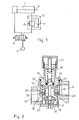
- this shows an example of application of a compressed-air economizing device 5 for controlling a pneumatic cylinder 1, the working stroke of which must be carried out with a first value of thrust power, by feeding for example compressed air at a pressure of approximately 5 or 6 Atm., whereas the return stroke can be carried out with a much lower value of power, for example with compressed air at a pressure of approximately 2 Atm., sufficient to overcome the friction in the system.
- the chamber of the cylinder 1, on the opposite side to that of the rod 2, is connected directly to a source 3 of compressed air, through a distributor 4, whereas on the rod side it is connected to the aforementioned source, by means of an economizing device 5 in order to avoid a pointless waste of compressed air, at high pressure, just for the return stroke of the cylinder 1.
- the pressure economizing device 5, in the diagram of figure 1, is schematically represented with the pressure reducer 6 inserted into a main passage for feeding the fluid under pressure to the cylinder 1, parallel to which is a single-acting valve 7 for allowing the fluid to flow from the cylinder 1 towards an outlet, that is to say, in the opposite direction to that mentioned previously, during the working stroke of the cylinder.
- FIG. 2 of the accompanying drawing shows a first embodiment of compressed-air economizing device, according to this invention.
- Such device comprises a body 8 conventionally defining an inlet 9 and an outlet 10 for the fluid. Between the inlet 9 and the outlet 10 the body is provided with a cavity 11 defining a pressure reducing chamber, into which is inserted, for example, screwed in, the body 12 of an automatic pressure reducing valve, described hereunder.
- the pressure reducing valve 12 comprises a sleeve or cylindrical baffle 13 which extends axially into the chamber starting from the body 12 of the valve; the sleeve 13 thus defines an internal rectilinear section 14, of the main passage for the fluid, between the inlet 9 and the outlet 10.
- a small piston 15 biased by a spring 16 the tension of which can be adjusted by acting upon a knob 17 in order to set the degree of reduction in the pressure.
- the piston 15 extends towards the chamber 11 by means of a stem 18 onto which is screwed or fixed a shutter 19 which is movable towards a valve seat 20 situated on the inner end of the baffle or sleeve 13, as shown.
- the section 14 of the main passage of the fluid, defined within the sleeve 13, communicates directly, on one side, with the pressure reducing chamber 11, which, in turn, opens out towards the outlet 10, whereas on the other side it communicates, by means of secondary passages, for example, by means of radial apertures 21 formed in the wall of the sleeve 13 situated above a single-acting valve, described further on, with an annular chamber 22 which coaxially encircles the sleeve 13 and which opens out towards the inlet 9.
- annular chamber 22 is in direct communication with the inlet 9, however said annular chamber is also in communication with the fluid outlet 10, for example, through the pressure reducing chamber 11 itself, thus defining a branched out passage comprising a single-acting valve operating in the previously described manner.
- a single-acting valve comprises an annular seat formed by a first circular ledge 23, on the outermost edge of the cylindrical sleeve 13, and by a second circular ledge 24 within the body 8 of the device; the two ledges 23 and 24 are radially separated from each other so as to create an annular passage for the fluid.
- the single-acting valve is completed, in the example shown in figure 2, by an annular shutter 25, movable within the annular chamber 22; the shutter is made to close, against the seats 23 and 24, by a spring 26 and by the pressure of the fluid itself which is exerted within the chamber 22, during the passage from the inlet 9 to the outlet 10 of the fluid for controlling the working stroke of the cylinder 1.
- the shutter 19 of the pressure reducing valve 12 is forced to close, against the seat 20, by the pressure of the fluid itself, whilst the single-acting valve 23, 24 and 25, overcoming the counter force of the spring 26, is made to open.
- the concentric arrangement of the pressure-reducing valve and of the single-acting valve makes it possible to achieve a device with a compact and highly functional structure, insofar as the dimensions of the various parts and the sectional areas of flow of the fluid can be sized according to the desired capacity, keeping the overall dimensions of the entire device to a minimum.
- the device may be made from any suitable material, at a very low cost, due to the fact, for example, that the body 8 of the device can now be moulded without calling for special machining.
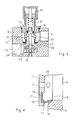
- the example in figures 3 and 4 shows an alternative embodiment of the device, aimed at a different embodiment of the single-acting valve; consequently the parts which remain unchanged, with respect to the previous case, bear the same numerical references.
- the device of figure 3 also comprises a body 8 with an inlet 9 and an outlet 10 for the fluid in the indicated direction and a pressure reducing chamber 11 within which the reducing valve 19, 20 is situated.
- Reference 13 indicates the cylindrical sleeve, defining the section 14 of the main passage of the fluid and the annular chamber 22, coaxial to the sleeve itself.
- the reference numbers 23 and 24 still indicate the annular ledges on the sleeve 13 and on the body 8 of the device, defining the annular seat of the single-acting valve; unlike the previous example, here the shutter of the single-acting valve is made in such a way as to eliminate the need for any biasing spring whatsoever, due to the fact that any such spring could wear out as a result of its repeated and continuous operation, and due to the fact of being in direct contact with compressed air or a fluid which generally contains corrosive substances which tend to deteriorate the spring itself.
- the elimination of such spring and its replacement with elastic characteristics of the element itself designed to form a seal makes it possible to substantially improve the device, whilst still maintaining the innovatory features of the previous example.
- the shutter of the single-acting valve consists of a flexible washer, comprising a circular band 27 which fits tightly into a groove 29 formed on the outside of the cylindrical sleeve 23, from which protrudes, radially, an annular flange 28 connected to the circular band 27, by means of a portion 30 defining a flexible hinge.
- the flange 28 fits tightly onto the aforementioned annular seats 23 and 24. Therefore, when the upper face of the flange 28, that is to say, that facing the annular chamber 13, is subjected to a greater pressure than that exerted upon the other face, the washer is pushed tightly against the seat 24, thereby closing the single-acting valve.
Landscapes
- Engineering & Computer Science (AREA)
- Physics & Mathematics (AREA)
- Fluid Mechanics (AREA)
- Mechanical Engineering (AREA)
- General Engineering & Computer Science (AREA)
- Lift Valve (AREA)
Applications Claiming Priority (2)
| Application Number | Priority Date | Filing Date | Title |
|---|---|---|---|
| IT21438/81A IT1139088B (it) | 1981-04-29 | 1981-04-29 | Dispositivo economizzatore di aria compressa,comprendente una valvola unidirezionale coassiale ad una valvola riduttrice di pressione |
| IT2143881 | 1981-04-29 |
Publications (3)
| Publication Number | Publication Date |
|---|---|
| EP0067934A2 true EP0067934A2 (de) | 1982-12-29 |
| EP0067934A3 EP0067934A3 (en) | 1983-01-12 |
| EP0067934B1 EP0067934B1 (de) | 1985-01-16 |
Family
ID=11181788
Family Applications (1)
| Application Number | Title | Priority Date | Filing Date |
|---|---|---|---|
| EP82103026A Expired EP0067934B1 (de) | 1981-04-29 | 1982-04-08 | Druckluftspareinrichtung |
Country Status (3)
| Country | Link |
|---|---|
| EP (1) | EP0067934B1 (de) |
| DE (1) | DE3261914D1 (de) |
| IT (1) | IT1139088B (de) |
Cited By (4)
| Publication number | Priority date | Publication date | Assignee | Title |
|---|---|---|---|---|
| GB2137320A (en) * | 1983-03-31 | 1984-10-03 | Graubremse Gmbh | Pressure-limiting valve |
| AT386258B (de) * | 1985-03-15 | 1988-07-25 | Hoerbiger Ventilwerke Ag | Steuerungsanordnung fuer pneumatische arbeitszylinder |
| GB2251477A (en) * | 1990-12-15 | 1992-07-08 | Gisag Ag | A core shooting unit and valve therefor |
| WO2016202356A1 (de) * | 2015-06-15 | 2016-12-22 | Festo Ag & Co. Kg | Antriebssystem und verfahren zum betreiben eines fluidbetätigen drehantriebs |
Families Citing this family (1)
| Publication number | Priority date | Publication date | Assignee | Title |
|---|---|---|---|---|
| CN102635587A (zh) * | 2012-04-28 | 2012-08-15 | 汕头市甜甜乐糖果食品有限公司 | 气缸供气控制结构 |
Family Cites Families (6)
| Publication number | Priority date | Publication date | Assignee | Title |
|---|---|---|---|---|
| DE1650440B2 (de) * | 1967-09-26 | 1973-11-22 | Knorr-Bremse Gmbh, 8000 Muenchen | Drosselruckschlagventil |
| US3643684A (en) * | 1970-03-16 | 1972-02-22 | William L Moore | Pressure control devices for pneumatic circuits |
| FR2343280A1 (fr) * | 1976-03-05 | 1977-09-30 | Bouteille Daniel | Limiteur de debit unidirectionnel |
| US4175473A (en) * | 1976-06-08 | 1979-11-27 | Shoketsu Kinzoku Kogyo Kabushiki Kaisha | Fluid circuit |
| FR2482212A1 (fr) * | 1980-04-23 | 1981-11-13 | Bouteille Daniel | Dispositif economiseur de gaz comprime |
| FR2481403A1 (fr) * | 1980-04-23 | 1981-10-30 | Bouteille Daniel | Dispositif economiseur d'air comprime |
-
1981
- 1981-04-29 IT IT21438/81A patent/IT1139088B/it active
-
1982
- 1982-04-08 DE DE8282103026T patent/DE3261914D1/de not_active Expired
- 1982-04-08 EP EP82103026A patent/EP0067934B1/de not_active Expired
Cited By (5)
| Publication number | Priority date | Publication date | Assignee | Title |
|---|---|---|---|---|
| GB2137320A (en) * | 1983-03-31 | 1984-10-03 | Graubremse Gmbh | Pressure-limiting valve |
| AT386258B (de) * | 1985-03-15 | 1988-07-25 | Hoerbiger Ventilwerke Ag | Steuerungsanordnung fuer pneumatische arbeitszylinder |
| GB2251477A (en) * | 1990-12-15 | 1992-07-08 | Gisag Ag | A core shooting unit and valve therefor |
| ES2082672A1 (es) * | 1990-12-15 | 1996-03-16 | Gisag Ag Giesserei Masch | Disposicion de valvula de admision de aire a presion y de escape para maquinas de moldeo, especialmente para maquinas expulsoras de machos. |
| WO2016202356A1 (de) * | 2015-06-15 | 2016-12-22 | Festo Ag & Co. Kg | Antriebssystem und verfahren zum betreiben eines fluidbetätigen drehantriebs |
Also Published As
| Publication number | Publication date |
|---|---|
| DE3261914D1 (en) | 1985-02-28 |
| EP0067934A3 (en) | 1983-01-12 |
| IT1139088B (it) | 1986-09-17 |
| EP0067934B1 (de) | 1985-01-16 |
| IT8121438A0 (it) | 1981-04-29 |
Similar Documents
| Publication | Publication Date | Title |
|---|---|---|
| US4026322A (en) | Reciprocating pump check valve assembly | |
| EP0795707A1 (de) | Hubventil | |
| US7225830B1 (en) | Fluid control valve | |
| US4494572A (en) | Four-way poppet valve assembly | |
| US3886848A (en) | Pressure operated directional control valve | |
| JP3130932B2 (ja) | パトローネ式弁 | |
| US4595170A (en) | Solenoid valve | |
| US5125575A (en) | Valve | |
| EP0520212A1 (de) | Geschwindigkeitssteuerung | |
| ES416870A1 (es) | Perfeccionamientos introducidos en valvulas de retencion deseguridad. | |
| US4026327A (en) | Rapid opening valve for steam-operated power devices | |
| GB2327740A (en) | Valve seal mechanism | |
| US4458718A (en) | Spool valve and seal having zero leakage | |
| EP0067934B1 (de) | Druckluftspareinrichtung | |
| US4020863A (en) | Fluid pressure regulator construction | |
| US3283784A (en) | Control valve for hydraulic machinery | |
| US5255604A (en) | Pressure fluid supply valve assembly | |
| US5630401A (en) | Combined fuel injection pump and nozzle | |
| US4905730A (en) | Override check valve | |
| US6382243B2 (en) | Pressure-reducing valve | |
| US8011639B2 (en) | Poppet type flow control valve | |
| KR950033122A (ko) | 유체압 피스톤 발동기 | |
| US4407640A (en) | Reciprocating pump having unique pressure control valve construction | |
| EP0097246A2 (de) | Ventilvorrichtung zum langsam unter Druck bringen von pneumatischen Systemen | |
| US3316926A (en) | Pressure responsive supply-exhaust valve |
Legal Events
| Date | Code | Title | Description |
|---|---|---|---|
| PUAI | Public reference made under article 153(3) epc to a published international application that has entered the european phase |
Free format text: ORIGINAL CODE: 0009012 |
|
| PUAL | Search report despatched |
Free format text: ORIGINAL CODE: 0009013 |
|
| AK | Designated contracting states |
Designated state(s): CH DE FR GB LI NL SE |
|
| AK | Designated contracting states |
Designated state(s): CH DE FR GB LI NL SE |
|
| 17P | Request for examination filed |
Effective date: 19830303 |
|
| GRAA | (expected) grant |
Free format text: ORIGINAL CODE: 0009210 |
|
| AK | Designated contracting states |
Designated state(s): CH DE FR GB LI NL SE |
|
| REF | Corresponds to: |
Ref document number: 3261914 Country of ref document: DE Date of ref document: 19850228 |
|
| ET | Fr: translation filed | ||
| PLBE | No opposition filed within time limit |
Free format text: ORIGINAL CODE: 0009261 |
|
| STAA | Information on the status of an ep patent application or granted ep patent |
Free format text: STATUS: NO OPPOSITION FILED WITHIN TIME LIMIT |
|
| 26N | No opposition filed | ||
| PGFP | Annual fee paid to national office [announced via postgrant information from national office to epo] |
Ref country code: NL Payment date: 19860430 Year of fee payment: 5 |
|
| PG25 | Lapsed in a contracting state [announced via postgrant information from national office to epo] |
Ref country code: SE Effective date: 19870409 |
|
| PG25 | Lapsed in a contracting state [announced via postgrant information from national office to epo] |
Ref country code: LI Effective date: 19870430 Ref country code: CH Effective date: 19870430 |
|
| PG25 | Lapsed in a contracting state [announced via postgrant information from national office to epo] |
Ref country code: NL Effective date: 19871101 |
|
| NLV4 | Nl: lapsed or anulled due to non-payment of the annual fee | ||
| PG25 | Lapsed in a contracting state [announced via postgrant information from national office to epo] |
Ref country code: FR Free format text: LAPSE BECAUSE OF NON-PAYMENT OF DUE FEES Effective date: 19871230 |
|
| GBPC | Gb: european patent ceased through non-payment of renewal fee | ||
| REG | Reference to a national code |
Ref country code: CH Ref legal event code: PL |
|
| PG25 | Lapsed in a contracting state [announced via postgrant information from national office to epo] |
Ref country code: DE Effective date: 19880101 |
|
| REG | Reference to a national code |
Ref country code: FR Ref legal event code: ST |
|
| PG25 | Lapsed in a contracting state [announced via postgrant information from national office to epo] |
Ref country code: GB Effective date: 19881121 |
|
| EUG | Se: european patent has lapsed |
Ref document number: 82103026.9 Effective date: 19880906 |