EP0067946A2 - Structure d'antenne réseau à poids faible - Google Patents
Structure d'antenne réseau à poids faible Download PDFInfo
- Publication number
- EP0067946A2 EP0067946A2 EP82103855A EP82103855A EP0067946A2 EP 0067946 A2 EP0067946 A2 EP 0067946A2 EP 82103855 A EP82103855 A EP 82103855A EP 82103855 A EP82103855 A EP 82103855A EP 0067946 A2 EP0067946 A2 EP 0067946A2
- Authority
- EP
- European Patent Office
- Prior art keywords
- waveguides
- antenna
- dielectric
- sheets
- array
- Prior art date
- Legal status (The legal status is an assumption and is not a legal conclusion. Google has not performed a legal analysis and makes no representation as to the accuracy of the status listed.)
- Granted
Links
Images

Classifications
-
- H—ELECTRICITY
- H01—ELECTRIC ELEMENTS
- H01Q—ANTENNAS, i.e. RADIO AERIALS
- H01Q1/00—Details of, or arrangements associated with, antennas
- H01Q1/42—Housings not intimately mechanically associated with radiating elements, e.g. radome
- H01Q1/422—Housings not intimately mechanically associated with radiating elements, e.g. radome comprising two or more layers of dielectric material
Definitions
- This invention relates to the field of slot array antennas and more particularly to lightweight armored antennas having high structural strength for use in battlefield environments.
- the slot array antennas have been used for radar applications for many years.
- the slot array antennas generally comprise multiple parallel rows of waveguides having slots in the waveguide walls that face the direction of radiation, structural supports for the waveguides, a radome to weatherize the antenna, and a pedestal to support and rotate the antenna assembly.
- the antenna assembly generally has a small depth, but a relatively large surface area.
- antennas of this type on seagoing vessels presents unique problems.
- the antenna usually must be situated high on a mast where it is highly exposed to enemy fire and explosive detonations (nuclear and conventional) from all aspect angles.
- Weight is a highly critical factor, especially since weight above the waterline must be ballasted with greater weights below the waterline to maintain ship stability. Every pound of the antenna must usually be ballasted with about ten pounds below deck. Armoring the antenna and strengthening the structure of the broad, thin antenna panel to allow it to survive flak and the blast effects of explosives adds much weight which will slow the ship.
- Present antenna designs generally utilize a riveted monocoque structure supporting the array of slotted waveguides and their sinuous feed with ribs, intercostals, a polyester fiberglass radome, and various supplementary pieces.
- a backbone casting is located behind the monocoque antenna structure, providing the structural interface between the antenna and the pedestal. Conditioning the antenna against the thermal pulse of a nuclear explosion requires the addition of heat resistant dielectric material.
- a further purpose of this invention is to provide a method for making a lightweight slot array antenna.
- the present invention provides a lightweight radome for enclosing and structurally supporting an array of slotted waveguides.
- the radome consists of two or more sheets of an appropriate dielectric material with a honeycombed dielectric material disposed between and bonded to each pair of adjacent dielectric sheets.
- the array of slotted waveguides is disposed inside the radome.
- Honeycombed dielectric material may be disposed between and bonded to each'pair of adjacent waveguides.
- the axes of the cells of the honeycombed material disposed between the waveguides should be in the plane of the waveguide array and perpendicular to the axes of the waveguides.
- the axes of the cells of the honeycombed material disposed between the dielectric sheets of the radome should be perpendicular to the planes of the dielectric sheets.
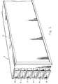
- FIG. 1 A segment of a six-waveguide array module 10 is shown in FIG. 1.
- a support structure 12 encases six waveguides 15, 16, 17, 18, 19, and 20. These aluminum waveguides can be chemically milled to 0.03 inch wall thickness. Each waveguide extends entirely through the support structure 12 and has a suitable flange at one end for connection to the feed network (not shown).
- the construction of the support structure is shown in FIGs. 2 and 3.
- a ground plane 25 lies adjacent to the rear narrow walls of the waveguides 15 and 16.
- the ground plane 25 can be a fine monel screen.
- a honeycomb core material 30 is bonded to the broad walls of the waveguides to prevent the thin waveguide walls from buckling under compressive forces.
- Each radome 35 and 40 may comprise three parallel sheets 45 of dielectric material with a layer of honeycomb core 50 bonded between each pair of dielectric sheets 45.
- the thickness of the front radome 35 should be about one-half of the wavelength of the radiant energy transmitted from the slot array.
- the dielectric sheets 45 in each radome 35 and 40 may be made of fiberglass.
- the outer dielectric sheet 45 of each radome 35 and 40 can be a polyimide-fiberglass to better enable the radomes to withstand the thermal pulses of a nuclear explosion.
- the other dielectric sheets can be made of epoxy-fiberglass, which is less expensive.
- the fiberglass can also utilize unidirectional glass, which is glass that has more fibers oriented parallel to the axes of the waveguides than oriented perpendicular thereto. A 65%/35% blend (65% of the fibers oriented parallel to the waveguides axes) has been found-to be optimum.
- the use of unidirectional glass for the dielectric sheets 45 increases the modulus of elasticity in the desired direction to better enable the antenna to withstand explosive blasts.
- the honeycomb cores 30 and 50 may be made of glass-reinforced phenolic, which can be purchased from Hexcel, Inc. of Dublin, California.
- the honeycomb core 50 of the radomes 35 and 40 it is desirable that the ribbon direction of the core be parallel to the axes of the waveguides. This means that some of the bonds between individual cells of the honeycomb will be oriented parallel to the waveguide axes, but none will be perpendicular thereto. This orientation of the honeycomb will give the radomes 35 and 40 greater strength.
- the honeycomb core 30 disposed between the waveguides it is desirable for the honeycomb core 30 disposed between the waveguides to be oriented so that the axes of the honeycomb cells are in the plane of the array of waveguides'and perpendicular to the axes of the waveguides. It is also desirable that the honeycomb core 50 disposed between the dielectric sheets 45 should be oriented so that the axes of the honeycomb cells are perpendicular to the plane of the dielectric sheets 45.
- the antenna module 10 may be constructed by arranging the various waveguides in the desired array and inserting a honeycomb core 30 between each pair of waveguides. Strips of dry film structural adhesive should be located between the honeycomb core and the waveguide walls as required and then activated by heat.
- the front and rear radomes 35 and 40 are laid up a layer at a time, with dry film structural adhesive located between the dielectric sheets 45 and the honeycomb core 50 as required and then activated by heat. Finally, each radome 35 and 40 is positioned against the array of waveguides, with an adhesive film located as required to form a tight seal.
- an antenna module can be constructed to employ as many waveguides as desired.
- the radome sandwich structure may have one or as many layers of honeycombed core sandwiched between dielectric sheets as is desirable for a particular application. It may also be desirable to pre-impregnate the sheets with dry adhesive, so that the components may simply be positioned and heated during manufacture. Numerous and varied other arrangements can be easily devised in accordance with the principles of this invention by those skilled in the art without departing from the spirit and scope of the invention.
Landscapes
- Details Of Aerials (AREA)
- Waveguide Aerials (AREA)
Applications Claiming Priority (2)
| Application Number | Priority Date | Filing Date | Title |
|---|---|---|---|
| US06/275,555 US4517571A (en) | 1981-06-19 | 1981-06-19 | Lightweight slot array antenna structure |
| US275555 | 1981-06-19 |
Publications (3)
| Publication Number | Publication Date |
|---|---|
| EP0067946A2 true EP0067946A2 (fr) | 1982-12-29 |
| EP0067946A3 EP0067946A3 (en) | 1983-01-05 |
| EP0067946B1 EP0067946B1 (fr) | 1986-07-23 |
Family
ID=23052804
Family Applications (1)
| Application Number | Title | Priority Date | Filing Date |
|---|---|---|---|
| EP82103855A Expired EP0067946B1 (fr) | 1981-06-19 | 1982-05-05 | Structure d'antenne réseau à poids faible |
Country Status (8)
| Country | Link |
|---|---|
| US (1) | US4517571A (fr) |
| EP (1) | EP0067946B1 (fr) |
| DE (1) | DE3272119D1 (fr) |
| ES (1) | ES512641A0 (fr) |
| GR (1) | GR79488B (fr) |
| NO (1) | NO155559C (fr) |
| PT (1) | PT75014B (fr) |
| TR (1) | TR21839A (fr) |
Cited By (1)
| Publication number | Priority date | Publication date | Assignee | Title |
|---|---|---|---|---|
| GB2302211A (en) * | 1987-04-14 | 1997-01-08 | Thomson Csf | Wall for radomes,and radomes thus obtained |
Families Citing this family (10)
| Publication number | Priority date | Publication date | Assignee | Title |
|---|---|---|---|---|
| CA1233246A (fr) * | 1985-01-18 | 1988-02-23 | Peter J. Wood | Radar aeroporte a balayage lateral |
| US4700195A (en) * | 1985-10-01 | 1987-10-13 | Harris Corporation | Waveguide fed composite horn antenna |
| US5103241A (en) * | 1989-07-28 | 1992-04-07 | Hughes Aircraft Company | High Q bandpass structure for the selective transmission and reflection of high frequency radio signals |
| US5579020A (en) * | 1993-09-27 | 1996-11-26 | Sensis Corporation | Lightweight edge-slotted waveguide antenna structure |
| US6888115B2 (en) * | 2000-05-19 | 2005-05-03 | Industrial Microwave Systems, L.L.C. | Cascaded planar exposure chamber |
| US20040183744A1 (en) * | 2003-03-18 | 2004-09-23 | Raiman Clifford E. | Antenna for explosive environments |
| US8149177B1 (en) * | 2008-05-09 | 2012-04-03 | The United States Of America As Represented By The Secretary Of The Air Force | Slotted waveguide antenna stiffened structure |
| US9236652B2 (en) * | 2012-08-21 | 2016-01-12 | Raytheon Company | Broadband array antenna enhancement with spatially engineered dielectrics |
| US11201414B2 (en) | 2018-12-18 | 2021-12-14 | Veoneer Us, Inc. | Waveguide sensor assemblies and related methods |
| US11914067B2 (en) | 2021-04-29 | 2024-02-27 | Veoneer Us, Llc | Platformed post arrays for waveguides and related sensor assemblies |
Family Cites Families (6)
| Publication number | Priority date | Publication date | Assignee | Title |
|---|---|---|---|---|
| US2956281A (en) * | 1954-09-08 | 1960-10-11 | Edward B Mcmillan | Dielectric walls for transmission of electromagnetic radiation |
| GB1025403A (en) * | 1962-06-16 | 1966-04-06 | Felten & Guilleaume Carlswerk | Rectangular waveguide and method of manufacturing it |
| US3518688A (en) * | 1965-11-22 | 1970-06-30 | Itt | Microwave strip transmission line adapted for integral slot antenna |
| US3453620A (en) * | 1968-01-29 | 1969-07-01 | North American Rockwell | Radome structural composite |
| US4255752A (en) * | 1978-09-13 | 1981-03-10 | International Telephone And Telegraph Corporation | Lightweight composite slotted-waveguide antenna and method of manufacture |
| US4229745A (en) * | 1979-04-30 | 1980-10-21 | International Telephone And Telegraph Corporation | Edge slotted waveguide antenna array with selectable radiation direction |
-
1981
- 1981-06-19 US US06/275,555 patent/US4517571A/en not_active Expired - Fee Related
-
1982
- 1982-05-05 GR GR68076A patent/GR79488B/el unknown
- 1982-05-05 EP EP82103855A patent/EP0067946B1/fr not_active Expired
- 1982-05-05 DE DE8282103855T patent/DE3272119D1/de not_active Expired
- 1982-05-28 ES ES512641A patent/ES512641A0/es active Granted
- 1982-05-28 NO NO821808A patent/NO155559C/no not_active IP Right Cessation
- 1982-06-02 TR TR21839A patent/TR21839A/xx unknown
- 1982-06-04 PT PT75014A patent/PT75014B/pt unknown
Cited By (3)
| Publication number | Priority date | Publication date | Assignee | Title |
|---|---|---|---|---|
| GB2302211A (en) * | 1987-04-14 | 1997-01-08 | Thomson Csf | Wall for radomes,and radomes thus obtained |
| US5631663A (en) * | 1987-04-14 | 1997-05-20 | Thomson-Csf | Wall for radomes, and radomes thus obtained |
| GB2302211B (en) * | 1987-04-14 | 1997-08-13 | Thomson Csf | Wall for radomes,and radomes thus obtained |
Also Published As
| Publication number | Publication date |
|---|---|
| NO155559B (no) | 1987-01-05 |
| NO155559C (no) | 1987-04-15 |
| DE3272119D1 (en) | 1986-08-28 |
| US4517571A (en) | 1985-05-14 |
| NO821808L (no) | 1982-12-20 |
| ES8308159A1 (es) | 1983-07-01 |
| PT75014B (en) | 1983-12-23 |
| GR79488B (fr) | 1984-10-30 |
| PT75014A (en) | 1982-07-01 |
| EP0067946A3 (en) | 1983-01-05 |
| EP0067946B1 (fr) | 1986-07-23 |
| ES512641A0 (es) | 1983-07-01 |
| TR21839A (tr) | 1985-09-06 |
Similar Documents
| Publication | Publication Date | Title |
|---|---|---|
| US5771027A (en) | Composite antenna | |
| US5182155A (en) | Radome structure providing high ballistic protection with low signal loss | |
| US4517571A (en) | Lightweight slot array antenna structure | |
| US5666128A (en) | Modular supertile array antenna | |
| US5184141A (en) | Structurally-embedded electronics assembly | |
| US4625214A (en) | Dual gridded reflector structure | |
| CN106848558B (zh) | 航天器太阳能帆板共形天线 | |
| US4635071A (en) | Electromagnetic radiation reflector structure | |
| US8704724B2 (en) | Method and arrangement for a low radar cross section antenna | |
| JP4421056B2 (ja) | スペースクラフトの外部放射要素により飛行中に吸収される外部熱線束のシミュレーション方法と、この方法を実施するためのスペースクラフト | |
| US5486399A (en) | Self-supporting convex cover for spacecraft | |
| WO2013130028A2 (fr) | Ouverture eo/rf hybride conforme | |
| US3096519A (en) | Composite reflector for two independent orthogonally polarized beams | |
| US2641561A (en) | Sandwich-type radome panel | |
| You et al. | Microstrip antenna for SAR application with composite sandwich construction: surface-antenna-structure demonstration | |
| US5731777A (en) | Radio-frequency absorbing fin blanket | |
| GB2125633A (en) | Antenna construction | |
| US11726169B1 (en) | System for augmenting 360-degree aspect monostatic radar cross section of an aircraft | |
| US3886558A (en) | Artificial dielectric material for controlling antennae patterns | |
| US8766875B2 (en) | Lightweight stiffener with integrated RF cavity-backed radiator for flexible RF emitters | |
| EP0742095A2 (fr) | Structure de matériau composite apte à absorber et dissiper l'énergie de rayonnement électromagnétique incident, notamment pour véhicules routiers, aéronefs et navires et pour installations fixées à la terre | |
| KR102717978B1 (ko) | 전자기파 흡수 기능을 갖는 복합재 패널 모듈 및 이를 포함하는 샌드위치 구조체 | |
| CN117039454A (zh) | 一种带有加载集总电阻吸波格栅、方法及进气道 | |
| KR102558314B1 (ko) | 전자기파 흡수 기능을 갖는 복합재 패널 및 이를 포함하는 구조체 | |
| WO1988004480A1 (fr) | Reflecteur d'antenne composite pourvu d'un reflecteur secondaire polarise |
Legal Events
| Date | Code | Title | Description |
|---|---|---|---|
| PUAI | Public reference made under article 153(3) epc to a published international application that has entered the european phase |
Free format text: ORIGINAL CODE: 0009012 |
|
| PUAL | Search report despatched |
Free format text: ORIGINAL CODE: 0009013 |
|
| AK | Designated contracting states |
Designated state(s): DE GB IT |
|
| AK | Designated contracting states |
Designated state(s): DE GB IT |
|
| 17P | Request for examination filed |
Effective date: 19830624 |
|
| RAP1 | Party data changed (applicant data changed or rights of an application transferred) |
Owner name: HUGHES AIRCRAFT COMPANY |
|
| ITF | It: translation for a ep patent filed | ||
| GRAA | (expected) grant |
Free format text: ORIGINAL CODE: 0009210 |
|
| AK | Designated contracting states |
Kind code of ref document: B1 Designated state(s): DE GB IT |
|
| REF | Corresponds to: |
Ref document number: 3272119 Country of ref document: DE Date of ref document: 19860828 |
|
| PLBE | No opposition filed within time limit |
Free format text: ORIGINAL CODE: 0009261 |
|
| STAA | Information on the status of an ep patent application or granted ep patent |
Free format text: STATUS: NO OPPOSITION FILED WITHIN TIME LIMIT |
|
| 26N | No opposition filed | ||
| ITTA | It: last paid annual fee | ||
| REG | Reference to a national code |
Ref country code: GB Ref legal event code: 732E |
|
| PGFP | Annual fee paid to national office [announced via postgrant information from national office to epo] |
Ref country code: GB Payment date: 20000419 Year of fee payment: 19 |
|
| PGFP | Annual fee paid to national office [announced via postgrant information from national office to epo] |
Ref country code: DE Payment date: 20000425 Year of fee payment: 19 |
|
| PG25 | Lapsed in a contracting state [announced via postgrant information from national office to epo] |
Ref country code: GB Free format text: LAPSE BECAUSE OF NON-PAYMENT OF DUE FEES Effective date: 20010505 |
|
| GBPC | Gb: european patent ceased through non-payment of renewal fee |
Effective date: 20010505 |
|
| PG25 | Lapsed in a contracting state [announced via postgrant information from national office to epo] |
Ref country code: DE Free format text: LAPSE BECAUSE OF NON-PAYMENT OF DUE FEES Effective date: 20020301 |