EP0067948B1 - Methode und Apparat zum Produzieren von Flüssigkeitstropfen auf Befehl - Google Patents
Methode und Apparat zum Produzieren von Flüssigkeitstropfen auf Befehl Download PDFInfo
- Publication number
- EP0067948B1 EP0067948B1 EP19820103883 EP82103883A EP0067948B1 EP 0067948 B1 EP0067948 B1 EP 0067948B1 EP 19820103883 EP19820103883 EP 19820103883 EP 82103883 A EP82103883 A EP 82103883A EP 0067948 B1 EP0067948 B1 EP 0067948B1
- Authority
- EP
- European Patent Office
- Prior art keywords
- drop
- nozzle
- nozzle passage
- ink
- demand
- Prior art date
- Legal status (The legal status is an assumption and is not a legal conclusion. Google has not performed a legal analysis and makes no representation as to the accuracy of the status listed.)
- Expired
Links
Images

Classifications
-
- B—PERFORMING OPERATIONS; TRANSPORTING
- B41—PRINTING; LINING MACHINES; TYPEWRITERS; STAMPS
- B41J—TYPEWRITERS; SELECTIVE PRINTING MECHANISMS, i.e. MECHANISMS PRINTING OTHERWISE THAN FROM A FORME; CORRECTION OF TYPOGRAPHICAL ERRORS
- B41J2/00—Typewriters or selective printing mechanisms characterised by the printing or marking process for which they are designed
- B41J2/005—Typewriters or selective printing mechanisms characterised by the printing or marking process for which they are designed characterised by bringing liquid or particles selectively into contact with a printing material
- B41J2/01—Ink jet
- B41J2/135—Nozzles
- B41J2/145—Arrangement thereof
- B41J2/155—Arrangement thereof for line printing
-
- B—PERFORMING OPERATIONS; TRANSPORTING
- B41—PRINTING; LINING MACHINES; TYPEWRITERS; STAMPS
- B41J—TYPEWRITERS; SELECTIVE PRINTING MECHANISMS, i.e. MECHANISMS PRINTING OTHERWISE THAN FROM A FORME; CORRECTION OF TYPOGRAPHICAL ERRORS
- B41J2/00—Typewriters or selective printing mechanisms characterised by the printing or marking process for which they are designed
- B41J2/005—Typewriters or selective printing mechanisms characterised by the printing or marking process for which they are designed characterised by bringing liquid or particles selectively into contact with a printing material
- B41J2/01—Ink jet
- B41J2/135—Nozzles
- B41J2/14—Structure thereof only for on-demand ink jet heads
- B41J2/14201—Structure of print heads with piezoelectric elements
- B41J2/14298—Structure of print heads with piezoelectric elements of disc type
Definitions
- This invention relates to methods and apparatus for generating liquid drops on demand under control of a suitable electrical signal.
- Ink jet printing has been known in the prior art, including systems which use a pressure generated continuous stream of ink, which is broken into individual drops by a continuously energized transducer. The individual drops are selectively charged and deflected either to the print medium for printing or to a sump where the drops are collected and recirculated. Examples of these pressurized systems include US-A-3,596,275 to Sweet, and 3,373,437 to Sweet et al. There have also been known in the prior art inkjet printing systems in which a transducer is used to generate ink drops on demand. One example of such a system is commonly assigned US-A-3,787,884 to Demer.
- the ink is supplied to a cavity by gravity flow and a transducer mounted in the back of the cavity produces motion when energized by an appropriate voltage pulse, which results in the generation of an ink drop so that only those ink drops required for printing are generated.
- a transducer mounted in the back of the cavity produces motion when energized by an appropriate voltage pulse, which results in the generation of an ink drop so that only those ink drops required for printing are generated.
- the prior art drop-on-demand printing systems have been limited by low drop production rates, low resolution, and low efficiency.
- Typical prior art drop-on-demand printing systems have utilized a constant cross-section nozzle and ink having a viscosity during operation lower than 10 centipoise. Attempts to increase the drop production rates, and thus to increase the print resolution, have led to stream instability.
- the invention provides a drop-on-demand ink jet printing method and apparatus comprising a print head having a fluid chamber supplied with a suitable high viscosity marking fluid.
- An orifice comprising a strongly converging nozzle is in fluid communication with the fluid chamber, and an electromechanical transducer is mounted in mechanical communication with the fluid chamber. The transducer is selectively energized with a series of signals so that one drop of the marking fluid is ejected from the orifice for each of the signals having at least a predetermined amplitude.
- the invention provides a method of producing single liquid drops of demand, comprising ejecting the volume of liquid required to form a single drop from a tapering nozzle passage as and when a drop is demanded, said method being characterised in that the liquid used has a viscosity in the range of 15 to 100 centipoise and in that the nozzle passage tapers towards the exit orifice of the nozzle and has an included or apex angle of between 60 and 80 degrees.
- the invention includes apparatus for carrying out the foregoing method, said apparatus comprising a print head having an ink chamber to which ink is supplied and from which ink exits through a nozzle passage under the control of an electromechanical transducer mounted in mechanical communication with the ink chamber, said transducer being operative on appropriate energisation to cause a single drop to be ejected from the nozzle and said nozzle passage converging towards the exit orifice of the nozzle, said apparatus being characterised in that the nozzle passage has an included or apex angle of between 60 and 80 degrees whereby single drops of liquid having a viscosity in the range 15 to 100 centipoise can be formed.
- the printer apparatus comprises a print head 10 to which is supplied high viscosity liquid ink from ink supply means 12.
- the viscosity requirement is a function of nozzle size and maximum drop-on-demand drop production rate.
- the viscosity for inks for high resolution printing extends up to 100 centipoise, and the viscosity can be substantially higher for applications in which lower resolution is suitable.
- Control means 14 provides the voltage control pulses to selectively energize print head 10 to produce one ink drop for each voltage pulse supplied to print head 10.
- Print head 10 comprises head body 20 having a chamber or cavity 22 formed therein. Cavity 22 is maintained filled with ink through supply line 24 from ink supply means 12.
- Ink from supply means 12 is not pressurized so the ink in cavity 22 is maintained at or near atmospheric pressure under static conditions.
- An exit from cavity 22 is provided by nozzle portion 26 which is designed so that the ink does not flow out of nozzle portion 26 under static conditions.
- An intermediate ink reservoir 28 is formed in head body 20 and is separated from cavity 22 by internal wall portion 30.
- the top of cavity 22, as shown in Figure 2, is closed by a suitable transducer means which is fixed to the head body.
- Internal wall portion 30 is designed so that a narrow passageway 32 is provided for the transfer of liquid ink from intermediate ink reservoir 28 to ink cavity 22.
- the transducer means comprises a membrane member 34 which is fastened to an electromechanical transducer 36.
- Transducer 36 displaces radially when energized with a suitable voltage pulse and bends membrane 34 inwardly (as shown dotted in Figure 3), and produces a pressure wave in cavity 22 so that liquid ink is expelled out through nozzle portion 26 to form a single drop.
- Control means 14 provides the voltage control pulses to selectively energize transducer 36 to produce one ink drop for each voltage pulse applied to transducer 36.
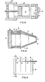
- the nozzle portion 26 of the drop-on-demand ink jet printing apparatus comprises a converging nozzle. As shown in Figure 1, the nozzle has an entrance dimension d 1 , which is larger than the exit dimension d 2 .
- the nozzle shown in the drawing has a substantially linear taper in the dimension of the nozzle along its physical length I however, other tapers such as a horn configuration would also be suitable.
- the flow through the nozzle is in the direction from the larger opening to the smaller opening, as shown by the arrow.
- the effective viscous length l d2 of a converging nozzle can be calculated as where d 1 , d 2 are the dimensions at the entrance and exit of the converging section, respectively, and I is the physical length of the nozzle (see Figure 1).
- d 1 , d 2 are the dimensions at the entrance and exit of the converging section, respectively
- I is the physical length of the nozzle (see Figure 1).
- the operation was superior in other ways as well.
- air ingestion into the nozzle is completely inhibited and the stream stability is improved so that a stream of drops of equal size and spacing can be produced.
- the stream directionality is improved, and the jet velocity is easily increased which is essential for high speed printing.
- the nozzle can be operated at any frequency in the frequency spectrum up to 120 kHz without jet failure, and the nozzle can be operated up to 80 kHz drop-on-demand drop production rate in high resolution printing operation.
- the converging nozzle can be produced by any suitable technique.
- the preferred technique for producing a converging nozzle is by anisotropically etching the nozzle in a silicon substrate. This technique will be described with reference to the embodiment of the drop-on-demand print head shown in Figure 4.
- the print head comprises cylindrical transducer member 60 closed at one end by a nozzle plate 62, having formed therein nozzle portion 64. The other end of the transducer is fixed to body member 66.
- a suitable voltage drive pulse i.e.
- transducer 60 is deflected to the position shown dotted in Figure 4 to cause a single drop of ink 78 to be expelled out through nozzle portion 64.
- Energisation of the transducer with a drive pulse of less than the predetermined threshold amplitude does not cause a drop to be ejected so drops can be selected by varying the amplitude of a continuous drive signal.
- Nozzle plate 62 comprises a silicon substrate formed of single crystal material oriented with the (100) planes parallel to the front surface.
- the front surface 68 and the rear surface 70 of the nozzle plate are coated with etchant masking material.
- An aperture is made in the masking material on the rear surface of the nozzle plate.
- the nozzle plate is then subjected to a suitable anisotropic etching solution such as a water, amine, pyro- catechol etchant, for example.
- a suitable anisotropic etching solution such as a water, amine, pyro- catechol etchant, for example.
- the (111) plane is a slow etch plane in single crystal silicon.
- the nozzle is etched in the form of a truncated pyramid type opening with a square entrance aperture, tapered sides, and a smaller square exit aperture.
- the tapered sides form an angle a of 54.7° to the front surface since the etching is along the crystal planes of the silicon
- the silicon nozzle plate was about 1.27x 10- 2 cms, i.e. five mils thick and the nozzle plate was etched to produce about a 26x10- 6 sq.cm. i.e. a two mil square, exit aperture.
- the print head including the above-described nozzle plate, produced reliable drop-on-demand operation up to a drop production rate of 60 kHz at a resolution of about 95 pels/cm i.e. 240 pels/inch. This resolution is considered high resolution printing since it produces print resolution approaching that of engraved type. However, the print quality began to decline at drop production rates over 40 kHz.
- inks having a viscosity with a range from about 15 centipoise up to 100 centipoise worked to produce ink drops in a drop-on-demand mode, and the preferred. range of viscosity was from 20 to 40 centipoise.
- Figures 5 and 6 show a print head array 40 comprising forty print heads 42 arranged in four rows 44 with corresponding orifices 46 offset so that a line of printing can be produced at a resolution approaching engraved type as the print head moves across a print sheet.
- Each of the print heads 42 comprises a hollow cylindrical piezoelectric transducer 48 which forms an ink chamber 50 to which ink is supplied from common reservoir 52.
- a housing 54 is provided which includes a tapered channel 56 for each print head which transmits ink from ink chamber 50 to the corresponding orifice 46 in nozzle plate 58.
- the orifices are strongly convergent nozzles, as indicated in Figure 6.
- nozzle plate 58 comprises a single crystal silicon substrate and orifices are formed by anisotropic etching as described above to form square orifices in nozzle plate 58, as shown in Figure 5.
- a forty nozzle array similar to that shown in Figures 5 and 6 was constructed with about a 26x10-6 sq.cm. i.e. a 2 mil square nozzles.
- This array can be operated to produce printing at a resolution of about 95 pels/cm i.e. 240 pels/inch at a drop-on-demand drop production rate of up to 40 kHz.
- the array operated successfully with ink having a viscosity down to 15 centipoise and up to 100 centipoise. However, the optimum range for the viscosity was 20 to 40 centipoise.
Landscapes
- Particle Formation And Scattering Control In Inkjet Printers (AREA)
Claims (11)
Applications Claiming Priority (2)
| Application Number | Priority Date | Filing Date | Title |
|---|---|---|---|
| US27498981A | 1981-06-18 | 1981-06-18 | |
| US274989 | 1988-11-22 |
Publications (2)
| Publication Number | Publication Date |
|---|---|
| EP0067948A1 EP0067948A1 (de) | 1982-12-29 |
| EP0067948B1 true EP0067948B1 (de) | 1985-08-14 |
Family
ID=23050440
Family Applications (1)
| Application Number | Title | Priority Date | Filing Date |
|---|---|---|---|
| EP19820103883 Expired EP0067948B1 (de) | 1981-06-18 | 1982-05-05 | Methode und Apparat zum Produzieren von Flüssigkeitstropfen auf Befehl |
Country Status (4)
| Country | Link |
|---|---|
| EP (1) | EP0067948B1 (de) |
| JP (1) | JPS57208262A (de) |
| CA (1) | CA1191391A (de) |
| DE (1) | DE3265382D1 (de) |
Families Citing this family (5)
| Publication number | Priority date | Publication date | Assignee | Title |
|---|---|---|---|---|
| US4587534A (en) * | 1983-01-28 | 1986-05-06 | Canon Kabushiki Kaisha | Liquid injection recording apparatus |
| JP3317308B2 (ja) * | 1992-08-26 | 2002-08-26 | セイコーエプソン株式会社 | 積層型インクジェット記録ヘッド、及びその製造方法 |
| JP2721127B2 (ja) * | 1994-03-03 | 1998-03-04 | 富士通株式会社 | インクジェットヘッド |
| DE102005015503A1 (de) * | 2005-04-05 | 2006-10-12 | Heger Gmbh European Diamand Tools | Trennschleifscheibe |
| CN117283989B (zh) * | 2023-10-30 | 2024-06-11 | 武汉国创科光电装备有限公司 | 一种用于喷墨打印的阵列化电流体喷印方法及装置 |
Family Cites Families (4)
| Publication number | Priority date | Publication date | Assignee | Title |
|---|---|---|---|---|
| US3683212A (en) * | 1970-09-09 | 1972-08-08 | Clevite Corp | Pulsed droplet ejecting system |
| US3921916A (en) * | 1974-12-31 | 1975-11-25 | Ibm | Nozzles formed in monocrystalline silicon |
| DE2728657A1 (de) * | 1977-06-24 | 1979-01-04 | Siemens Ag | Duesenplatte fuer tintenschreibeinrichtungen |
| DE2846844A1 (de) * | 1978-10-27 | 1980-05-08 | Philips Patentverwaltung | Tintenstrahldrucker |
-
1982
- 1982-03-18 JP JP4182982A patent/JPS57208262A/ja active Pending
- 1982-03-23 CA CA000399064A patent/CA1191391A/en not_active Expired
- 1982-05-05 EP EP19820103883 patent/EP0067948B1/de not_active Expired
- 1982-05-05 DE DE8282103883T patent/DE3265382D1/de not_active Expired
Also Published As
| Publication number | Publication date |
|---|---|
| EP0067948A1 (de) | 1982-12-29 |
| CA1191391A (en) | 1985-08-06 |
| DE3265382D1 (en) | 1985-09-19 |
| JPS57208262A (en) | 1982-12-21 |
Similar Documents
| Publication | Publication Date | Title |
|---|---|---|
| US4475113A (en) | Drop-on-demand method and apparatus using converging nozzles and high viscosity fluids | |
| EP0510648B1 (de) | Hochfrequenzdruckvorrichtung | |
| US3946398A (en) | Method and apparatus for recording with writing fluids and drop projection means therefor | |
| US4339763A (en) | Apparatus for recording with writing fluids and drop projection means therefor | |
| EP0194852B1 (de) | Antriebssystem für ein Tintenstrahlgerät | |
| US4580148A (en) | Thermal ink jet printer with droplet ejection by bubble collapse | |
| US4216483A (en) | Linear array ink jet assembly | |
| EP0063853B1 (de) | Tintenstrahldruckkopf, in dem Druck- und Potentialunterschiede angewendet werden | |
| US5170177A (en) | Method of operating an ink jet to achieve high print quality and high print rate | |
| EP0720534B1 (de) | Auf abruf arbeitende hochfrequenz-tintenstrahldruckvorrichtung | |
| EP0025877A1 (de) | Tintenstrahldruckkopf und Tintenstrahldrucker | |
| JPH0331142B2 (de) | ||
| US4420764A (en) | Ink jet printer head | |
| USRE45494E1 (en) | System and methods for fluid drop ejection | |
| JP5315980B2 (ja) | 液滴吐出装置、液滴吐出方法および画像形成装置 | |
| EP0090663A1 (de) | Methode und Apparat zum Ausstossen von Tintentröpfchen | |
| CA1160905A (en) | Arrangement for a printing head in ink mosaic printing devices | |
| EP1216834B1 (de) | Tintenstrahldrucken mit auf Abruf arbeitende Techniken für Drucken mit kontinuierlichen Tönen | |
| JP2002144570A (ja) | 液滴吐出方法、画像形成方法、液体吐出装置およびヘッド | |
| EP0067948A1 (de) | Methode und Apparat zum Produzieren von Flüssigkeitstropfen auf Befehl | |
| EP0900656A2 (de) | Drucken mit Tinte mit Trennung von Tropfen mit veränderlichem Volumen | |
| JPH05330045A (ja) | 記録ヘッドおよび該記録ヘッドを備えるインクジェット記録装置 | |
| JP3581504B2 (ja) | インクジェットプリントヘッド | |
| GB1598779A (en) | Ink-jet printers | |
| JP2002127403A (ja) | インクジェットプリントヘッドの作動方法 |
Legal Events
| Date | Code | Title | Description |
|---|---|---|---|
| PUAI | Public reference made under article 153(3) epc to a published international application that has entered the european phase |
Free format text: ORIGINAL CODE: 0009012 |
|
| AK | Designated contracting states |
Designated state(s): DE FR GB IT |
|
| 17P | Request for examination filed |
Effective date: 19830420 |
|
| ITF | It: translation for a ep patent filed | ||
| GRAA | (expected) grant |
Free format text: ORIGINAL CODE: 0009210 |
|
| AK | Designated contracting states |
Designated state(s): DE FR GB IT |
|
| REF | Corresponds to: |
Ref document number: 3265382 Country of ref document: DE Date of ref document: 19850919 |
|
| ET | Fr: translation filed | ||
| PLBE | No opposition filed within time limit |
Free format text: ORIGINAL CODE: 0009261 |
|
| STAA | Information on the status of an ep patent application or granted ep patent |
Free format text: STATUS: NO OPPOSITION FILED WITHIN TIME LIMIT |
|
| 26N | No opposition filed | ||
| ITTA | It: last paid annual fee | ||
| REG | Reference to a national code |
Ref country code: FR Ref legal event code: GC |
|
| REG | Reference to a national code |
Ref country code: GB Ref legal event code: 732 |
|
| REG | Reference to a national code |
Ref country code: FR Ref legal event code: TP |
|
| ITPR | It: changes in ownership of a european patent |
Owner name: CESSIONE;LEXMARK INTERNATIONAL INC. |
|
| PGFP | Annual fee paid to national office [announced via postgrant information from national office to epo] |
Ref country code: FR Payment date: 19920408 Year of fee payment: 11 |
|
| PGFP | Annual fee paid to national office [announced via postgrant information from national office to epo] |
Ref country code: DE Payment date: 19920410 Year of fee payment: 11 |
|
| ITPR | It: changes in ownership of a european patent |
Owner name: PEGNO;J.P. MORGAN DELAWARE |
|
| PGFP | Annual fee paid to national office [announced via postgrant information from national office to epo] |
Ref country code: GB Payment date: 19920429 Year of fee payment: 11 |
|
| PG25 | Lapsed in a contracting state [announced via postgrant information from national office to epo] |
Ref country code: GB Effective date: 19930505 |
|
| GBPC | Gb: european patent ceased through non-payment of renewal fee |
Effective date: 19930505 |
|
| PG25 | Lapsed in a contracting state [announced via postgrant information from national office to epo] |
Ref country code: FR Effective date: 19940131 |
|
| PG25 | Lapsed in a contracting state [announced via postgrant information from national office to epo] |
Ref country code: DE Effective date: 19940201 |
|
| REG | Reference to a national code |
Ref country code: FR Ref legal event code: ST |