EP0067955A1 - Verfahren und Vorrichtung zur Herstellung von Formmasken - Google Patents
Verfahren und Vorrichtung zur Herstellung von Formmasken Download PDFInfo
- Publication number
- EP0067955A1 EP0067955A1 EP82104062A EP82104062A EP0067955A1 EP 0067955 A1 EP0067955 A1 EP 0067955A1 EP 82104062 A EP82104062 A EP 82104062A EP 82104062 A EP82104062 A EP 82104062A EP 0067955 A1 EP0067955 A1 EP 0067955A1
- Authority
- EP
- European Patent Office
- Prior art keywords
- model
- sand
- fluid container
- air
- model plate
- Prior art date
- Legal status (The legal status is an assumption and is not a legal conclusion. Google has not performed a legal analysis and makes no representation as to the accuracy of the status listed.)
- Granted
Links
- 238000000034 method Methods 0.000 title claims abstract description 14
- 238000009434 installation Methods 0.000 title 1
- 239000004576 sand Substances 0.000 claims abstract description 24
- 239000012530 fluid Substances 0.000 claims description 19
- 230000015572 biosynthetic process Effects 0.000 claims description 9
- 239000000945 filler Substances 0.000 claims description 6
- 238000004519 manufacturing process Methods 0.000 claims description 5
- 239000003110 molding sand Substances 0.000 claims description 5
- 238000001816 cooling Methods 0.000 claims description 3
- 239000000463 material Substances 0.000 claims description 2
- 229920001187 thermosetting polymer Polymers 0.000 claims description 2
- 238000000465 moulding Methods 0.000 abstract description 4
- 230000000630 rising effect Effects 0.000 abstract 1
- 210000003739 neck Anatomy 0.000 description 4
- 239000003344 environmental pollutant Substances 0.000 description 3
- 231100000719 pollutant Toxicity 0.000 description 3
- 238000007789 sealing Methods 0.000 description 2
- 239000011230 binding agent Substances 0.000 description 1
- 238000007664 blowing Methods 0.000 description 1
- 235000015115 caffè latte Nutrition 0.000 description 1
- 239000011248 coating agent Substances 0.000 description 1
- 238000000576 coating method Methods 0.000 description 1
- 238000005516 engineering process Methods 0.000 description 1
- 238000005243 fluidization Methods 0.000 description 1
- 238000010438 heat treatment Methods 0.000 description 1
- 230000001105 regulatory effect Effects 0.000 description 1
Images
Classifications
-
- B—PERFORMING OPERATIONS; TRANSPORTING
- B22—CASTING; POWDER METALLURGY
- B22C—FOUNDRY MOULDING
- B22C13/00—Moulding machines for making moulds or cores of particular shapes
- B22C13/08—Moulding machines for making moulds or cores of particular shapes for shell moulds or shell cores
Definitions
- the invention relates to a method for producing molding masks for foundry applications from a thermosetting molding sand on a heatable model and to an apparatus for carrying out the method. It refers to all suitable types of sand, the corresponding binders, e.g. in the form of a coating of the individual grains of sand or by a moisture-binding admixture to the sand.
- the invention has for its object to simplify and accelerate the manufacturing process and also to offer suitable measures for removing the pollutants. Use in a higher-level production process should also be possible or guaranteed.
- the object is mainly achieved by heating the model with the mold surface facing downward in a sand volume fluidized by an increasing air flow until a mold mask is formed.
- a further contribution to the solution is that air is removed from the interior via a model plate carrying the model during mask formation.
- a suitable method for this apparatus includes a fluid container with a bottom flask equipped with air supply openings and the fluid container can be lifted final model p latte with air outlet openings.
- the hanging arrangement of the model in the fluidized sand volume allows the finished molding mask to be lifted up with the model, while the excess, not hardened molding sand remains in its position, in particular in a fluid container.
- the thickness and strength of the resulting mask can be adjusted in the usual way by the model temperature and the curing time and, moreover, according to the invention by the density of the fluidized sand, which can be regulated as a function of the air flow.
- a particular possibility of influencing the mask formation arises if a model plate carrying the model or a bottom piston in a fluid container are brought closer to one another during the mask formation, in particular by lifting the bottom piston. Lowering the model plate and lifting the bottom piston is equivalent in terms of process technology. When the bottom piston can be raised, the model plate can then be designed in a particularly simple manner in the form of a lid on the fluid container.
- the fluidization of the sand takes place by blowing air into the bottom area of a fluid container or other device, in particular through openings in the bottom piston, the air being able to escape through openings in the model plate, in particular in the vicinity of the model, through openings of a suitable size.
- discharge or suction openings can also advantageously be present in the model area itself, in order to accelerate or improve the mask formation.
- the supply of air continues to take place during the removal of the molding mask and the refilling of the processed sand.
- One embodiment which is particularly suitable for solving the task provides a model plate which can be connected in a sealing manner to the container and on which the pollutants can emerge collectively at a single suction opening.
- the bottom piston is preferably designed with a compressed air connection opening.
- a bottom flask made of an air-permeable sintered material is preferred according to the invention.
- the sand can be refilled with the lid lifted off in the usual way by pouring in from above or, in a preferred automatic manner, by slipping over lateral filler necks in the fluid container.
- the dumping height is automatically set by the height of the inlet openings in combination with a lowering of the bottom piston.
- the sand in the fluid container normally remains in a fluidized state.
- the filler necks are connected to a sand reservoir located higher up via pipes that continuously drop from it.
- a cooling channel in the fluid container in the upper area prevents heat transfer from the heated model and the model plate to the fluid container, so that hardening of the sand contained therein is precluded.
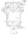
- the figure shows an embodiment of a device according to the invention.
- a model 1 is attached with the mold surface facing downward to a model plate 2 which has air outlet openings 3 in the form of slot nozzles in the vicinity of the model.
- the model plate 2 has an air suction box 15 with a suction nozzle 16.
- the model plate 2 serves as a removable, ins Special hinged lid of a fluid container 10, which has a cooling channel 4 in the upper region.
- Below the model in the situation shown, there is a free space 5 before the mask formation begins.
- the fluidized sand volume 7 has automatically increased to the level of filler necks arranged on both sides.
- the filler neck 6 are connected to a sand reservoir, not shown, via falling channels.
- An overpressure box 9 is built underneath the bottom piston 11, which forms a pressure chamber 8 with it and is supplied via a flexible pressure line 14.
- the bottom piston 11 with the overpressure box 9 can be moved in height by means of an adjusting device 13, which is not described in more detail, so that the fluidized sand can be moved in a desired manner to the model constantly or periodically to the extent that a density and hardening-controlled form mask is produced.
Landscapes
- Engineering & Computer Science (AREA)
- Mechanical Engineering (AREA)
- Casting Devices For Molds (AREA)
Abstract
Description
- Die Erfindung betrifft ein Verfahren zur Herstellung von Formmasken für Gießereianwendungen aus einem thermisch aushärtenden Formsand an einem beheizbaren Modell sowie eine Vorrichtung zur Durchführung des Verfahrens. Es bezieht sich auf alle hierfür geeigneten Sandarten, die entsprechende Bindemittel, z.B. in Form einer Umhüllung der einzelnen Sandkörner oder durch eine feuchtigkeitsbindende Zumischung zum Sand aufweisen.
- Die Formmaskenherstellung mit thermisch aushärtendem Formsand nach dem sog. Croningverfahren ist allgemein bekannt. Die bisher verwendeten Verfahren weisen Nachteile im Hinblick auf die Befreiung des fertigen Modells vom nicht ausgehärteten Formsand sowie unter dem Gesichtspunkt der unbefriedigenden Führung bei der Aushärtung entstehender Schadstoffe auf. Weiterhin wird der große verfahrenstechnische und bauliche Aufwand als nachteilig empfunden.
- Der Erfindung liegt die Aufgabe zugrunde, den Fertigungsablauf zu vereinfachen und zu beschleunigen und des weiteren geeignete Maßnahmen zur Abführung der Schadstoffe anzubieten. Dabei soll auch der Einsatz in einen übergeordneten Fertigungsablauf möglich bzw. gewährleistet sein.
- Die Aufgabe wird in der Hauptsache dadurch gelöst, daß das Modell mit nach unten gekehrter Formoberfläche in einem durch eine steigende Luftströmung fluidisierten Sandvolumen bis zur Ausbildung einer Formmaske erwärmt wird. Weiter trägt zur Lösung bei, daß während der Maskenbildung aus dem Innenraum Luft über eine das Modell tragende Modellplatte abgeführt wird. Eine für dieses Verfahren geeignete Vorrichtung weist einen Fluidbehälter mit einem Bodenkolben mit Luftzufuhröffnungen und einer den Fluidbehälter abschließenden abhebbaren Modellplatte mit Luftaustrittsöffnungen auf.
- Die hängende Anordnung des Modells im fluidisierten Sandvolumen gestattet es, die fertige Formmaske mit dem Modell nach oben abzuheben, während der überschüssige, nicht erhärtete Formsand in seiner Position insbesondere in einem Fluidbehälter verbleibt. Die Dicke und Festigkeit der entstehenden Formmaske läßt sich in üblicher Weise durch die Modelltemperatur und die Aushärtzeit sowie darüber hinaus nach der Erfindung durch die in Abhängigkeit von der Luftströmung regelbare Dichte des fluidisierten Sandes einstellen.
- Eine besondere Einflußmöglichkeit auf die Maskenbildung ergibt sich, wenn eine das Modell tragende Modellplatte oder ein Bodenkolben in einem Fluidbehälter während der Maskenbildung einander angenähert werden, insbesondere durch Anheben des Bodenkolbens. Das Absenken der Modellplatte und Anheben des Bodenkolbens ist verfahrenstechnisch gesehen gleichwertig. Bei anhebbarem Bodenkolben kann die Modellplatte dann in besonders einfacher Weise in Form eines Deckels am Fluidbehälter ausgeführt werden.
- Das Fluidisieren des Sandes findet durch Lufteinblasen im Bodenbereich eines Fluidbehälters oder einer sonstigen Vorrichtung insbesondere durch Öffnungen in dem Bodenkolben statt, wobei die Luft durch Öffnungen in der Modellplatte, insbesondere in der Umgebung des Modells durch Öffnungen angemessener Größe entweichen kann. Je nach Modellform können in vorteilhafter Weise auch im Modellbereich selbst Abführ- bzw. Absaugöffnungen vorhanden sein, um die Maskenbildung zu beschleunigen bzw. zu verbessern. Die Zufuhr der Luft erfolgt im Normalfall auch während der Entnahme der Formmaske und dem Nachfüllen des verarbeiteten Sandes dauernd weiter.
- Eine zur Lösung der Aufgabe besonders geeignete Ausführung sieht eine mit dem Behälter dichtend verbindbare Modellplatte vor, an der an einer einzigen Absaugöffnung die Schadstoffe gesammelt austreten können. In gleichartiger Weise ist vorzugsweise der Bodenkolben mit einer Druckluftanschlußöffnung ausgeführt. Anstelle einer Vielzahl von kleinen Öffnungen in dem Bodenkolben, die durch Sandverschluß gefährdet sind, ist erfindungsgemäß ein Bodenkolben aus einem luftdurchlässigen Sintermaterial vorzuziehen.
- Das Nachfüllen des Sandes kann bei abgehobenem Dekkel in üblicher Weise durch Nachschütten von oben oder aber in bevorzugter selbsttätiger Art durch Nachrutschen über seitliche Einfüllstutzen im Fluidbehälter erfolgen. Die Schütthöhe stellt sich dabei automatisch durch die Höhe der.Eintrittsöffnungen in Kombination mit einer Absenkung des Bodenkolbens ein. Der Sand im Fluidbehälter bleibt dabei normalerweise in fluidisiertem Zustand. Die Einfüllstutzen sind mit einem höher gelegenen Sandvorratsbehälter über von diesem stetig abfallende Leitungen verbunden.
- Ein Kühlkanal im Fluidbehälter im oberen Bereich verhindert erfindungsgemäß einen Wärmeübergang vom erwärmten Modell und der Modellplatte auf den Fluidbehälter, so daß eine Erhärtung des darin befindlichen Sandes ausgeschlossen ist.
- Die Figur zeigt ein Ausführungsbeispiel einer erfindungsgemäßen Vorrichtung.
- Ein Modell 1 ist mit nach unten gekehrter Formoberfläche an einer Modellplatte 2 befestigt, die als Schlitzdüsen ausgebildete Luftaustrittsöffnungen 3 in Nähe des Modells aufweist. Der Modellplatte 2 ist ein Luftabsaugkasten 15 mit einem Absaugstutzen 16 aufgesetzt. Die Modellplatte 2 dient als abhebbarer, insbesondere abklappbarer Deckel eines Fluidbehälters 10, der im oberen Bereich einen Kühlkanal 4 aufweist. Unterhalb des Modells befindet sich in der dargestellten Situation vor dem Beginn der Maskenbildung ein Freiraum 5. Das fluidisierte Sandvolumen 7 ist selbsttätig bis zur Höhe von beidseitig angeordneten Einfüllstutzen angestiegen. Die Einfüllstutzen 6 sind mit einem nicht dargestellten Sandvorratsbehälter über fallende Kanäle verbunden. Der höhenbewegliche,mit einer Vielzahl von Luftzufuhröffnungen 17 versehene Bodenkolben 11 ist gegenüber dem Fluidbehälter 10 durch eine Dichtlippe 12 abgedichtet. Dem Bodenkolben 11 ist ein Überdruckkasten 9 untergebaut, der mit diesem einen Druckraum 8 bildet und über eine flexible Druckleitung 14 versorgt wird. Der Bodenkolben 11 mit dem Überdruckkasten 9 ist mittels einer nicht näher ausgeführten Verstellvorrichtung 13 höhenbeweglich, so daß der fluidisierte Sand in gewünschter Weise soweit an das Modell konstant oder periodisch heranbewegt werden kann, daß einedichte- und aushärtungskontrollierte Formmaske entsteht.
Claims (16)
dadurch gekennzeichnet, daß vor der Maskenbildung ein Innenraum unter dem Modell (1) unter Wahrung eines Freiraums (5) mit Sand aufgeschüttet wird und daß während der Maskenbildung der Innenraum unter Annäherung seines Bodenkolbens (11) und der Modellplatte (2) aneinander verkleinert wird.
Priority Applications (1)
| Application Number | Priority Date | Filing Date | Title |
|---|---|---|---|
| AT82104062T ATE11744T1 (de) | 1981-06-19 | 1982-05-11 | Verfahren und vorrichtung zur herstellung von formmasken. |
Applications Claiming Priority (2)
| Application Number | Priority Date | Filing Date | Title |
|---|---|---|---|
| DE19813124024 DE3124024A1 (de) | 1981-06-19 | 1981-06-19 | Verfahren und vorrichtung zur herstellung von formmasken |
| DE3124024 | 1981-06-19 |
Publications (2)
| Publication Number | Publication Date |
|---|---|
| EP0067955A1 true EP0067955A1 (de) | 1982-12-29 |
| EP0067955B1 EP0067955B1 (de) | 1985-02-13 |
Family
ID=6134877
Family Applications (1)
| Application Number | Title | Priority Date | Filing Date |
|---|---|---|---|
| EP82104062A Expired EP0067955B1 (de) | 1981-06-19 | 1982-05-11 | Verfahren und Vorrichtung zur Herstellung von Formmasken |
Country Status (3)
| Country | Link |
|---|---|
| EP (1) | EP0067955B1 (de) |
| AT (1) | ATE11744T1 (de) |
| DE (2) | DE3124024A1 (de) |
Citations (4)
| Publication number | Priority date | Publication date | Assignee | Title |
|---|---|---|---|---|
| GB725455A (en) * | 1952-04-05 | 1955-03-02 | Gen Motors Corp | Method and apparatus for forming casting moulds or cores |
| DE1141053B (de) * | 1956-03-20 | 1962-12-13 | Emery I Valyi | Vorrichtung zum Herstellen von Formmasken, insbesondere fuer Giessereizwecke |
| FR1587183A (de) * | 1967-10-23 | 1970-03-13 | ||
| US4067380A (en) * | 1973-06-28 | 1978-01-10 | British Cast Iron Research Association | Making foundry moulds |
Family Cites Families (1)
| Publication number | Priority date | Publication date | Assignee | Title |
|---|---|---|---|---|
| JPS5641044A (en) * | 1979-09-10 | 1981-04-17 | Dependable Fordath Inc | Method of casting sheel mold |
-
1981
- 1981-06-19 DE DE19813124024 patent/DE3124024A1/de not_active Withdrawn
-
1982
- 1982-05-11 EP EP82104062A patent/EP0067955B1/de not_active Expired
- 1982-05-11 AT AT82104062T patent/ATE11744T1/de not_active IP Right Cessation
- 1982-05-11 DE DE8282104062T patent/DE3262295D1/de not_active Expired
Patent Citations (4)
| Publication number | Priority date | Publication date | Assignee | Title |
|---|---|---|---|---|
| GB725455A (en) * | 1952-04-05 | 1955-03-02 | Gen Motors Corp | Method and apparatus for forming casting moulds or cores |
| DE1141053B (de) * | 1956-03-20 | 1962-12-13 | Emery I Valyi | Vorrichtung zum Herstellen von Formmasken, insbesondere fuer Giessereizwecke |
| FR1587183A (de) * | 1967-10-23 | 1970-03-13 | ||
| US4067380A (en) * | 1973-06-28 | 1978-01-10 | British Cast Iron Research Association | Making foundry moulds |
Also Published As
| Publication number | Publication date |
|---|---|
| DE3262295D1 (en) | 1985-03-28 |
| EP0067955B1 (de) | 1985-02-13 |
| DE3124024A1 (de) | 1982-12-30 |
| ATE11744T1 (de) | 1985-02-15 |
Similar Documents
| Publication | Publication Date | Title |
|---|---|---|
| DE69405588T2 (de) | Verfahren und vorrichtung zum ausgleichen von schrumpf beim metallgiessen | |
| DE3423199C1 (de) | Einrichtung fuer die Durchfuehrung des Vollformgiessverfahrens | |
| DE2622552B2 (de) | Formkasten zur Herstellung von Gußstücken | |
| DE832936C (de) | Verfahren und Vorrichtung zur Herstellung von Formmasken oder Kernen | |
| EP0067955B1 (de) | Verfahren und Vorrichtung zur Herstellung von Formmasken | |
| DE557503C (de) | Verfahren und Formmaschine zum Fuellen von Form- und Kernkaesten mit Formsand durch Druckluft | |
| EP1786576B1 (de) | Verfahren und vorrichtung zum giessen von metallschmelze | |
| DE10144193C1 (de) | Verfahren und Formschießmaschine zum Herstellen von Formteilen, wie Gießkernen, für Gießformen zum Vergießen von Metallschmelze | |
| DE69103826T2 (de) | Verfahren und Vorrichtung zur Durchführung flüssigen Metalls in eine Sandgiessform mittels Niederdruck. | |
| DE2444377B2 (de) | Verfahren und vorrichtung zur herstellung von formteilen fuer giessereien | |
| DE1301440B (de) | Verfahren und Vorrichtung zur Herstellung von Gussstuecken | |
| DE1076901B (de) | Verfahren und Einrichtung zum Herstellen von Giessformen | |
| US2997757A (en) | Foundry mold | |
| DE865938C (de) | Verfahren und Vorrichtung zur Herstellung von Giessformen | |
| EP0126269B1 (de) | Verfahren und Vorrichtung zum Herstellen von Giessformen | |
| DE10321532A1 (de) | Verfahren und Formmaschine zur Herstellung kastengebundener Sandformen | |
| DE1155883B (de) | Verfahren zur Herstellung von Kernen und Formen fuer Giessereizwecke | |
| DE2926906A1 (de) | Isolierspeiser-einsatzhuelse | |
| US1337780A (en) | lonskey | |
| DE1118405B (de) | Formmaschine zur pneumatischen Herstellung von Giessereikernen und Giessereiformen | |
| US4143700A (en) | Angled molding machine | |
| DE444050C (de) | Verfahren und Vorrichtung zum Einleiten des Giessmetalls in Schleudergussformen | |
| DE8606530U1 (de) | Vorrichtung zum Herstellen von Gießformen | |
| US3293701A (en) | Automaton for manufacturing shell half-molds from sand and resin compositions | |
| AT44053B (de) | Vorrichtung zum Entnehmen bemessener Glasmengen aus einem Schmelzofen. |
Legal Events
| Date | Code | Title | Description |
|---|---|---|---|
| PUAI | Public reference made under article 153(3) epc to a published international application that has entered the european phase |
Free format text: ORIGINAL CODE: 0009012 |
|
| AK | Designated contracting states |
Designated state(s): AT BE CH DE FR GB IT LI NL SE |
|
| 17P | Request for examination filed |
Effective date: 19830120 |
|
| ITF | It: translation for a ep patent filed | ||
| GRAA | (expected) grant |
Free format text: ORIGINAL CODE: 0009210 |
|
| AK | Designated contracting states |
Designated state(s): AT BE CH DE FR GB IT LI NL SE |
|
| REF | Corresponds to: |
Ref document number: 11744 Country of ref document: AT Date of ref document: 19850215 Kind code of ref document: T |
|
| REF | Corresponds to: |
Ref document number: 3262295 Country of ref document: DE Date of ref document: 19850328 |
|
| ET | Fr: translation filed | ||
| PLBE | No opposition filed within time limit |
Free format text: ORIGINAL CODE: 0009261 |
|
| STAA | Information on the status of an ep patent application or granted ep patent |
Free format text: STATUS: NO OPPOSITION FILED WITHIN TIME LIMIT |
|
| 26N | No opposition filed | ||
| PGFP | Annual fee paid to national office [announced via postgrant information from national office to epo] |
Ref country code: AT Payment date: 19860409 Year of fee payment: 5 |
|
| PGFP | Annual fee paid to national office [announced via postgrant information from national office to epo] |
Ref country code: NL Payment date: 19870531 Year of fee payment: 6 |
|
| PG25 | Lapsed in a contracting state [announced via postgrant information from national office to epo] |
Ref country code: DE Effective date: 19890201 |
|
| PG25 | Lapsed in a contracting state [announced via postgrant information from national office to epo] |
Ref country code: GB Effective date: 19890511 Ref country code: AT Effective date: 19890511 |
|
| PG25 | Lapsed in a contracting state [announced via postgrant information from national office to epo] |
Ref country code: SE Effective date: 19890512 |
|
| PG25 | Lapsed in a contracting state [announced via postgrant information from national office to epo] |
Ref country code: LI Effective date: 19890531 Ref country code: CH Effective date: 19890531 Ref country code: BE Effective date: 19890531 |
|
| PG25 | Lapsed in a contracting state [announced via postgrant information from national office to epo] |
Ref country code: NL Effective date: 19891201 |
|
| GBPC | Gb: european patent ceased through non-payment of renewal fee | ||
| NLV4 | Nl: lapsed or anulled due to non-payment of the annual fee | ||
| PG25 | Lapsed in a contracting state [announced via postgrant information from national office to epo] |
Ref country code: FR Free format text: LAPSE BECAUSE OF NON-PAYMENT OF DUE FEES Effective date: 19900131 |
|
| REG | Reference to a national code |
Ref country code: CH Ref legal event code: PL |
|
| REG | Reference to a national code |
Ref country code: FR Ref legal event code: ST |
|
| EUG | Se: european patent has lapsed |
Ref document number: 82104062.3 Effective date: 19900412 |