EP0067985A2 - Farbbandantriebsanordnung für einen Drucker - Google Patents
Farbbandantriebsanordnung für einen Drucker Download PDFInfo
- Publication number
- EP0067985A2 EP0067985A2 EP82104813A EP82104813A EP0067985A2 EP 0067985 A2 EP0067985 A2 EP 0067985A2 EP 82104813 A EP82104813 A EP 82104813A EP 82104813 A EP82104813 A EP 82104813A EP 0067985 A2 EP0067985 A2 EP 0067985A2
- Authority
- EP
- European Patent Office
- Prior art keywords
- ribbon
- drive
- reel
- blade
- edge
- Prior art date
- Legal status (The legal status is an assumption and is not a legal conclusion. Google has not performed a legal analysis and makes no representation as to the accuracy of the status listed.)
- Granted
Links
Images

Classifications
-
- B—PERFORMING OPERATIONS; TRANSPORTING
- B41—PRINTING; LINING MACHINES; TYPEWRITERS; STAMPS
- B41J—TYPEWRITERS; SELECTIVE PRINTING MECHANISMS, i.e. MECHANISMS PRINTING OTHERWISE THAN FROM A FORME; CORRECTION OF TYPOGRAPHICAL ERRORS
- B41J33/00—Apparatus or arrangements for feeding ink ribbons or like character-size impression-transfer material
- B41J33/14—Ribbon-feed devices or mechanisms
- B41J33/24—Ribbon-feed devices or mechanisms with drive applied directly to ribbon
- B41J33/28—Ribbon-feed devices or mechanisms with drive applied directly to ribbon by mechanism pulling or gripping the ribbon
Definitions
- the subject invention relates to ribbon advancing apparatus and more specifically to compact apparatus for advancing equal increments of a ribbon or tape irrespective of the outer diameter of the ribbon accumulated at a take-up reel.
- a known way to provide for equal increments while nonetheless retaining flanges to assure planar wrapping involves a detection of the diameter of the take-up spool and direct drive of the spool at, for example, the reel rim or core in increments corresponding to the detected diameter (see, e.g. US-A Nos 3,677,486 and 4,168, 127).
- Such a feedback approach involves considerable complexity, however.
- the often used residual solution is to use a take-up reel with flanges and set the increment to be adequate for the minimum take-up reel diameter. A degree of waste is then tolerated at other diameters.
- a reciprocating ribbon drive utilizes a specially shaped drive blade that engages the outer convolution of the spooled ribbon.
- the blade preferably, has a drive edge in the shape of an involute of a generating circle and is pivoted about a point corresponding essentially to the generating circles center.
- a biasing device such as a spring urges the blade about the pivot in a direction ' with the drive edge leading to cause engagement with the circumference of the spooled ribbon.
- the pivot axis for the drive blade is oriented to permit movement in a plane that is generally intermediate the reel flanges and the spool axis is spaced a fixed distance from the pivot axis of the drive blade.
- a clutch device is preferably applied to the flange of the spool.
- a latch is preferably provided that interacts with a structure associated with the take-up reel (e.g. a reel housing) as mounting occurs to trigger a release of the blade to an operative position.
- a structure associated with the take-up reel e.g. a reel housing
- a take-up reel 10 is arranged to. rotate about an axis 12.
- a ribbon 14 is advanced from a supply (not shown) and wraps around a core 16 to build up cylinder 20 of wrapped ribbon with an outer circumference 18.
- Planarity of the wrapped ribbon cylinder 20 is preferably maintained by two reel flanges 22 that are perpendicular to the axis 12.
- a drive blade 24, for driving the take-up reel 10, is according to the invention pivoted to rotate about an axis 25 that is parallel to the take-up reel axis 12.
- the drive blade 24 according to the invention includes a drive edge 26 that has the shape of an involute of a generating circle, e.g. the circle 28 indicated in phantom.
- an involute curve may be throught of as the locus of the end point of a ribbon that is peeled from the generating circle by pulling radially.
- a special characteristic deriving from the above described geometry involves engagement of the drive blade 24 with the ribbon outer circumference 18.
- engagement with the drive blade 24 will be tangential and the engagement point will occur along a line 30 that passes through the axis 12 and is tangential to the generating circle 28. This, of course, assumes the drive blade 24 moves in a plane parallel to and between the flanges 22 (see figure 2).
- the drive edge 26 is serrated or textured to have projections 32 that are preferably assymetrical like a sawtooth to have a tendency to "dig in” for relative motion in one direction - the direction of increasing involute radius which is consequently the direction for ribbon advance.
- the drive blade 24 is biased, as is discussed more fully below, to rotate about the axis 25 in a direction to urge the drive edge 26 into engagement with the outer circum- ..ference 18.
- the drive blade 24 By so arranging the drive blade 24, oscillation or vibration of the axis 25 in a direction generally perpendicular to the line 30 translates into an proportional amount of movement of the edge 26 at the circumference 18.
- the projections 32 For motion in a direction corresponding to advancing movement of the reel 10, the projections 32 cause the engagement point on the outer circumference 18 to move correspondingly. And, this motion is not dependent on the diameter of the circumference 18.
- the axis 25 may be pivoted to achieve, conveniently, a reciprocating motion that is a satisfactory approximation to the desired motion perpendicular to the line 30.
- a unidirectional brake 31 see figure 2 which allows the reel 10 to turn in the advance direction only.
- the brake may, for example, be a simple balde spring 33 that engages the edge of one or both reel flanges 22.
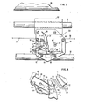
- a drive blade 24 is arranged on a carrier 50 of a printer (not shown overall) which includes a platform 51 and guide sections 52 and 54 that are recessed to reveive and slide along guide rails 56 and 58 which define a carrier path in directions parallel to the longitudinal axis of a platen 60.
- the drive blade 24 is pivotally mounted by a pin 62 (defining the axis 25) to an arm 64 of a three armed pivot 66 that rotates about a pin 67.
- a spring 68 that is compressed between-tabs 70 and 72, the drive blade is urged in the clockwise direction as viewed so as to have the drive edge 26 leading.
- a turned up arm 74 is attached by a screw 76 to the drive blade 24 to provide an operator manipulable handle for counteracting the spring 68 to permi unloading of the ribbon spool.
- the bar 78 that includes an arm 80 and an arm 82 which is connected to the arm 64 at pin 84.
- the pin 67 about which the three-armed pivot 66 rotates is mounted to the carrier by a bracket at tabs 86 (only one is visible in figure 3) which extend from a bracket 88 that is mounted to the platform 51.
- the geometry or the drive configuration is such that the drive motion causes a jamming action between the drive blade 24 and the outer circumference 18 of the ribbon cylinder 20, since the resistance of the ribbon reel 10 to advance direction motion tends to rotate the drive edge 26 to "bite" the ribbon 14 (i.e. as viewed in figure 1, the blade 24 is forced in the clockwise direction by the resistance of reel 10 when the axis 25 is moved to the right).
- a support 100 extends from the platform 51 and includes a pin 102 that is spaced from the axis 25 (see figures 1 and 2) and serves to define the axis 12 for the take-up reel 10 which is received thereon.
- the pin 102 extends through the center of the take-up reel 10 which may for convenience be supported in 'a housing 104.
- the housing 104 permits convenient mounting of the brake 33.
- a special latch 110 is provided, according to an aspect of the invention, to hold the drive blade 24 in a withdrawn position (shown in figure 3) to facilitate changing of the take-up reel 10.
- a bracket 112 is mounted to platform 51 for sliding adjustment by screws 114.
- An upturned section of the bracket 112 supports two latch members 116 and 118 that are pivotable to move between a first position with tabs 120 and 122 in the path of the drive blade 24 and a second position out of the path of the drive blade 24.
- the latch 110 When the operator withdraws the drive blade 24 by manipulating the arm 74 (figure 2), the latch 110 is tipped from the second position to the first by interaction at the upper latch member surfaces 124. At tab 126 engages the drive blade 24 and limits withdrawal thereof while when the latch bar 118, which is slidably mounted (by pins 127) to the bracket 112, reaches an end of travel. The sliding motion of the latch bar 118 moves the tab 122 to a shifted position (shown in phantom).to slow down the drive blade 24 for capture after operator release so that excessive momentum is not built up under acceleration by the spring 68.
- a tab on latch bar 116 extends to engage the housing 104 (or, alternatively, the take-up reel 10) which causes a rotation from the first to the second position releasing the drive blade 24.
- the drive blade is automatically released and is driven against the outer circumference 18 by the urging of the spring 68 to be ready to advance the ribbon 14.
Landscapes
- Impression-Transfer Materials And Handling Thereof (AREA)
- Winding Of Webs (AREA)
Applications Claiming Priority (2)
| Application Number | Priority Date | Filing Date | Title |
|---|---|---|---|
| US06/276,285 US4372697A (en) | 1981-06-22 | 1981-06-22 | Ribbon drive arrangement for a printer |
| US276285 | 1999-03-25 |
Publications (3)
| Publication Number | Publication Date |
|---|---|
| EP0067985A2 true EP0067985A2 (de) | 1982-12-29 |
| EP0067985A3 EP0067985A3 (en) | 1983-01-26 |
| EP0067985B1 EP0067985B1 (de) | 1985-05-22 |
Family
ID=23056020
Family Applications (1)
| Application Number | Title | Priority Date | Filing Date |
|---|---|---|---|
| EP82104813A Expired EP0067985B1 (de) | 1981-06-22 | 1982-06-02 | Farbbandantriebsanordnung für einen Drucker |
Country Status (5)
| Country | Link |
|---|---|
| US (1) | US4372697A (de) |
| EP (1) | EP0067985B1 (de) |
| JP (1) | JPS57212087A (de) |
| CA (1) | CA1169378A (de) |
| DE (1) | DE3263729D1 (de) |
Families Citing this family (3)
| Publication number | Priority date | Publication date | Assignee | Title |
|---|---|---|---|---|
| US4632582A (en) * | 1985-02-22 | 1986-12-30 | Centronics Data Computer Corp. | Ribbon feed mechanism providing a constant relative velocity between ribbon and print head |
| US5328116A (en) * | 1992-06-12 | 1994-07-12 | Nikka Kabushiki Kaisha | Regulated length take-up device |
| US5354138A (en) * | 1992-12-02 | 1994-10-11 | General Ribbon Corporation | Self adjusting, low torque ribbon drive system |
Family Cites Families (8)
| Publication number | Priority date | Publication date | Assignee | Title |
|---|---|---|---|---|
| US3349887A (en) * | 1964-12-28 | 1967-10-31 | Ibm | Ribbon mechanism |
| US3548994A (en) * | 1968-06-28 | 1970-12-22 | Singer Co | Proportional carbon ribbon feed mechanism |
| US3604549A (en) * | 1968-07-16 | 1971-09-14 | Ibm | Dual feed rate ribbon mechanism and supply cartridge therefor |
| GB1294571A (en) * | 1970-05-01 | 1972-11-01 | Burroughs Corp | Ribbon or the like feed apparatus |
| DE2337191C3 (de) * | 1973-07-21 | 1978-11-09 | Triumph Werke Nuernberg Ag, 8500 Nuernberg | Transportvorrichtung für Karbonoder Plastikfarbbänder für kraftangetriebene Schreib- und ähnliche Maschinen |
| US3899065A (en) * | 1974-07-22 | 1975-08-12 | Litton Business Systems Inc | Ribbon cassettes for single element typewriters |
| DE2647442C3 (de) * | 1976-10-21 | 1979-04-12 | Triumph Werke Nuernberg Ag, 8500 Nuernberg | Transportvorrichtung für schrittweise auf Spulen aufzuwickelnde Bänder |
| US4260271A (en) * | 1978-06-02 | 1981-04-07 | C. Itoh Electronics | Inked ribbon advancement mechanism |
-
1981
- 1981-06-22 US US06/276,285 patent/US4372697A/en not_active Expired - Fee Related
-
1982
- 1982-03-23 CA CA000399146A patent/CA1169378A/en not_active Expired
- 1982-05-17 JP JP57081717A patent/JPS57212087A/ja active Granted
- 1982-06-02 EP EP82104813A patent/EP0067985B1/de not_active Expired
- 1982-06-02 DE DE8282104813T patent/DE3263729D1/de not_active Expired
Also Published As
| Publication number | Publication date |
|---|---|
| JPS57212087A (en) | 1982-12-27 |
| JPS6363390B2 (de) | 1988-12-07 |
| EP0067985A3 (en) | 1983-01-26 |
| EP0067985B1 (de) | 1985-05-22 |
| DE3263729D1 (en) | 1985-06-27 |
| US4372697A (en) | 1983-02-08 |
| CA1169378A (en) | 1984-06-19 |
Similar Documents
| Publication | Publication Date | Title |
|---|---|---|
| US5056940A (en) | Thermal printing device and tape supply cartridge therefor | |
| JPH0759409B2 (ja) | 締付片用自動銃 | |
| US4371010A (en) | Bundling tie applying tool | |
| US4832514A (en) | Thermal transfer device and tape-ribbon cartridge therefor | |
| EP0593970B1 (de) | Schrauben-Führungs-Vorrichtung | |
| EP0327075A2 (de) | Thermo-Drucker und Bandzuführvorrichtung mit Schneidmechanismus | |
| US4930913A (en) | Thermal printing device and tape supply cartridge therefor | |
| GB1598221A (en) | Continuous application of adhesive | |
| EP0488598A1 (de) | Versorgungseinrichtung von Ringen für Crimpwerkzeuge | |
| HK1006551B (en) | Screw-driving device | |
| US2770269A (en) | Power screw driver | |
| US4762286A (en) | Spool rewinder | |
| US4191608A (en) | Hand-held labeler | |
| US4372697A (en) | Ribbon drive arrangement for a printer | |
| EP0629901A1 (de) | Papiermagazin | |
| US4359070A (en) | Bundling tie applying kit | |
| US4449283A (en) | Semi-automatic insert tool | |
| EP0072610A2 (de) | Integral Abbrems- und Auskuppelgetriebe | |
| US3858625A (en) | Strap tension tool | |
| US11565539B2 (en) | Forward and backward rotation of printer cutters | |
| JPH0458398B2 (de) | ||
| US4775112A (en) | Apparatus for line casting and reeling with power assisted cast | |
| US4207132A (en) | Hand-held labeler | |
| GB2106007A (en) | Making the text marked on a used carbon ribbon safe from being read | |
| US4838716A (en) | Ribbon cartridge for a printer |
Legal Events
| Date | Code | Title | Description |
|---|---|---|---|
| PUAI | Public reference made under article 153(3) epc to a published international application that has entered the european phase |
Free format text: ORIGINAL CODE: 0009012 |
|
| PUAL | Search report despatched |
Free format text: ORIGINAL CODE: 0009013 |
|
| AK | Designated contracting states |
Designated state(s): DE FR GB IT |
|
| AK | Designated contracting states |
Designated state(s): DE FR GB IT |
|
| 17P | Request for examination filed |
Effective date: 19830420 |
|
| GRAA | (expected) grant |
Free format text: ORIGINAL CODE: 0009210 |
|
| AK | Designated contracting states |
Designated state(s): DE FR GB IT |
|
| PG25 | Lapsed in a contracting state [announced via postgrant information from national office to epo] |
Ref country code: IT Free format text: LAPSE BECAUSE OF FAILURE TO SUBMIT A TRANSLATION OF THE DESCRIPTION OR TO PAY THE FEE WITHIN THE PRESCRIBED TIME-LIMIT;WARNING: LAPSES OF ITALIAN PATENTS WITH EFFECTIVE DATE BEFORE 2007 MAY HAVE OCCURRED AT ANY TIME BEFORE 2007. THE CORRECT EFFECTIVE DATE MAY BE DIFFERENT FROM THE ONE RECORDED. Effective date: 19850522 |
|
| REF | Corresponds to: |
Ref document number: 3263729 Country of ref document: DE Date of ref document: 19850627 |
|
| ET | Fr: translation filed | ||
| PLBE | No opposition filed within time limit |
Free format text: ORIGINAL CODE: 0009261 |
|
| STAA | Information on the status of an ep patent application or granted ep patent |
Free format text: STATUS: NO OPPOSITION FILED WITHIN TIME LIMIT |
|
| 26N | No opposition filed | ||
| PGFP | Annual fee paid to national office [announced via postgrant information from national office to epo] |
Ref country code: GB Payment date: 19890531 Year of fee payment: 8 Ref country code: FR Payment date: 19890531 Year of fee payment: 8 |
|
| PGFP | Annual fee paid to national office [announced via postgrant information from national office to epo] |
Ref country code: DE Payment date: 19890717 Year of fee payment: 8 |
|
| PG25 | Lapsed in a contracting state [announced via postgrant information from national office to epo] |
Ref country code: GB Effective date: 19900602 |
|
| GBPC | Gb: european patent ceased through non-payment of renewal fee | ||
| PG25 | Lapsed in a contracting state [announced via postgrant information from national office to epo] |
Ref country code: FR Effective date: 19910228 |
|
| PG25 | Lapsed in a contracting state [announced via postgrant information from national office to epo] |
Ref country code: DE Effective date: 19910301 |
|
| REG | Reference to a national code |
Ref country code: FR Ref legal event code: ST |