EP0068039A1 - Kraftübertragungssystem mit Hebelgestängen und Kurbelscheibe - Google Patents
Kraftübertragungssystem mit Hebelgestängen und Kurbelscheibe Download PDFInfo
- Publication number
- EP0068039A1 EP0068039A1 EP81105014A EP81105014A EP0068039A1 EP 0068039 A1 EP0068039 A1 EP 0068039A1 EP 81105014 A EP81105014 A EP 81105014A EP 81105014 A EP81105014 A EP 81105014A EP 0068039 A1 EP0068039 A1 EP 0068039A1
- Authority
- EP
- European Patent Office
- Prior art keywords
- lever
- oil
- rod
- crank wheel
- drive
- Prior art date
- Legal status (The legal status is an assumption and is not a legal conclusion. Google has not performed a legal analysis and makes no representation as to the accuracy of the status listed.)
- Granted
Links
Images




Classifications
-
- F—MECHANICAL ENGINEERING; LIGHTING; HEATING; WEAPONS; BLASTING
- F16—ENGINEERING ELEMENTS AND UNITS; GENERAL MEASURES FOR PRODUCING AND MAINTAINING EFFECTIVE FUNCTIONING OF MACHINES OR INSTALLATIONS; THERMAL INSULATION IN GENERAL
- F16H—GEARING
- F16H21/00—Gearings comprising primarily only links or levers, with or without slides
- F16H21/10—Gearings comprising primarily only links or levers, with or without slides all movement being in, or parallel to, a single plane
- F16H21/16—Gearings comprising primarily only links or levers, with or without slides all movement being in, or parallel to, a single plane for interconverting rotary motion and reciprocating motion
- F16H21/18—Crank gearings; Eccentric gearings
- F16H21/22—Crank gearings; Eccentric gearings with one connecting-rod and one guided slide to each crank or eccentric
- F16H21/26—Crank gearings; Eccentric gearings with one connecting-rod and one guided slide to each crank or eccentric with toggle action
-
- F—MECHANICAL ENGINEERING; LIGHTING; HEATING; WEAPONS; BLASTING
- F03—MACHINES OR ENGINES FOR LIQUIDS; WIND, SPRING, OR WEIGHT MOTORS; PRODUCING MECHANICAL POWER OR A REACTIVE PROPULSIVE THRUST, NOT OTHERWISE PROVIDED FOR
- F03G—SPRING, WEIGHT, INERTIA OR LIKE MOTORS; MECHANICAL-POWER PRODUCING DEVICES OR MECHANISMS, NOT OTHERWISE PROVIDED FOR OR USING ENERGY SOURCES NOT OTHERWISE PROVIDED FOR
- F03G7/00—Mechanical-power-producing mechanisms, not otherwise provided for or using energy sources not otherwise provided for
- F03G7/10—Alleged perpetua mobilia
Definitions
- the invention relates to a proven mechanical-geometric basic system and is used to generate electrical energy via generators and to directly drive compressors (machines and vehicles after further development).
- the power transmission system with lever linkage and crank disc can be designed in many variations, whereby the basic element is available in all possible configurations.
- a powerful rotating movement is achieved through sensibly coupled basic elements to form a unit and the appropriate application of force (potential energy).
- the object of the invention is to obtain energy without consuming raw materials.
- test rig has the desired peculiarity and is easy to carry out and further developable.
- Such systems can be built to any size, whereby large systems can find space during the day. House systems for electricity, electrical heating and mini systems for bastards or car heating will be possible.
- the solution for consistently gaining enough environmentally friendly energy for the power transmission system with lever linkages and crank disc is to convert potential energy into a continuous rotary motion.
- At least two drive units according to FIG. 9 must be coupled in series on a common shaft.
- FIGS. 11-16 show improved models, which should also be carried out over time as desired.
Landscapes
- Engineering & Computer Science (AREA)
- General Engineering & Computer Science (AREA)
- Chemical & Material Sciences (AREA)
- Combustion & Propulsion (AREA)
- Mechanical Engineering (AREA)
- Transmission Devices (AREA)
- Reciprocating Pumps (AREA)
Abstract
Description
- Die Erfindung bezieht sich auf ein erprobtes mechanisch-geometrisches Grundsystem und dient zur Erzeugung elektrischer Energie über Generatoren und zum direkten Antrieb von Kompressoren (Maschinen und Fahrzeugen nach weiterer Entwicklung).
- Neue Energiesysteme sollen gefunden und soweit entwickelt werden können, bis eine wirklich Alternative zu den vorhandenen Einrichtungen besteht.
- Das Kraftübertragungssystem mit Hebelgestängen und Kurbelscheibe kann in vielen Variationen ausgeführt werden, wobei das Grundelement bei allen Ausführungsmöglichkeiten vorhanden ist.
- Durch sinnvoll gekoppelte Grundelemente zu einer Einheit und entsprechender Kraftaufbringung (Potentielle Energie) wird eine kraftvolle Drehbewegung erreicht.
- Die Aufgabe der Erfindung ist es, Energie zu gewinnen, ohne Rohstoffe zu verbrauchen.
- Eines Tages wird jede Energie gebraucht werden und vor allem solche, welche unserer Umwelt keinen Schaden bringen können.
- Aus einer Idee ist ein Modell entstanden. Dieses Urmodell (Versuchstand) besitzt die gewünschte Eigenart voll und ist gut ausführbar sowie weiter entwicklungsfähig.
- Solche Anlagen können beliebig gross gebaut werden, wobei grosse Anlagen unter Tag Platz finden können. Hausanlagen für Strom, Elektro-Heizungen sowie Minianlagen zu Bastalzsrecken oder Autoheizungen werden möglich sein.
- Die Lösung für dauernd genügend umweltfreundliche Energie zu gewinnen besteht beim Kraftübertragungssystem mit Hebelgestängen und Kurbelscheibe darin: Potentielle Energie in eine dauernde Drehbewegung umzuwandeln.
- Je nach Bauart kann als potentielle Energie Verwendung finden:
- a Federn, wie Urmodell
- b Pneumatik (Pressluftkolben oder Membranen)
- c Hydraulik (Kompression von Flüssigkeiten oder natürlicher Wasserdruck)
- d Gewichtsdrücke jeder Art.
- Bei allen Möglichkeiten bleiben die Zug- oder Druckkräfte erhalten, solange die Anlage dicht und die Mechanikteile funktionstüchtig sind. Es muss eine robuste Bauart angestrebt werden, um die Lauffreudigkeit für lange Zeit zu garantieren.
- Im Folgenden wird die erprobte Erfindung anhand von Zeichnungen näher erläutert:
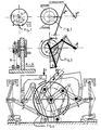
- Figur 1 Scheibe mit der Masse m im Mittelpunkt gelagert, kein Kraftangriff, Drehung = 0.
- Figur 2 Drehscheibe und gelenkig gelagerte steife Stäbe. Die gezeichnete Lage der Stäbe bedeutet Drehbereitschaft für die Scheibe.
- Figur 3 Die Scheibe kaum bewegt bedeutet Knicken der Kurbelstange und die Scheibe erfährt eine starke Bewegung von Punkt A zu B, wobei die Gesetze der Physik wirksam sind. Bisher ist eine Dreivierteldrehung geschehen und die Kraft P lageverändert.
- Figur 4 Mit einem Gegenelement, welches in Ruhestellung die volle Kraft P besitzt, wird die Scheibe weiter gedrückt und das rechte Grundelement wieder in die Ausgangsstellung gebracht.
- Um diesen Wechselvorgang zu erhalten, braucht es mehrere Grundelemente und ebensoviele Kraftangriffe. Eine erste vollständige Triebeinheit kann aus den Figuren 3 - 8, wie nach Urmodell, zusammengesetzt. werden.
- Es zeigt: Figur 3 Ansicht eines Grundelementes
- Figur 4 Geometrie, Drehpunkte u. Kraftangriffe
- Figur 5 Knickelement
- Figur 6 Eventuell mehrteiliges Knickelement
- Figur ? Vollständig dichter Pressluftkolben
- Figur 8 Membranen anstatt Kolben
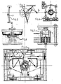
- Figur 9 Ansicht der ersten Triebeinheit.
- Es müssen mindestens zwei Triebeinheiten nach Figur 9 hintereinander auf einer gemeinsamen Welle gekoppelt sein.
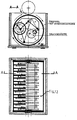
- Die Anzahl gekoppelter Triebeinheiten und die Grösse, sowie Uebersetzungsverhältnisse können gewählt werden. Die Figuren 11 - 16 zeigen verbesserte Modelle, welche im Laufe der Zeit nach Wahl auch ausgeführt werden sollen.
Claims (6)
Priority Applications (3)
| Application Number | Priority Date | Filing Date | Title |
|---|---|---|---|
| DE8181105014T DE3176624D1 (en) | 1981-06-29 | 1981-06-29 | Force transmission system consisting of lever rods and a crank wheel |
| AT81105014T ATE32121T1 (de) | 1981-06-29 | 1981-06-29 | Kraftuebertragungssystem mit hebelgestaengen und kurbelscheibe. |
| EP81105014A EP0068039B1 (de) | 1981-06-29 | 1981-06-29 | Kraftübertragungssystem mit Hebelgestängen und Kurbelscheibe |
Applications Claiming Priority (1)
| Application Number | Priority Date | Filing Date | Title |
|---|---|---|---|
| EP81105014A EP0068039B1 (de) | 1981-06-29 | 1981-06-29 | Kraftübertragungssystem mit Hebelgestängen und Kurbelscheibe |
Publications (2)
| Publication Number | Publication Date |
|---|---|
| EP0068039A1 true EP0068039A1 (de) | 1983-01-05 |
| EP0068039B1 EP0068039B1 (de) | 1988-01-20 |
Family
ID=8187792
Family Applications (1)
| Application Number | Title | Priority Date | Filing Date |
|---|---|---|---|
| EP81105014A Expired EP0068039B1 (de) | 1981-06-29 | 1981-06-29 | Kraftübertragungssystem mit Hebelgestängen und Kurbelscheibe |
Country Status (3)
| Country | Link |
|---|---|
| EP (1) | EP0068039B1 (de) |
| AT (1) | ATE32121T1 (de) |
| DE (1) | DE3176624D1 (de) |
Citations (4)
| Publication number | Priority date | Publication date | Assignee | Title |
|---|---|---|---|---|
| DE456717C (de) * | 1924-10-14 | 1928-02-29 | Russell J Reaney | Kraftuebertragungsgetriebe fuer Umformung einer Drehbewegung in eine hin und her gehende Bewegung |
| US2571153A (en) * | 1947-09-02 | 1951-10-16 | Moore Inc | Apparatus for converting reciprocating motion to rotary motion |
| DE1650689A1 (de) * | 1968-01-19 | 1970-01-29 | Olympia Buerosysteme Gmbh | Intermittierender Antrieb,insbesondere fuer den Transport von Aufzeichnungstraegern |
| US3693463A (en) * | 1970-08-03 | 1972-09-26 | Wilbur G Garman | Linkage for a reciprocating engine crankshaft |
-
1981
- 1981-06-29 EP EP81105014A patent/EP0068039B1/de not_active Expired
- 1981-06-29 AT AT81105014T patent/ATE32121T1/de not_active IP Right Cessation
- 1981-06-29 DE DE8181105014T patent/DE3176624D1/de not_active Expired
Patent Citations (4)
| Publication number | Priority date | Publication date | Assignee | Title |
|---|---|---|---|---|
| DE456717C (de) * | 1924-10-14 | 1928-02-29 | Russell J Reaney | Kraftuebertragungsgetriebe fuer Umformung einer Drehbewegung in eine hin und her gehende Bewegung |
| US2571153A (en) * | 1947-09-02 | 1951-10-16 | Moore Inc | Apparatus for converting reciprocating motion to rotary motion |
| DE1650689A1 (de) * | 1968-01-19 | 1970-01-29 | Olympia Buerosysteme Gmbh | Intermittierender Antrieb,insbesondere fuer den Transport von Aufzeichnungstraegern |
| US3693463A (en) * | 1970-08-03 | 1972-09-26 | Wilbur G Garman | Linkage for a reciprocating engine crankshaft |
Non-Patent Citations (2)
| Title |
|---|
| F.D. JONES: "Ingenious Mechanisms for Designers and Inventors", Band 1, 1930, The Industrial Press, seiten 289-292 New York, U.S.A. * seite 289, unten - seite 292, mitte * * |
| HORTON: "Ingenious Mechanisms for Designers and Inventors", Band III, 1951, The Industrial Press, seiten 233-234, 271-273 New York, U.S.A. * seite 233, mitte - seite 234, mitte; seite 271, mitte - seite 273, mitte * * |
Also Published As
| Publication number | Publication date |
|---|---|
| DE3176624D1 (en) | 1988-02-25 |
| EP0068039B1 (de) | 1988-01-20 |
| ATE32121T1 (de) | 1988-02-15 |
Similar Documents
| Publication | Publication Date | Title |
|---|---|---|
| US4339920A (en) | Method and apparatus utilizing the weight of moving traffic to produce useful work | |
| US3925986A (en) | Air engine | |
| DE2919653A1 (de) | Vorrichtung zur energiegewinnung | |
| US4115034A (en) | Vehicle-actuated air compressor and system therefor | |
| EP3049667A1 (de) | Verfahren und anlage für die kombinierte pumpwasserdruck-druckluft-energiespeicherung mit konstantem turbinen-wasserdruck | |
| WO1985004452A1 (fr) | Moteur hydraulique hydropneumatique | |
| US2848189A (en) | Apparatus for producing power from water waves | |
| DE2507330C3 (de) | Verfahren und Vorrichtung zur Umwandlung der Energie der Meereswellenbewegung in Nutzenergie | |
| WO1981003050A1 (fr) | Procede et installation pour la recuperation de l'energie d'un flot de vehicules automobiles | |
| DE2646131A1 (de) | Antriebsvorrichtung | |
| DE102015217313A1 (de) | Vorrichtung und Verfahren zur Erzeugung von Druckpulsen mit hoher Frequenz und hohem Schubvolumen sowie Verwendung der Vorrichtung zur Druckwechselfestigkeitsprüfung | |
| DE3242773A1 (de) | Mit hilfe von temperaturunterschieden arbeitende kraftmaschine | |
| EP3949089B1 (de) | Anlage zum erzeugen elektrischer energie | |
| DE3331404A1 (de) | Freikolbenmotor zur drehmomenterzeugung | |
| DE102004037923A1 (de) | Verfahren und Einrichtung zur Energieumwandlung | |
| JPH05502713A (ja) | 倍力器 | |
| US2265771A (en) | Hydraulic press | |
| DE3223177A1 (de) | Verfahren und vorrichtung zur ausnutzung von windenergie | |
| CH386854A (de) | Elektrohydraulisches Aggregat zur Erzeugung linearer Kraftbewegungen | |
| DE1287424B (de) | Schwingmuehle | |
| DE801310C (de) | Vorrichtung zum stufenlos regelbaren Anwerfen, insbesondere von Turbinen | |
| US1315527A (en) | Powkr plane | |
| DE111609C (de) | ||
| DE2102957A1 (de) | Pumpe | |
| DE920979C (de) | Vorrichtung zur Erzeugung von Druckluft oder Druckwasser mittels Wasserkraft |
Legal Events
| Date | Code | Title | Description |
|---|---|---|---|
| PUAI | Public reference made under article 153(3) epc to a published international application that has entered the european phase |
Free format text: ORIGINAL CODE: 0009012 |
|
| AK | Designated contracting states |
Designated state(s): AT BE CH DE FR GB IT LI NL SE |
|
| 17P | Request for examination filed |
Effective date: 19830615 |
|
| RAP1 | Party data changed (applicant data changed or rights of an application transferred) |
Owner name: KOHL, FRANZ |
|
| GRAA | (expected) grant |
Free format text: ORIGINAL CODE: 0009210 |
|
| ITF | It: translation for a ep patent filed | ||
| AK | Designated contracting states |
Kind code of ref document: B1 Designated state(s): AT BE CH DE FR GB IT LI NL SE |
|
| REF | Corresponds to: |
Ref document number: 32121 Country of ref document: AT Date of ref document: 19880215 Kind code of ref document: T |
|
| REF | Corresponds to: |
Ref document number: 3176624 Country of ref document: DE Date of ref document: 19880225 |
|
| ET | Fr: translation filed | ||
| GBT | Gb: translation of ep patent filed (gb section 77(6)(a)/1977) | ||
| PLBE | No opposition filed within time limit |
Free format text: ORIGINAL CODE: 0009261 |
|
| STAA | Information on the status of an ep patent application or granted ep patent |
Free format text: STATUS: NO OPPOSITION FILED WITHIN TIME LIMIT |
|
| 26N | No opposition filed | ||
| ITTA | It: last paid annual fee | ||
| EAL | Se: european patent in force in sweden |
Ref document number: 81105014.5 |
|
| PGFP | Annual fee paid to national office [announced via postgrant information from national office to epo] |
Ref country code: FR Payment date: 19960610 Year of fee payment: 16 |
|
| PGFP | Annual fee paid to national office [announced via postgrant information from national office to epo] |
Ref country code: SE Payment date: 19960614 Year of fee payment: 16 Ref country code: AT Payment date: 19960614 Year of fee payment: 16 |
|
| PGFP | Annual fee paid to national office [announced via postgrant information from national office to epo] |
Ref country code: GB Payment date: 19960618 Year of fee payment: 16 |
|
| PGFP | Annual fee paid to national office [announced via postgrant information from national office to epo] |
Ref country code: NL Payment date: 19960620 Year of fee payment: 16 |
|
| PGFP | Annual fee paid to national office [announced via postgrant information from national office to epo] |
Ref country code: BE Payment date: 19960624 Year of fee payment: 16 |
|
| PGFP | Annual fee paid to national office [announced via postgrant information from national office to epo] |
Ref country code: DE Payment date: 19960626 Year of fee payment: 16 |
|
| PG25 | Lapsed in a contracting state [announced via postgrant information from national office to epo] |
Ref country code: GB Free format text: LAPSE BECAUSE OF NON-PAYMENT OF DUE FEES Effective date: 19970629 Ref country code: AT Effective date: 19970629 |
|
| PG25 | Lapsed in a contracting state [announced via postgrant information from national office to epo] |
Ref country code: SE Effective date: 19970630 Ref country code: BE Effective date: 19970630 |
|
| BERE | Be: lapsed |
Owner name: KOHL FRANZ Effective date: 19970630 |
|
| PG25 | Lapsed in a contracting state [announced via postgrant information from national office to epo] |
Ref country code: NL Effective date: 19980101 |
|
| REG | Reference to a national code |
Ref country code: CH Ref legal event code: PL |
|
| GBPC | Gb: european patent ceased through non-payment of renewal fee |
Effective date: 19970629 |
|
| PG25 | Lapsed in a contracting state [announced via postgrant information from national office to epo] |
Ref country code: FR Free format text: LAPSE BECAUSE OF NON-PAYMENT OF DUE FEES Effective date: 19980227 |
|
| EUG | Se: european patent has lapsed |
Ref document number: 81105014.5 |
|
| NLV4 | Nl: lapsed or anulled due to non-payment of the annual fee |
Effective date: 19980101 |
|
| PG25 | Lapsed in a contracting state [announced via postgrant information from national office to epo] |
Ref country code: DE Free format text: LAPSE BECAUSE OF NON-PAYMENT OF DUE FEES Effective date: 19980303 |
|
| REG | Reference to a national code |
Ref country code: CH Ref legal event code: AEN Free format text: DAS PATENT IST AUFGRUND DES WEITERBEHANDLUNGSANTRAGS VOM 05.02.1998 REAKTIVIERT WORDEN. |
|
| REG | Reference to a national code |
Ref country code: FR Ref legal event code: ST |
|
| REG | Reference to a national code |
Ref country code: FR Ref legal event code: ST |
|
| PGFP | Annual fee paid to national office [announced via postgrant information from national office to epo] |
Ref country code: CH Payment date: 19981130 Year of fee payment: 18 |
|
| PG25 | Lapsed in a contracting state [announced via postgrant information from national office to epo] |
Ref country code: LI Free format text: LAPSE BECAUSE OF NON-PAYMENT OF DUE FEES Effective date: 19990630 Ref country code: CH Free format text: LAPSE BECAUSE OF NON-PAYMENT OF DUE FEES Effective date: 19990630 |
|
| REG | Reference to a national code |
Ref country code: CH Ref legal event code: PL |