EP0068039B1 - Dispositif de transmission de force au moyen de leviers et d'un disque à manivelle - Google Patents
Dispositif de transmission de force au moyen de leviers et d'un disque à manivelle Download PDFInfo
- Publication number
- EP0068039B1 EP0068039B1 EP81105014A EP81105014A EP0068039B1 EP 0068039 B1 EP0068039 B1 EP 0068039B1 EP 81105014 A EP81105014 A EP 81105014A EP 81105014 A EP81105014 A EP 81105014A EP 0068039 B1 EP0068039 B1 EP 0068039B1
- Authority
- EP
- European Patent Office
- Prior art keywords
- rod
- lever
- force transmission
- transmission system
- crank wheel
- Prior art date
- Legal status (The legal status is an assumption and is not a legal conclusion. Google has not performed a legal analysis and makes no representation as to the accuracy of the status listed.)
- Expired
Links
Images


Classifications
-
- F—MECHANICAL ENGINEERING; LIGHTING; HEATING; WEAPONS; BLASTING
- F16—ENGINEERING ELEMENTS AND UNITS; GENERAL MEASURES FOR PRODUCING AND MAINTAINING EFFECTIVE FUNCTIONING OF MACHINES OR INSTALLATIONS; THERMAL INSULATION IN GENERAL
- F16H—GEARING
- F16H21/00—Gearings comprising primarily only links or levers, with or without slides
- F16H21/10—Gearings comprising primarily only links or levers, with or without slides all movement being in, or parallel to, a single plane
- F16H21/16—Gearings comprising primarily only links or levers, with or without slides all movement being in, or parallel to, a single plane for interconverting rotary motion and reciprocating motion
- F16H21/18—Crank gearings; Eccentric gearings
- F16H21/22—Crank gearings; Eccentric gearings with one connecting-rod and one guided slide to each crank or eccentric
- F16H21/26—Crank gearings; Eccentric gearings with one connecting-rod and one guided slide to each crank or eccentric with toggle action
-
- F—MECHANICAL ENGINEERING; LIGHTING; HEATING; WEAPONS; BLASTING
- F03—MACHINES OR ENGINES FOR LIQUIDS; WIND, SPRING, OR WEIGHT MOTORS; PRODUCING MECHANICAL POWER OR A REACTIVE PROPULSIVE THRUST, NOT OTHERWISE PROVIDED FOR
- F03G—SPRING, WEIGHT, INERTIA OR LIKE MOTORS; MECHANICAL-POWER PRODUCING DEVICES OR MECHANISMS, NOT OTHERWISE PROVIDED FOR OR USING ENERGY SOURCES NOT OTHERWISE PROVIDED FOR
- F03G7/00—Mechanical-power-producing mechanisms, not otherwise provided for or using energy sources not otherwise provided for
- F03G7/10—Alleged perpetua mobilia
Definitions
- the invention relates to a dynamic transmission according to the preamble of claim 1.
- Dynamic gearboxes with a crank disc and lever linkage are required for various purposes such as short-term energy supply or bridging a short-term high energy requirement.
- a stone crusher is known, which is described in the book “Mechanism, Linkages and Mechanical Controls” by N. P. Chironis, 1965 McGraw-Hiil Verlag, on page 154 in FIG. 6.
- the stone crusher consists of a driven crank disk on which a one-armed lever arm for breaking stones is attached above a crank mechanism and knee joint. The power flow is always directed from the crank disc to the stone-breaking lever arm.
- the object of the invention is to create a dynamic transmission which, with the aid of an energy store, alternately permits a flow of force in one direction to the crank disk and in the other direction to the energy store.
- FIG. 1 shows the basic element of the invention, which can be combined to form further exemplary embodiments.
- the basic element contains several connecting rods 6, 7, 10, a lever 14, which are arranged in a certain way between the fixed points 1, 2 and a crank disk 12.
- the connecting rods 6, 7, 10 are connected to one another in the joint 3.
- the other sides of the connecting rods are articulated on the fixed point 1, the crank pin 11 of the crank disk 12 rotating about its axis 13 and on the lever 14, which can pivot about the other fixed point 2.
- the lever 14 has two lever parts 8, 9 of unequal length.
- the end 4 of one lever piece 8 is articulated on the connecting rod 7.
- This and the other connecting rods 6, 10 are designed as two knee joints, which are arranged with respect to one another in such a way that they pass at the transition support the energy flow per revolution of the crank disk 12 typical for the knee joints in the extended position into the kinked position or vice versa.
- the energy store 15 is arranged in FIG. 1 below the end 5 of the lever part 9. It can also be provided vertically above the end 5, as shown in FIG. 3.
- the following can be considered as energy stores: tension and / or compression springs, compressed air pistons, pneumatic membranes, weights, hydraulic storage means, fluid pressure or buoyancy forces. From this wealth of technical designs, two examples are explained in more detail with reference to FIGS. 9 and 10.
- FIG. 2 shows a partially sectioned illustration of a first exemplary embodiment with two basic elements from FIG. 1.
- the crank disks 12 of the two basic elements are fastened on an axis of rotation 13.
- One of the two crank disks serves as an output. Because of the better overview, only one basic element is completely drawn.
- the energy storage 15, the lever 14, fixed points 2 are not shown.
- the two crank drives 11 are arranged offset by 180 ° on the circumference of the crank disk 12. It is easily possible to combine the arrangement of the so-called twin crank disk of FIG. 2 in a larger number side by side.
- Each twin crank disk is connected to the neighboring twin crank disk via the corresponding crank pin 11, the crank pin being offset in the manner of a crankshaft in the internal combustion engine in the manner of a twin crank disk.
- FIG. 3 as a second embodiment shows the arrangement of two basic elements on one side of the crank disc 12.
- the two basic elements arranged on one side of the crank disk 12 are connected in an articulated manner with a single crank pin 11.
- the front crank pin 11 is offset by about 180 ° on the circumference of the crank disk 12 from the rear.
- Each of the two basic elements arranged on one side of the crank disk works together with an energy store 15, so that four energy stores are provided for the two crank disks.
- Each energy store 15 is connected via a lever linkage 16, 18 to the lever part 9 of the lever 14, which lever linkage is mounted at the fixed point 2 in such a way that the distance a for each basic element is offset or offset. increases.
- the mode of operation of the energy stores and the changes in the distances a are staggered in time.
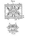
- FIG. 4 shows the third embodiment of the invention, which consists of four basic elements working on a common output
- each basic element of FIG. 4 has two crank disks 12, as the sectional illustration of FIG. 5 shows along the section lines AA.
- the eight crank disks 12 work together, with only a part of the eight shafts 13 representing the common output.
- the basic elements with their connecting rods 6, 7, 10, levers 14 are arranged in a double housing 18.
- Each basic element has its energy store 15, which acts on the end 5 of the lever 14.
- the energy storage device is designed as a bellows made of rubber-elastic material that is compressed and expanded. The bellows are surrounded by a gaseous or liquid medium 20 which exerts a pressure on them.
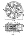
- FIG. 6 shows the fourth embodiment of the invention with eight basic elements, the eight crank disks 12 of which work on a common output 19.
- the reference numbers are the same as in the previous embodiments.
- FIG. 7 is the sectional view of the fourth embodiment and is intended to show the transmission of the energy flow between the crank disk 12 and the common output 19 in a round double housing 18 which, as is known, can absorb larger forces of the gaseous or liquid medium 20.
- the energy stores 15 are bellows trained and are under pressure of the gaseous or liquid medium 20th
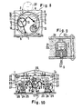
- FIG. 8 shows a section through the fifth embodiment of the invention, which consists of an arrangement of several basic elements one behind the other within a drum 31.
- the crank disk 12 of each basic element has an outer toothing on its circumference and works on the inner toothing of the drum 31.
- the accumulator 15, which engages the end 5 of the lever 14, consists of a pressure vessel, which can be filled with a gaseous or liquid medium.
- the crank pins 11 of each crank disk 12 are offset from one another in a certain manner, as is customary in internal combustion engines with the crankshaft.
- FIG. 9 shows an embodiment of the energy store 15 in the form of a compressed air piston 21 which is movably guided in a cylinder 22.
- the pressure piston arranged in a housing 23 is moved downward in the direction of the arrow by the compressed air 24 and influences the lever 14 of a basic element. Since the compressed air 24 is under high pressure, the compressed air piston 21 has a lamellar seal.
- FIG. 10 shows another exemplary embodiment of the energy store 15, which consists of a piston 25 which is movable in a cylinder 26 by a gaseous or liquid medium 24 under pressure.
- the piston 25 is connected via a cable 27 with a deflection roller 28 to the end 5 of the lever 14 of a basic element of FIG. 1.
- the pressure of the medium 24 can be changed by means of an adjusting device 29, 30, which adjusting device moves the levers 30 in one direction or the other in order to increase or decrease the pressure. This can be done either manually and / or hydraulically, which is shown symbolically in FIG.
- FIG. 11 shows a simplified construction of the second embodiment of FIG. 3.
- the two basic elements, which are arranged on each side of the crank disk 12, are articulated at a single fixed point 1 via common connecting rods 6, 10.
- Each basic element is still articulated at its other fixed point 2.
- the mode of operation of the basic elements articulated on each crank disk 12 is the same as was described in connection with FIG. 3.
- the energy stores 15 are articulated in FIG. 11 below the lever part 9 directly at the end 5.
- FIG. 11 is also intended to show that the individual embodiments of FIGS. 2 to 8 have been structurally changed and the various energy stores, e.g. of Figures 9 and 10, can be used.
Landscapes
- Engineering & Computer Science (AREA)
- General Engineering & Computer Science (AREA)
- Chemical & Material Sciences (AREA)
- Combustion & Propulsion (AREA)
- Mechanical Engineering (AREA)
- Transmission Devices (AREA)
- Reciprocating Pumps (AREA)
Claims (8)
Priority Applications (3)
| Application Number | Priority Date | Filing Date | Title |
|---|---|---|---|
| DE8181105014T DE3176624D1 (en) | 1981-06-29 | 1981-06-29 | Force transmission system consisting of lever rods and a crank wheel |
| AT81105014T ATE32121T1 (de) | 1981-06-29 | 1981-06-29 | Kraftuebertragungssystem mit hebelgestaengen und kurbelscheibe. |
| EP81105014A EP0068039B1 (fr) | 1981-06-29 | 1981-06-29 | Dispositif de transmission de force au moyen de leviers et d'un disque à manivelle |
Applications Claiming Priority (1)
| Application Number | Priority Date | Filing Date | Title |
|---|---|---|---|
| EP81105014A EP0068039B1 (fr) | 1981-06-29 | 1981-06-29 | Dispositif de transmission de force au moyen de leviers et d'un disque à manivelle |
Publications (2)
| Publication Number | Publication Date |
|---|---|
| EP0068039A1 EP0068039A1 (fr) | 1983-01-05 |
| EP0068039B1 true EP0068039B1 (fr) | 1988-01-20 |
Family
ID=8187792
Family Applications (1)
| Application Number | Title | Priority Date | Filing Date |
|---|---|---|---|
| EP81105014A Expired EP0068039B1 (fr) | 1981-06-29 | 1981-06-29 | Dispositif de transmission de force au moyen de leviers et d'un disque à manivelle |
Country Status (3)
| Country | Link |
|---|---|
| EP (1) | EP0068039B1 (fr) |
| AT (1) | ATE32121T1 (fr) |
| DE (1) | DE3176624D1 (fr) |
Family Cites Families (4)
| Publication number | Priority date | Publication date | Assignee | Title |
|---|---|---|---|---|
| DE456717C (de) * | 1924-10-14 | 1928-02-29 | Russell J Reaney | Kraftuebertragungsgetriebe fuer Umformung einer Drehbewegung in eine hin und her gehende Bewegung |
| US2571153A (en) * | 1947-09-02 | 1951-10-16 | Moore Inc | Apparatus for converting reciprocating motion to rotary motion |
| DE1650689A1 (de) * | 1968-01-19 | 1970-01-29 | Olympia Buerosysteme Gmbh | Intermittierender Antrieb,insbesondere fuer den Transport von Aufzeichnungstraegern |
| US3693463A (en) * | 1970-08-03 | 1972-09-26 | Wilbur G Garman | Linkage for a reciprocating engine crankshaft |
-
1981
- 1981-06-29 EP EP81105014A patent/EP0068039B1/fr not_active Expired
- 1981-06-29 AT AT81105014T patent/ATE32121T1/de not_active IP Right Cessation
- 1981-06-29 DE DE8181105014T patent/DE3176624D1/de not_active Expired
Non-Patent Citations (1)
| Title |
|---|
| NICHOLAS P. CHIRONIS; Mechanism, Linkages and Mechanical Controls, 1965 McGraw - Hill Book Company, New York, Seite 154, Figur 6. * |
Also Published As
| Publication number | Publication date |
|---|---|
| DE3176624D1 (en) | 1988-02-25 |
| ATE32121T1 (de) | 1988-02-15 |
| EP0068039A1 (fr) | 1983-01-05 |
Similar Documents
| Publication | Publication Date | Title |
|---|---|---|
| DE2909204C2 (de) | Schwingungserreger mit zwei Unwuchten | |
| DE2404352A1 (de) | Kupplung mit hydraulischer schaltung | |
| DE102009024308A1 (de) | Antriebsanordnung für einen länglichen Schwingkörper | |
| DD155312A5 (de) | Vorrichtung zur beeinflussung des knickwinkels fuer gelenkzuege | |
| DE102007033008A1 (de) | Hydrostatisches Getriebe mit zwei Axialkolbentriebwerken | |
| DE2234410C3 (de) | Querkupplungssystem für Schienenfahrzeuge mit mehrachsigen Drehgestellen | |
| DE2508861C2 (de) | Hydraulische Antriebsvorrichtung mit einem Mitnehmerelemente aufweisenden Antriebskranz | |
| DE3340733A1 (de) | Kolbenverdichter | |
| DE3402100A1 (de) | Schwingungsisolierende lageranordnung fuer ein fahrzeug-antriebsaggregat | |
| DE613838C (de) | Fluessigkeitsgetriebe nach Art der Foettinger-Leitradtransformatoren, bei dem jede Turbindenschaufel oder jede Leitradschaufel oder jede Schaufel beider Raeder in eine Grndschaufel und eine oder mehrere Vorschaufeln eingeteilt ist | |
| DE2528774A1 (de) | Kupplung | |
| DE69204935T2 (de) | Verbund-Wechselgetriebe. | |
| DE4142352A1 (de) | Vorrichtung zum auswechseln von werkzeugsaetzen bei kunststoff-pulverpressen | |
| DE3215795C2 (de) | Druckmittelbeaufschlagbarer Arbeitszylinder | |
| DE2407925C2 (de) | Steuervorrichtung für eine Kraftübertragungseinrichtung an einem landwirtschaftlichen Schlepper | |
| DE3430514C1 (de) | Antriebsvorrichtung zur Umwandlung einer Rotationsbewegung in eine Oszillationsbewegung | |
| DE69108931T2 (de) | Steuereinrichtung für ein toroidal-reibradgetriebe. | |
| DE2831142A1 (de) | Durchbiegungseinstellwalze | |
| DE3328564A1 (de) | Pneumatischer zylindertrieb | |
| DE4026959A1 (de) | Elektromotorisch angetriebene lineareinheit mit hydraulischem druckuebersetzer | |
| DE656270C (de) | Leistungsschalter mit mehreren gemeinsam zu bewegenden Schaltbruecken | |
| DE2717468C3 (de) | Druckmittelbetriebener Stellmotor | |
| DE1628143B2 (de) | Lagerung für Motorkompressoraggregat | |
| EP1952116A1 (fr) | Dispositif de controle pour vehicules destine a mettre en evidence un jeu d'essieu ou un jeu dans les joints de transmission eventuel | |
| DE2928642C2 (de) | Hydraulische oder pneumatische Schwenkkolben-Kraftmaschine |
Legal Events
| Date | Code | Title | Description |
|---|---|---|---|
| PUAI | Public reference made under article 153(3) epc to a published international application that has entered the european phase |
Free format text: ORIGINAL CODE: 0009012 |
|
| AK | Designated contracting states |
Designated state(s): AT BE CH DE FR GB IT LI NL SE |
|
| 17P | Request for examination filed |
Effective date: 19830615 |
|
| RAP1 | Party data changed (applicant data changed or rights of an application transferred) |
Owner name: KOHL, FRANZ |
|
| GRAA | (expected) grant |
Free format text: ORIGINAL CODE: 0009210 |
|
| ITF | It: translation for a ep patent filed | ||
| AK | Designated contracting states |
Kind code of ref document: B1 Designated state(s): AT BE CH DE FR GB IT LI NL SE |
|
| REF | Corresponds to: |
Ref document number: 32121 Country of ref document: AT Date of ref document: 19880215 Kind code of ref document: T |
|
| REF | Corresponds to: |
Ref document number: 3176624 Country of ref document: DE Date of ref document: 19880225 |
|
| ET | Fr: translation filed | ||
| GBT | Gb: translation of ep patent filed (gb section 77(6)(a)/1977) | ||
| PLBE | No opposition filed within time limit |
Free format text: ORIGINAL CODE: 0009261 |
|
| STAA | Information on the status of an ep patent application or granted ep patent |
Free format text: STATUS: NO OPPOSITION FILED WITHIN TIME LIMIT |
|
| 26N | No opposition filed | ||
| ITTA | It: last paid annual fee | ||
| EAL | Se: european patent in force in sweden |
Ref document number: 81105014.5 |
|
| PGFP | Annual fee paid to national office [announced via postgrant information from national office to epo] |
Ref country code: FR Payment date: 19960610 Year of fee payment: 16 |
|
| PGFP | Annual fee paid to national office [announced via postgrant information from national office to epo] |
Ref country code: SE Payment date: 19960614 Year of fee payment: 16 Ref country code: AT Payment date: 19960614 Year of fee payment: 16 |
|
| PGFP | Annual fee paid to national office [announced via postgrant information from national office to epo] |
Ref country code: GB Payment date: 19960618 Year of fee payment: 16 |
|
| PGFP | Annual fee paid to national office [announced via postgrant information from national office to epo] |
Ref country code: NL Payment date: 19960620 Year of fee payment: 16 |
|
| PGFP | Annual fee paid to national office [announced via postgrant information from national office to epo] |
Ref country code: BE Payment date: 19960624 Year of fee payment: 16 |
|
| PGFP | Annual fee paid to national office [announced via postgrant information from national office to epo] |
Ref country code: DE Payment date: 19960626 Year of fee payment: 16 |
|
| PG25 | Lapsed in a contracting state [announced via postgrant information from national office to epo] |
Ref country code: GB Free format text: LAPSE BECAUSE OF NON-PAYMENT OF DUE FEES Effective date: 19970629 Ref country code: AT Effective date: 19970629 |
|
| PG25 | Lapsed in a contracting state [announced via postgrant information from national office to epo] |
Ref country code: SE Effective date: 19970630 Ref country code: BE Effective date: 19970630 |
|
| BERE | Be: lapsed |
Owner name: KOHL FRANZ Effective date: 19970630 |
|
| PG25 | Lapsed in a contracting state [announced via postgrant information from national office to epo] |
Ref country code: NL Effective date: 19980101 |
|
| REG | Reference to a national code |
Ref country code: CH Ref legal event code: PL |
|
| GBPC | Gb: european patent ceased through non-payment of renewal fee |
Effective date: 19970629 |
|
| PG25 | Lapsed in a contracting state [announced via postgrant information from national office to epo] |
Ref country code: FR Free format text: LAPSE BECAUSE OF NON-PAYMENT OF DUE FEES Effective date: 19980227 |
|
| EUG | Se: european patent has lapsed |
Ref document number: 81105014.5 |
|
| NLV4 | Nl: lapsed or anulled due to non-payment of the annual fee |
Effective date: 19980101 |
|
| PG25 | Lapsed in a contracting state [announced via postgrant information from national office to epo] |
Ref country code: DE Free format text: LAPSE BECAUSE OF NON-PAYMENT OF DUE FEES Effective date: 19980303 |
|
| REG | Reference to a national code |
Ref country code: CH Ref legal event code: AEN Free format text: DAS PATENT IST AUFGRUND DES WEITERBEHANDLUNGSANTRAGS VOM 05.02.1998 REAKTIVIERT WORDEN. |
|
| REG | Reference to a national code |
Ref country code: FR Ref legal event code: ST |
|
| REG | Reference to a national code |
Ref country code: FR Ref legal event code: ST |
|
| PGFP | Annual fee paid to national office [announced via postgrant information from national office to epo] |
Ref country code: CH Payment date: 19981130 Year of fee payment: 18 |
|
| PG25 | Lapsed in a contracting state [announced via postgrant information from national office to epo] |
Ref country code: LI Free format text: LAPSE BECAUSE OF NON-PAYMENT OF DUE FEES Effective date: 19990630 Ref country code: CH Free format text: LAPSE BECAUSE OF NON-PAYMENT OF DUE FEES Effective date: 19990630 |
|
| REG | Reference to a national code |
Ref country code: CH Ref legal event code: PL |