EP0068115A2 - Strömungs-Teilvorrichtung zum Aufspalten eines Stromes pulverförmigen Materials in mehrere Teilströme - Google Patents
Strömungs-Teilvorrichtung zum Aufspalten eines Stromes pulverförmigen Materials in mehrere Teilströme Download PDFInfo
- Publication number
- EP0068115A2 EP0068115A2 EP82103975A EP82103975A EP0068115A2 EP 0068115 A2 EP0068115 A2 EP 0068115A2 EP 82103975 A EP82103975 A EP 82103975A EP 82103975 A EP82103975 A EP 82103975A EP 0068115 A2 EP0068115 A2 EP 0068115A2
- Authority
- EP
- European Patent Office
- Prior art keywords
- flow
- stream
- splitter
- outlet
- pulverulent material
- Prior art date
- Legal status (The legal status is an assumption and is not a legal conclusion. Google has not performed a legal analysis and makes no representation as to the accuracy of the status listed.)
- Withdrawn
Links
Images

Classifications
-
- F—MECHANICAL ENGINEERING; LIGHTING; HEATING; WEAPONS; BLASTING
- F23—COMBUSTION APPARATUS; COMBUSTION PROCESSES
- F23K—FEEDING FUEL TO COMBUSTION APPARATUS
- F23K3/00—Feeding or distributing of lump or pulverulent fuel to combustion apparatus
- F23K3/02—Pneumatic feeding arrangements, i.e. by air blast
-
- B—PERFORMING OPERATIONS; TRANSPORTING
- B65—CONVEYING; PACKING; STORING; HANDLING THIN OR FILAMENTARY MATERIAL
- B65G—TRANSPORT OR STORAGE DEVICES, e.g. CONVEYORS FOR LOADING OR TIPPING, SHOP CONVEYOR SYSTEMS OR PNEUMATIC TUBE CONVEYORS
- B65G53/00—Conveying materials in bulk through troughs, pipes or tubes by floating the materials or by flow of gas, liquid or foam
- B65G53/34—Details
- B65G53/52—Adaptations of pipes or tubes
- B65G53/528—Flux combining or dividing arrangements
-
- C—CHEMISTRY; METALLURGY
- C21—METALLURGY OF IRON
- C21B—MANUFACTURE OF IRON OR STEEL
- C21B5/00—Making pig-iron in the blast furnace
- C21B5/001—Injecting additional fuel or reducing agents
- C21B5/003—Injection of pulverulent coal
-
- F—MECHANICAL ENGINEERING; LIGHTING; HEATING; WEAPONS; BLASTING
- F23—COMBUSTION APPARATUS; COMBUSTION PROCESSES
- F23K—FEEDING FUEL TO COMBUSTION APPARATUS
- F23K2203/00—Feeding arrangements
- F23K2203/10—Supply line fittings
- F23K2203/105—Flow splitting devices to feed a plurality of burners
Definitions
- the present invention relates to an apparatus for splitting a stream of pulverulent material into a multiplicity of equal streams for pneumatically transporting from a single source to multiple receiving stations.
- a common type of such a device utilizes a conical body disposed in the flow path of the single stream to perfect the division of the stream into a multiplicity of streams.
- a typical embodiment of such a flow splitter as disclosed in U.S. Patent 1,769,763, comprises a generally elongated, up-right distributor housing having an inlet in the top and a multiplicity of outlets disposed around its bottom periphery.
- a conical body is disposed within the housing with the base of the cone at the outlet end of the housing and the apex of the cone pointed upward toward the top of the housing.
- the conical body may be stationary or it may be rotatable as disclosed in U.S. Patent 1,871,853.
- the pulverulent material is mixed with a transport medium, most commonly air, and passed into the flow splitter in a whirling pattern under pressure supplied by a fan or a compressor.
- a transport medium most commonly air
- the stream passes through the distributor housing of the splitter, it diverges outwardly in a swirling pattern over the surface of the conical body and through the various outlets disposed around the face of the conical-body into the individual transport lines connected to the opposite end of the distributor housing.
- a problem typically encountered with such flow splitters as described above occurs when flow through one or more of the transport lines being fed by the distributor is shut off.
- a damper or a valve disposed in the transport downstream of the flow splitter is closed in order to shut off flow to the transport line.
- pulverulent material can collect and become packed in the transport line between the closed damper or valve and the outlet of the flow splitter to which the line is connected. This blockage of material can cause problems in bringing a transport line back into service as the pulverulent material can become packed to a very high density and act as a block to flow.
- a flow splitter for dividing a single stream of pulverulent material entrained in air to a multiplicity of substantially equal substreams for delivery to a multiplicity of receiving stations.
- the flow splitter comprises an elongated open-ended convergent nozzle for receiving a stream of pulverulent material entrained in air from a supply source, a distributor housing defining a substantially cylindrical distribution chamber having inlet mated to the outlet of the convergent nozzle and a plurality of outlet openings equally spaced about the periphery of an opening from the opposite end thereof, a splitter plug having a conical tip coaxically disposed within the distribution chamber with the tip of the cone facing the inlet to the distribution chamber and the base of the conical tip lying adjacent the outlet opening of the chamber, and a plurality of outlet valve assemblies equal in number to the number of outlet openings.
- Each outlet valve defines a flow conduit having an inlet mated to an outlet opening in the distribution chamber and an outlet connected to a transport pipe through which the substream of pulverulent material leaving the flow splitter therethrough is directed to a receiving station.
- each valve assembly there is disposed within the flow conduit of each valve assembly, a valve member which is slidably movable and selectively positionable therein at locations from the inlet to the flow conduit from the distribution chamber to a point downstream of the outlet of the flow conduit.
- the end face of each valve member is contoured to conform with the inner surface of the cylindrical distribution chamber to which the valve assembly mates so that when the flow conduit is closed off by positioning the valve member at the inlet thereto, the end face of the valve member mates with the inner surface of the cylindrical distribution chamber so as to present a smooth surface to the flow of pulverulent material within a distribution chamber and thereby not generate turbulence which would disturb the uniform distribution of pulverulent material through the remaining open outlet openings in the distribution chamber.
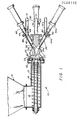
- a pulverulent material distribution apparatus employing the flow splitter 20 of the present invention.
- the pulverulent material distribution apparatus 10 is operative to pneumatically transport pulverulent material from a single source, such as a storage bin, to multiple receiving stations and to equally distribute the pulverulent material amongst the. receiving stations.
- the pulverulent material distribution apparatus 10 is comprised of a solids pump 12, a flow splitter 20, illustrated in the drawing as providing a four way split, and the transport lines 30 which interconnect the flow splitter to the various receiving stations.
- the solids pump 12 is arranged to receive a pulverulent material from a source such as storage bin 14.
- a rotary feed screw 16 is concentrically and rotatably mounted within the solids pump 12.
- a drive motor not shown, rotates the screw at a high speed typically on the order of 1250 rpm. Pulverulent material from the storage bin 14 passes into the pump 12 and is engaged in the flights 18 of the screw 16.
- the pulverulent material engaged by the helical flights 18 of the screw passes along the length of the screw to the outlet end of the pump 12 and discharges therefrom into the flow splitter 20, which is comprised of an inlet nozzle 22 defining a receiving/mixing chamber 24, a distributor housing 26 defining a distribution chamber 28 and a plurality of outlet valve assemblies 40.
- an air header 32 Disposed about the outlet end of the solids pump 12 is an air header 32 for supplying air under pressure as the transport medium for the pulverulent material.
- the pulverulent material discharging from the pump 12 and the high pressure air supplied from air header 32 pass into the mixing chamber 24 of the inlet nozzle 22.
- the mixing of the air with the pulverulent material may be promoted by swirling the air flow as it enters the mixing chamber from the supply header 32.
- the resultant vortex formed in the mixing chamber improves the intermixing of the air with the pulverulent material and aids in insuring that a substantially uniform mixture of pulverulent material and air exists at the outlet of the mixing chamber 34.
- the mixing chamber 24 of the inlet nozzle 22 is preferably in the form of an elongated open ended chamber converging from a maximum diameter at its inlet end to a minimum diameter at its outlet end as shown in Figure 1.
- the convergent nature of the mixing chamber 24 further insures that the coal and air entering at the inlet end thereof are thoroughly mixed to provide a substantially uniform mixture of pulverulent material and air at the outlet end of the nozzle 22. Additionally, the convergent nature of the mixing chamber 24 causes the coal and air mixture to accelerate to an essentially uniform velocity at the outlet of the mixing chamber.
- the substantially uniform mixture of pulverulent material and air discharging from the inlet nozzle 22 passes Into a substantially cylindrical distribution chamber 28 defined by the distributor housing 26.
- the distribution chamber 28 has an inlet end which mates to the outlet end of the mixing chamber 24 for receiving the mixture of pulverulent material and air discharging through the inlet nozzle 22 and a plurality of outlet openings 34 equally spaced about the periphery of and opening from the opposite end of the distribution chamber 28.
- the outlet openings 34 may be disposed in the sidewall of the cylindrical distribution chamber 28 as shown in Figure 1, or the outlet openings 34 may be disposed in the floor of the outlet chamber 38 as shown in Figure 2.
- a splitter plug 36 having a conical tip is coaxially disposed within the distribution chamber 28.
- the conical tip of the splitter plug 36 faces the inlet end of the distribution chamber with the base of the conical tip aligned adjacent the outlet openings 34 about the periphery of the distribution chamber 28. Tests have indicated that, although satisfactory distribution can be obtained without the plug 36, the splitter plug 36 when installed enhances performance of flow splitter and aids in uniformly distributing the pulverulent material and air mixture to the various outlet openings.
- each outlet opening 34 Associated with each outlet opening 34 is an outlet valve assembly 40 which defines a flow conduit 42.
- the flow conduit 42 has an inlet end mated to its associated outlet opening 34 in the distributor chamber 28 and an outlet opening to which a transport pipe 30 is attached for directing the pulverulent material and air mixture passing therethrough to the desired receiving station.
- a valve member 44 is slottably disposed within the flow conduit 42 of each valve assembly 40. Each valve member 44 is selectably positionable within the flow conduit 42 from the outlet opening 34 of the distributor housing 26 at the inlet end of the flow conduit to a point downstream of the outlet 48 of the flow conduit 42 to which the transport pipe 30 is connected.
- valve member 44A of valve assembly 40A associated with transport pipe 30A is positioned within the flow conduit through valve assembly 40A so that the end face of valve member 44A is flushed with the outlet opening from the distribution chamber 28.
- the end face 46 of each valve member 44 is contoured to conform with the inner surface of the cylindrical housing 26 defining the distribution chamber 28.
- purge means may be provided to clean the transport line 30A and the flow conduit 42 of any pulverulent material when either bringing the distribution system on line or taking it off line.
- the purge means comprise a nozzle 50 associated with the valve assembly and opening into the flow conduit 42 at a position opposite the outlet opening 48.
- a hole 60 extends transversely through the valve member 44 so as to communicate the purge nozzle 50 with the transport line 30a when the valve member 44 is in the fully extending position, i.e., when the end face 46 of the valve member is positioned at the outlet 34 in the distribution chamber such as illustrated by valve member 44a in the drawing. In this position, pressurized purge air may be directed from purge nozzle 50 through the hole 60 in valve member 44a into transport line 30a to clear the line of any pulverulent material which may have deposited therein when the system was shut down.
Landscapes
- Engineering & Computer Science (AREA)
- Chemical & Material Sciences (AREA)
- Mechanical Engineering (AREA)
- Combustion & Propulsion (AREA)
- General Engineering & Computer Science (AREA)
- Manufacturing & Machinery (AREA)
- Materials Engineering (AREA)
- Metallurgy (AREA)
- Organic Chemistry (AREA)
- Air Transport Of Granular Materials (AREA)
- Devices And Processes Conducted In The Presence Of Fluids And Solid Particles (AREA)
- Nozzles (AREA)
Applications Claiming Priority (2)
| Application Number | Priority Date | Filing Date | Title |
|---|---|---|---|
| US06/278,242 US4413935A (en) | 1981-06-29 | 1981-06-29 | Flow splitter for dividing a stream of pulverulent material into multiple streams |
| US278242 | 1981-06-29 |
Publications (2)
| Publication Number | Publication Date |
|---|---|
| EP0068115A2 true EP0068115A2 (de) | 1983-01-05 |
| EP0068115A3 EP0068115A3 (de) | 1983-08-10 |
Family
ID=23064242
Family Applications (1)
| Application Number | Title | Priority Date | Filing Date |
|---|---|---|---|
| EP82103975A Withdrawn EP0068115A3 (de) | 1981-06-29 | 1982-05-07 | Strömungs-Teilvorrichtung zum Aufspalten eines Stromes pulverförmigen Materials in mehrere Teilströme |
Country Status (8)
| Country | Link |
|---|---|
| US (1) | US4413935A (de) |
| EP (1) | EP0068115A3 (de) |
| JP (1) | JPS586826A (de) |
| AU (1) | AU543852B2 (de) |
| CA (1) | CA1182851A (de) |
| ES (1) | ES266032Y (de) |
| IN (1) | IN156097B (de) |
| ZA (1) | ZA824590B (de) |
Cited By (10)
| Publication number | Priority date | Publication date | Assignee | Title |
|---|---|---|---|---|
| EP0140570A1 (de) * | 1983-09-28 | 1985-05-08 | Macawber Engineering Limited | Zuführen von körnigem Material |
| FR2584480A1 (fr) * | 1985-07-05 | 1987-01-09 | Charbonnages De France | Procede de regulation de la puissance thermique d'un incinerateur d'ordures menageres et installation pour la mise en oeuvre de ce procede |
| EP0211295A1 (de) * | 1985-08-05 | 1987-02-25 | Paul Wurth S.A. | Verfahren und Vorrichtung für ein dosiertes Einblasen auf pneumatischem Weg von feinkörnigen Feststoffen in einem unter wechselndem Druck stehenden Gehäuse |
| EP0526805A1 (de) * | 1991-08-05 | 1993-02-10 | Siemens Aktiengesellschaft | Vorrichtung mit Abzweigungen zur Pulverförderung |
| WO2008046656A1 (de) * | 2006-10-20 | 2008-04-24 | Claudius Peters Technologies Gmbh | Feststoffverteiler für einblasanlagen, hochöfen und dergleichen |
| WO2009003555A1 (de) * | 2007-07-05 | 2009-01-08 | Lincoln Gmbh | Vorrichtung zum aufteilen einer mittels einer gasströmung transportieren flüssigkeit |
| WO2012166117A1 (en) * | 2011-05-31 | 2012-12-06 | Pratt & Whitney Rocketdyne, Inc. | Flow splitter for a compact gasification reactor system |
| WO2011163192A3 (en) * | 2010-06-23 | 2013-06-13 | General Electric Company | Fluidization device for solid fuel particles |
| EP3419434A4 (de) * | 2016-02-26 | 2019-10-23 | Erik Garfinkel | Betonausgabesubsystem für automatisiertes betonfertigungssystem |
| CN115751363A (zh) * | 2022-09-30 | 2023-03-07 | 北京天地融创科技股份有限公司 | 粉体供料系统和锅炉 |
Families Citing this family (27)
| Publication number | Priority date | Publication date | Assignee | Title |
|---|---|---|---|---|
| GB2112506A (en) * | 1981-12-30 | 1983-07-20 | Shell Int Research | Distributing valve |
| DE3239897A1 (de) * | 1982-10-28 | 1984-05-03 | Trützschler GmbH & Co KG, 4050 Mönchengladbach | Verfahren und vorrichtung zur foerderung von faserfoermigen stoffen, insbesondere von in luft schwebend gefoerderten textilen faserflocken bei spinnereivorbereitungsmaschinen |
| FR2548556B1 (fr) * | 1983-07-04 | 1985-10-18 | Saint Gobain Vitrage | Dispositif de distribution de produits pulverulents en suspension dans un gaz |
| US5028009A (en) * | 1989-12-22 | 1991-07-02 | Ag-Chem Equipment Co., Inc. | Distributor head for use with booms having shut-off capability |
| US5246097A (en) * | 1992-10-21 | 1993-09-21 | Simplimatic Engineering Company | Line changing system for air bottle conveyors |
| US5645381A (en) * | 1994-09-13 | 1997-07-08 | Trw Inc. | Variable-split blowdown coal feed system |
| DE4438135A1 (de) * | 1994-10-27 | 1996-05-02 | Zeppelin Schuettguttech Gmbh | Verladevorrichtung für Schüttgüter |
| GB9802527D0 (en) | 1998-02-06 | 1998-04-01 | Flexi Coil Ltd | Delivery of seeds by air conveyor |
| ITTO20030036A1 (it) * | 2003-01-24 | 2004-07-25 | Fiat Ricerche | Sistema di climatizzazione di autoveicolo con dispositivo distributore e miscelatore di aria, ad effetto coanda, avente uscite a temperature differenziate |
| KR102055873B1 (ko) * | 2007-07-09 | 2019-12-13 | 제넨테크, 인크. | 폴리펩티드의 재조합 생산 동안의 디술피드 결합 환원의 방지 |
| US7942162B2 (en) * | 2008-01-14 | 2011-05-17 | National Tank Company | Tee flow splitter |
| DE102008036095B4 (de) * | 2008-08-04 | 2015-04-02 | Schenck Process Gmbh | Brennerzuführung |
| US7798079B2 (en) * | 2008-11-14 | 2010-09-21 | Cnh Canada, Ltd. | Pressure supply assembly for an agricultural implement with dense phase product flow |
| US7806061B2 (en) * | 2008-11-14 | 2010-10-05 | Cnh Canada, Ltd. | Agricultural implement with dense phase product dispensing and purging |
| US8342373B2 (en) * | 2008-11-14 | 2013-01-01 | Cnh Canada, Ltd. | Valve and method for dense phase flow control |
| US7752984B2 (en) * | 2008-11-14 | 2010-07-13 | Cnh Canada, Ltd. | Device and method for dense phase transport of seed |
| US7789103B2 (en) * | 2008-11-14 | 2010-09-07 | Cnh Canada, Ltd. | Dense phase induction system and method |
| US7640877B1 (en) | 2008-11-14 | 2010-01-05 | Cnh Canada, Ltd. | Dense phase distribution branch |
| US7779769B2 (en) * | 2008-11-14 | 2010-08-24 | Cnh Canada, Ltd. | Agricultural implement with dense phase product flow from a primary container |
| US7743719B2 (en) * | 2008-11-14 | 2010-06-29 | Cnh Canada, Ltd. | Sectional distribution of granular product |
| US7798078B2 (en) * | 2008-11-14 | 2010-09-21 | Cnh Canada, Ltd. | Granular containment assembly and method |
| PL216367B1 (pl) * | 2009-05-14 | 2014-03-31 | Int Tobacco Machinery Poland | Sposób i urządzenie do dystrybucji krajanki tytoniowej do zasilania maszyn produkujących papierosy |
| US9719681B2 (en) * | 2011-06-06 | 2017-08-01 | General Electric Company | System and method for supplying fuel |
| US8960275B1 (en) * | 2011-07-29 | 2015-02-24 | Baker Manufacturing Company, LLC | Pitless well adaptor with high-efficiency flow divider |
| US8991506B2 (en) * | 2011-10-31 | 2015-03-31 | Halliburton Energy Services, Inc. | Autonomous fluid control device having a movable valve plate for downhole fluid selection |
| US9242807B2 (en) * | 2011-12-09 | 2016-01-26 | Saeed Bizhanzadeh | Vortex pneumatic conveyance apparatus |
| FI130892B1 (fi) * | 2020-08-20 | 2024-05-10 | Teknologian Tutkimuskeskus Vtt Oy | Syötin ja menetelmä muovia sisältävän raaka-aineen syöttämiseksi |
Family Cites Families (11)
| Publication number | Priority date | Publication date | Assignee | Title |
|---|---|---|---|---|
| USRE24716E (en) | 1959-10-06 | Air flow conveying system | ||
| US1769763A (en) * | 1925-06-16 | 1930-07-01 | Int Comb Eng Corp | Pulverized-fuel-distributing apparatus |
| US1871853A (en) * | 1927-08-09 | 1932-08-16 | Joseph E Kennedy | Pneumatic transporting and distributing of pulverized material |
| US2084397A (en) * | 1936-01-14 | 1937-06-22 | Socony Vacuum Oil Co Inc | Control valve |
| US3255938A (en) * | 1964-08-10 | 1966-06-14 | Gen Equipment Mfg & Sales Inc | Spigot for refrigerated confection |
| US3386474A (en) * | 1965-05-26 | 1968-06-04 | Chemagro Corp | Diverter valve for finely divided solids |
| DE1525608C3 (de) * | 1966-05-20 | 1974-09-26 | Fa. Otto Egelhof, 7012 Fellbach | Mehrstufiger Verteiler für strömende Flüssigkeiten oder Flüssigkeits-Dampf gemische |
| US3508577A (en) * | 1967-04-05 | 1970-04-28 | Pan American Petroleum Corp | Blowout control valve for drilling well |
| JPS557132A (en) * | 1978-06-29 | 1980-01-18 | Babcock Hitachi Kk | Powder carrying method |
| JPS5819568B2 (ja) * | 1979-06-30 | 1983-04-19 | 手塚 善智 | 粉粒状物の連続搬送装置 |
| FI801859A7 (fi) * | 1979-11-19 | 1981-01-01 | Strahman Valves Inc | Männän asennon osoittimella varustettu näytteenottoventtiili. |
-
1981
- 1981-06-29 US US06/278,242 patent/US4413935A/en not_active Expired - Fee Related
-
1982
- 1982-03-22 IN IN319/CAL/82A patent/IN156097B/en unknown
- 1982-04-22 CA CA000401498A patent/CA1182851A/en not_active Expired
- 1982-05-07 EP EP82103975A patent/EP0068115A3/de not_active Withdrawn
- 1982-06-22 ES ES1982266032U patent/ES266032Y/es not_active Expired
- 1982-06-28 AU AU85375/82A patent/AU543852B2/en not_active Ceased
- 1982-06-28 ZA ZA824590A patent/ZA824590B/xx unknown
- 1982-06-29 JP JP57110937A patent/JPS586826A/ja active Granted
Cited By (17)
| Publication number | Priority date | Publication date | Assignee | Title |
|---|---|---|---|---|
| EP0140570A1 (de) * | 1983-09-28 | 1985-05-08 | Macawber Engineering Limited | Zuführen von körnigem Material |
| FR2584480A1 (fr) * | 1985-07-05 | 1987-01-09 | Charbonnages De France | Procede de regulation de la puissance thermique d'un incinerateur d'ordures menageres et installation pour la mise en oeuvre de ce procede |
| EP0213980A3 (en) * | 1985-07-05 | 1988-07-06 | Charbonnages De France, Etablissement Public Dit: | Method of controlling the thermal output of a domestic-refuse incinerator, and installation for carrying out this method |
| EP0211295A1 (de) * | 1985-08-05 | 1987-02-25 | Paul Wurth S.A. | Verfahren und Vorrichtung für ein dosiertes Einblasen auf pneumatischem Weg von feinkörnigen Feststoffen in einem unter wechselndem Druck stehenden Gehäuse |
| EP0526805A1 (de) * | 1991-08-05 | 1993-02-10 | Siemens Aktiengesellschaft | Vorrichtung mit Abzweigungen zur Pulverförderung |
| CN101627275B (zh) * | 2006-10-20 | 2013-01-23 | 克劳迪亚斯·彼得斯工程有限责任公司 | 用于吹入设备、高炉等的固体物料分配器 |
| WO2008046656A1 (de) * | 2006-10-20 | 2008-04-24 | Claudius Peters Technologies Gmbh | Feststoffverteiler für einblasanlagen, hochöfen und dergleichen |
| EA016401B1 (ru) * | 2006-10-20 | 2012-04-30 | Клаудиус Петерс Проджектс Гмбх | Распределитель твердого вещества в установках для вдувания |
| US8348556B2 (en) | 2006-10-20 | 2013-01-08 | Claudius Peters Projects Gmbh | Solids distributor for injection plants, blast furnaces and the like |
| WO2009003555A1 (de) * | 2007-07-05 | 2009-01-08 | Lincoln Gmbh | Vorrichtung zum aufteilen einer mittels einer gasströmung transportieren flüssigkeit |
| CN103328892A (zh) * | 2010-06-23 | 2013-09-25 | 通用电气公司 | 用于固体燃料颗粒的流体化装置 |
| WO2011163192A3 (en) * | 2010-06-23 | 2013-06-13 | General Electric Company | Fluidization device for solid fuel particles |
| CN103328892B (zh) * | 2010-06-23 | 2016-03-23 | 通用电气公司 | 用于固体燃料颗粒的流体化系统 |
| WO2012166117A1 (en) * | 2011-05-31 | 2012-12-06 | Pratt & Whitney Rocketdyne, Inc. | Flow splitter for a compact gasification reactor system |
| US9080115B2 (en) | 2011-05-31 | 2015-07-14 | Aerojet Rocketdyne Of De, Inc. | Flow splitter for a compact gasification reactor system |
| EP3419434A4 (de) * | 2016-02-26 | 2019-10-23 | Erik Garfinkel | Betonausgabesubsystem für automatisiertes betonfertigungssystem |
| CN115751363A (zh) * | 2022-09-30 | 2023-03-07 | 北京天地融创科技股份有限公司 | 粉体供料系统和锅炉 |
Also Published As
| Publication number | Publication date |
|---|---|
| ZA824590B (en) | 1983-04-27 |
| JPS586826A (ja) | 1983-01-14 |
| AU543852B2 (en) | 1985-05-02 |
| IN156097B (de) | 1985-05-11 |
| CA1182851A (en) | 1985-02-19 |
| AU8537582A (en) | 1983-01-06 |
| JPS6127294B2 (de) | 1986-06-25 |
| US4413935A (en) | 1983-11-08 |
| ES266032U (es) | 1983-01-16 |
| EP0068115A3 (de) | 1983-08-10 |
| ES266032Y (es) | 1983-07-16 |
Similar Documents
| Publication | Publication Date | Title |
|---|---|---|
| US4413935A (en) | Flow splitter for dividing a stream of pulverulent material into multiple streams | |
| US4183702A (en) | Storage and extraction device for powdered products | |
| US4019783A (en) | Process and apparatus for continuously conveying particulate material | |
| US5863155A (en) | Boundary air/laminar flow conveying system | |
| JPS58501589A (ja) | 粉粒体分配方法及びその装置 | |
| SU1355118A3 (ru) | Устройство дл пневматической и гидравлической подачи пылевидного,порошкообразного или зернистого сыпучего материала | |
| CA1037521A (en) | Distributor | |
| US4257334A (en) | Apparatus and method for regulating the distribution of granulate | |
| US4491442A (en) | Method and device for pneumatic feeding of materials | |
| US4441822A (en) | Apparatus for mixing and distributing solid particulate material | |
| US4840753A (en) | Device for aerating fluids, in particular during flotation | |
| US4660768A (en) | Nozzle for injecting solids pneumatically | |
| KR20120044888A (ko) | 고체 입자를 공기압으로 반송하기 위한 공급 용기 및 시스템 | |
| US4128343A (en) | Apparatus for blending granular materials | |
| US4486101A (en) | Apparatus for blending particulate materials | |
| US1120535A (en) | Mixer for comminuted material. | |
| US6267540B1 (en) | Device for creating a powder-air-mixture | |
| EP0140570A1 (de) | Zuführen von körnigem Material | |
| CN201239609Y (zh) | 粉料投加器 | |
| GB2095123A (en) | Apparatus for introducing a gas into a liquid or a liquid-solids mixture | |
| US3272561A (en) | Distributor | |
| US4573800A (en) | Blender bulk feed valve | |
| KR20030046456A (ko) | 저유동성 덩어리 재료를 공급 라인으로 도입하는 장치 | |
| US6176276B1 (en) | Granular material feeding device | |
| US2616766A (en) | Material distributing apparatus |
Legal Events
| Date | Code | Title | Description |
|---|---|---|---|
| PUAI | Public reference made under article 153(3) epc to a published international application that has entered the european phase |
Free format text: ORIGINAL CODE: 0009012 |
|
| AK | Designated contracting states |
Designated state(s): FR GB IT NL |
|
| PUAL | Search report despatched |
Free format text: ORIGINAL CODE: 0009013 |
|
| RHK1 | Main classification (correction) |
Ipc: F23K 3/02 |
|
| AK | Designated contracting states |
Designated state(s): FR GB IT NL |
|
| STAA | Information on the status of an ep patent application or granted ep patent |
Free format text: STATUS: THE APPLICATION HAS BEEN WITHDRAWN |
|
| 18W | Application withdrawn |
Withdrawal date: 19840502 |
|
| RIN1 | Information on inventor provided before grant (corrected) |
Inventor name: LEXA, GARY FRANK Inventor name: SMITH, DONALD ARTHUR |