EP0068118A2 - Construction simplifiée d'interrupteur électrique - Google Patents
Construction simplifiée d'interrupteur électrique Download PDFInfo
- Publication number
- EP0068118A2 EP0068118A2 EP82104006A EP82104006A EP0068118A2 EP 0068118 A2 EP0068118 A2 EP 0068118A2 EP 82104006 A EP82104006 A EP 82104006A EP 82104006 A EP82104006 A EP 82104006A EP 0068118 A2 EP0068118 A2 EP 0068118A2
- Authority
- EP
- European Patent Office
- Prior art keywords
- conductive contact
- movable conductive
- terminals
- contact
- cavity
- Prior art date
- Legal status (The legal status is an assumption and is not a legal conclusion. Google has not performed a legal analysis and makes no representation as to the accuracy of the status listed.)
- Granted
Links
- 238000010276 construction Methods 0.000 title description 7
- 230000002093 peripheral effect Effects 0.000 claims description 20
- 229920005989 resin Polymers 0.000 claims description 12
- 239000011347 resin Substances 0.000 claims description 12
- 239000002184 metal Substances 0.000 description 6
- 229910052751 metal Inorganic materials 0.000 description 6
- 230000007246 mechanism Effects 0.000 description 4
- 230000004907 flux Effects 0.000 description 2
- 230000004048 modification Effects 0.000 description 2
- 238000012986 modification Methods 0.000 description 2
- 239000010970 precious metal Substances 0.000 description 2
- 239000010948 rhodium Substances 0.000 description 2
- MHOVAHRLVXNVSD-UHFFFAOYSA-N rhodium atom Chemical compound [Rh] MHOVAHRLVXNVSD-UHFFFAOYSA-N 0.000 description 2
- 229910000881 Cu alloy Inorganic materials 0.000 description 1
- 229910000629 Rh alloy Inorganic materials 0.000 description 1
- 239000012080 ambient air Substances 0.000 description 1
- QVGXLLKOCUKJST-UHFFFAOYSA-N atomic oxygen Chemical compound [O] QVGXLLKOCUKJST-UHFFFAOYSA-N 0.000 description 1
- 230000015572 biosynthetic process Effects 0.000 description 1
- 230000008021 deposition Effects 0.000 description 1
- 239000000428 dust Substances 0.000 description 1
- 230000007613 environmental effect Effects 0.000 description 1
- PCHJSUWPFVWCPO-UHFFFAOYSA-N gold Chemical compound [Au] PCHJSUWPFVWCPO-UHFFFAOYSA-N 0.000 description 1
- 229910052737 gold Inorganic materials 0.000 description 1
- 239000010931 gold Substances 0.000 description 1
- 239000012535 impurity Substances 0.000 description 1
- 230000007257 malfunction Effects 0.000 description 1
- 229910052760 oxygen Inorganic materials 0.000 description 1
- 239000001301 oxygen Substances 0.000 description 1
- 229910052703 rhodium Inorganic materials 0.000 description 1
- 229920003002 synthetic resin Polymers 0.000 description 1
- 239000000057 synthetic resin Substances 0.000 description 1
- XLYOFNOQVPJJNP-UHFFFAOYSA-N water Substances O XLYOFNOQVPJJNP-UHFFFAOYSA-N 0.000 description 1
Images

Classifications
-
- H—ELECTRICITY
- H01—ELECTRIC ELEMENTS
- H01H—ELECTRIC SWITCHES; RELAYS; SELECTORS; EMERGENCY PROTECTIVE DEVICES
- H01H1/00—Contacts
- H01H1/12—Contacts characterised by the manner in which co-operating contacts engage
- H01H1/36—Contacts characterised by the manner in which co-operating contacts engage by sliding
- H01H1/44—Contacts characterised by the manner in which co-operating contacts engage by sliding with resilient mounting
-
- H—ELECTRICITY
- H01—ELECTRIC ELEMENTS
- H01H—ELECTRIC SWITCHES; RELAYS; SELECTORS; EMERGENCY PROTECTIVE DEVICES
- H01H15/00—Switches having rectilinearly-movable operating part or parts adapted for actuation in opposite directions, e.g. slide switch
- H01H15/02—Details
- H01H15/06—Movable parts; Contacts mounted thereon
- H01H15/10—Operating parts
-
- H—ELECTRICITY
- H01—ELECTRIC ELEMENTS
- H01H—ELECTRIC SWITCHES; RELAYS; SELECTORS; EMERGENCY PROTECTIVE DEVICES
- H01H21/00—Switches operated by an operating part in the form of a pivotable member acted upon directly by a solid body, e.g. by a hand
- H01H21/02—Details
- H01H21/18—Movable parts; Contacts mounted thereon
Definitions
- the present invention relates to a switch, and more particularly to a switch having a movable conductive contact held against the ends of terminals under increased pressure for switching operation.
- One known mechanism is of a toggle construction having a conductive contact which is resiliently held against the end of one terminal and movable into contact with the end of the other terminal by a toggle rotatable about an intermediate ball member for making electrical connection between the terminals.
- the terminals can be electrically disconnected from each other when the contact is disengaged from the end of the other terminal upon release of pressure on the contact.
- the pressure with which the contact is held against the end of the other terminals is relatively weak with the use of such a toggle.
- a sliding mechanism including a conductive contact which is normally urged downwardly as by a spring and held against one terminal end, the conductive contact being slidable laterally into contact with the other terminal end for electrical connection between the terminal ends.
- the electrical connection can be broken by sliding the contact out of contact with the other terminal end.
- the sliding mechanism can press the contact against the other terminal end with a relatively high pressure.
- the metal surfaces of the terminal ends and contact tend to form non-conductive films thereon with time due to external environmental conditions, non-conductive films such as natural oxides formed by oxygen in the ambient air. Such non-conductive films can be broken by currents of medium magnitudes flowing through switches, and removed by frictional contact with the contact. However, the deposits cause malfunctions such as non-conduction in switches such as DIP switches which handle small currents on the order of microamperes.
- vital portions of the terminal ends and contact have heretofore been plated with chemically stable precious metals such as rhodium and gold.
- Another object of the present invention is to provide a switch which is of a simple construction and can be manufactured with ease.
- a switch comprises an insulating base having a cavity, terminals supported on the insulating base and having ends projecting into the cavity; and a movable conductive contact in the form of a curved plate having an arcuate cross section, the movable conductive contact being pressed in the'cavity and having an end resiliently held against and slidably supported on the ends of the terminals.
- the contact As the contact is held in biting engagement with the terminal ends, it renews contact surfaces when switching operation is repeated, for thereby reliably switching on and off currents stably for a long period of time. Contacting surfaces of the terminal ends and contact do not need to be plated with precious metal.
- the switch requires no shielding -structure, and can bodily be washed in water. Since the switch is simple in construction, it can be fabricated less costly. The switch can find application to small- size switches such as DIP switches handling currents on the order of microamperes.
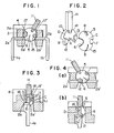
- a switch according to an embodi-" ment of the invention comprises an insulating base 3 supporting a pair of terminals la, lb having ends 2a, 2b projecting into a cavity defined in the insulating base 3 and a cover 4 fitted over the insulating base 3, and a movable conductive contact 5 fitted in the cavity.
- the contact 5 is in the form of a parti-spherical plate having in its peripheral marginal edge a recess 6 for breaking off a current flowing between the terminals la, lb.
- the peripheral marginal edge of the contact 5 also has angularly spaced recesses 7, 8 serving to attach the contact 5 to the slide plate 10, and a slit 9 for adjusting the resilient force of the contact 5.
- the current-breaking recess 6 doubles as a recess for attaching the contact 5.
- the contact 5 is formed by pressing a plate of a metal such as an alloy of copper and rhodium into a parti-spherical plate.
- the peripheral marginal edge of the parti-spherical plate is held in contact with sides 2a', 2b' of the terminal ends 2a, 2b.
- the peripheral marginal edge of the contact 5 bites into the sides 2a', 2b' for good electrical contact therewith.
- the peripheral edge may be cut into a knife edge for more reliable electrical contact.
- the current-breaking recess 6 is positioned such that it opens toward a resin wall 3a of the insulating base 3 when a knob 11 of the switch is displaced to the right as shown in FIG. 1.
- the recess 6 is located at the side 2a' of the terminal end 2a. With the side 2a' positioned in the recess 6, the terminals 2a, 2b are electrically disconnected from each other.
- the slide plate 10 illustrated in FIG. 2 serves to facilitate rotation of the contact 5.
- the slide plate 10 is made of synthetic resin and is in the form of a disc having a lower sectoral portion cut away.
- the knob 11 is mounted on the slide plate 10.
- the slide plate 10 has projections 12, 13 and 14 which can be received in the recesses 6, 7 and 8, respectively.
- the contact 5 is mounted on the slide plate 10 with the projections 12, 13 and 14 fitted respectively in the recesses 6, 7 and 8.
- the peripheral marginal edge of the contact 5 is held agaisnt a surface A of the slide plate 10.
- a lower peripheral edge 15 of the contact 5 projects downwardly of the slide plate 10 into abutment against the sides 2a', 2b' of the terminal ends.
- the projection 12 which fits in the current-breaking recess 6 has a rear surface B lying flush with the surface A of the slide plate 10.
- the rear surfce B is brought into abutment against the side 2a' of the terminal end 2a.
- the contact 5 as mounted on the slide plate 10 is fitted in a gap or clearance defined between resin walls 16, 16' of the insulating base 3.
- the distance L 1 between a crest C of the parti-spherical surface of the contact 5 and a rear surface D (sliding surface) of the slide plate 10 is larger than the distance 1 1 between the resin walls 16, 16'.
- the contact 5 Upon angular movement of the slide plate 10, the contact 5 is turned about the crest C while being guided by edges 17, 17' (FIG. 1) and an edge 18 of the cover 4, during which time the peripheral marginal edge of the contact 5 is pressed against the sides 2a', 2b' as it rotates in a plane defined by the sides 2a', 2b'.
- the peripheral edge 15 can be pressed against the sides 2a', 2b' of the terminal ends under increased pressure in biting engagement therewith for good electrical contact therebetween.
- the slit : '9 in the contact 5 allows the peripheral edge 15 to be stably and uniformly held against the sides 2a', 2b' of the terminal ends under adjusted resilient forces even if the sides 2a', 2b' are staggered in position.
- peripheral edge 15 of the contact 5 is held in biting engagement with the sides 2a', 2b' under high pressure, good electrical connection is assured between the contact 5 and the sides 2a', 2b' even if the sides 2a', 2b' have thereon layers of flux, oxides, or other impurities which could otherwise obstruct such electrical connection.
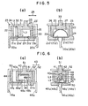
- FIGS. 5(a) and 5(b) show a switch according to another embodiment.
- the switch has an insulating base 22 supporting thereon terminals 20a, 20b having ends 21a, 21b, respectively, which project into a cavity 24 defined jointly by the insulating base 22 and a cover 23 fitted over the insulating base 22, and a movable conductive contact 25 disposed in the cavity 24, the movable conductive contact 25 being in the form of an arcuate construction pressed from a rectangular conductive metal plate.
- the contact 25 is fitted in a recess 27 in a slide member 26, and oriented such that it looks arcuately when viewed in the direction of the arrowheads 28 along which the slide member 26 slides or the terminal ends are spaced from each other.
- the contact 25 has ends 29 held in abutment against upper surfaces -21a', 21b' of the ends 21a, 21b of the terminals 20a, 20b.
- the ends 29 project beyond a lower end 30 of the slide member 26, and the distance L 2 between the ends 29 and an upper end 31 of the slide member 26 is larger than the vertical dimension 1 2 of the cavity 24.
- the slide member 26 has a side 32 which is of a vertical length slightly smaller than the dimension 12.
- the contact 25 is in the form of a resilient arcuate metal plate, the ends 29 thereof are held in biting engagement with the upper surfaces 21a', 21b' for good electrical connection.
- the ends 29 may be cut into the shape of a knife edge for better electrical connection.
- FIGS. 5(a) and 5(b) Operation of the switch shown in FIGS. 5(a) and 5(b) will . .be described.
- the contact 25 is displaced out of contact with the upper surface 21a' of the end of the terminal 20a, and hence the terminals 20a, 20b are electrically disconnected from each other.
- the knob 33 is slid to the left to move the contact 25 slidably leftward, the ends 29 of the contact 25 are brought over the upper surface 21a' of the terminal end 21a, whereupon the terminals 20a, 20b are electrically interconnected.
- the ends 29 of the contact 25 are pressed strongly against the upper surfaces 21a', 21b' under high pressure in biting engagement therewith.
- a movable conductive contact 40 is formed from a rectangular conductive metal plate into an arcuate structure with an end portion 40a extending rectilinearly.
- the movable conductive contact 40 is fitted in a recess 42 in a slide member 41.
- the contact 40 is positioned such that it looks arcuately when viewed in the direction of the arrowheads 43 along which the slide member 41 is slidable or the terminal ends 47a, 47b are spaced from each other, the member 41 being disposed on an insulating base 44.
- the contact 40 has an end 45 held in frictional contact with arms 48a', 48b' of L-shaped contact members 48a, 48b mounted on ends 47a, 47b, respectively, of terminals 46a, 46b supported on the insulating base 44.
- the arms 48a', 48b' extend into a cavity 50 in the insulating base 44.
- the distance L 3 between an arcuate crest 40b of the contact 40 held against a resin wall 49 of the recess 42 in the slide member 41 and a distal edge of the end 45 of the contact 40 is larger than the distance 1 3 between the resin wall 49 and the arms 48a', 48b' of the contact members 48a, 48b. Therefore, the contact 40 as mounted in the slide member 41 and inserted forcibly between the arms 48a', 48b' projecting into the cavity 50 and the resin wall 49, has its end 45 resiliently held against the arms 48a', 48b'.
- a knob 51 on the slide member 41 is slid in the direction of one of the arrowheads 43, the slide member 41 is guided by an inner surface 52' of a cover 52 so as to slide over the arms 48a', 48b'.
- the contact 40 may be held in frictional engagement directly with the terminal ends 47a, 47b which may be L-shaped in cross section.
- the end 45 of the contact 40 is shown as contacting the arms 48a', 48b' of the contact members 48a, 48b, and the terminals 46a, 46b are electrically connected to each other.
- the knob 51 is displaced to slide the contact 40 to the left, the end 45 of the contact 40 is disengaged from one of the arms 48b', whereupon the terminals 46a, 46b are electrically disconnected from each other.
- FIGS. 7(a) and 7(b) illustrate a switch according to a still further embodiment of the present invention.
- the switch of FIGS. 7(a) and 7(b) is basically of the same construction as that of the switch shown in FIGS. 6(a) and 6(b).
- the switch has an insulating base 62 supporting terminals 60a, 60b having ends 61a, 61b, a cover 63 fitted over the insulating base 62, and a contact 65 disposed in a cavity 64 defined jointly by the insulating base 62 and the cover 63.
- the contact 65 is formed from a rectangular conductive metal plate into an arcuate construction with a rectilinear end portion 65a, an arangement similar to that shown in FIGS.
- the contact 65 is mounted on the insulating base 62 such that it looks arcuate when viewed in the direction along which a slide member 66 with the contact 65 mounted therein is slidable.
- the contact 65 has an end 67 held in frictional engagement with projecting arms 68a'," 68b' of L-shaped contact members 68a, 68b fixedly mounted on the ends 61a, 61b of the terminals 60a, 60b.
- the contact 65 When the contact 65 is mounted in the slide member 66, the distance L 4 between an arcuate crest 65bof the contact 65 which is held against a resin wall 69 of the insulating base 62 and a distal edge of the end 67 of the contact 65 is larger than the distance 14 between the resin wall 69 and the arms 68a', 68b'. Therefore, the contact 65 as it is mounted in the slide member 66 and force-fitted between the resin wall 69 of the cavity 64 and the arms.68a', 68b', has its end 67 pressed resiliently against the arms 68a', 68b'.
- Angular movement of a knob 71 of a toggle lever 70 engaging the slide member 66 in the directions of the arrowheads 72 causes the contact 65 to slide on the arms 68a', - 68b' in the directions of the arrowheads 73.
- the end 67 of the contact 65 may be cut into the form of a knife edge for better electrical connection with the arms 68a', 68b'.
- the terminal ends 61a, 61b may be cross-sectionally L-shaped and the contact 65 may be elongated in the longitudinal direction for direct frictional contact with the terminal ends 61a, 61b.
- the contact 65 is mounted in the slide member 66 and press-fitted between the resin wall 69 of the cavity 64 and the arms 68a', 68b' for easily sliding movement, the slide member 66 may be dispensed with and the contact 65 may directly be inserted between the wall 69 and the arms 68a', 68b'.
Landscapes
- Slide Switches (AREA)
Applications Claiming Priority (6)
| Application Number | Priority Date | Filing Date | Title |
|---|---|---|---|
| JP73324/81 | 1981-05-14 | ||
| JP56073324A JPS57187816A (en) | 1981-05-14 | 1981-05-14 | Switch |
| JP1266682U JPS58115038U (ja) | 1982-02-01 | 1982-02-01 | トグル式スイツチ |
| JP12666/82U | 1982-02-01 | ||
| JP12665/82U | 1982-02-01 | ||
| JP1266582U JPS58115029U (ja) | 1982-02-01 | 1982-02-01 | スライド式スイツチ |
Publications (3)
| Publication Number | Publication Date |
|---|---|
| EP0068118A2 true EP0068118A2 (fr) | 1983-01-05 |
| EP0068118A3 EP0068118A3 (en) | 1984-05-09 |
| EP0068118B1 EP0068118B1 (fr) | 1987-01-21 |
Family
ID=27279932
Family Applications (1)
| Application Number | Title | Priority Date | Filing Date |
|---|---|---|---|
| EP82104006A Expired EP0068118B1 (fr) | 1981-05-14 | 1982-05-07 | Construction simplifiée d'interrupteur électrique |
Country Status (8)
| Country | Link |
|---|---|
| US (1) | US4403127A (fr) |
| EP (1) | EP0068118B1 (fr) |
| KR (1) | KR890000523Y1 (fr) |
| CA (1) | CA1201148A (fr) |
| DE (1) | DE3275251D1 (fr) |
| GB (1) | GB2101405B (fr) |
| HK (2) | HK105588A (fr) |
| SG (1) | SG71685G (fr) |
Cited By (1)
| Publication number | Priority date | Publication date | Assignee | Title |
|---|---|---|---|---|
| FR2587866A1 (fr) * | 1985-09-21 | 1987-03-27 | Bosch Gmbh Robert | Dispositif de branchement pour un appareil d'enregistrement et/ou de reproduction de television |
Families Citing this family (5)
| Publication number | Priority date | Publication date | Assignee | Title |
|---|---|---|---|---|
| DE19609973A1 (de) * | 1996-03-14 | 1997-09-18 | Teves Gmbh Alfred | Antriebsvorrichtung für Scheibenwischer mit einem Parkstellungsschalter |
| USD448008S1 (en) | 1998-11-20 | 2001-09-18 | Airpax Corporation, Llc | Toggle switch stop |
| US6351088B1 (en) | 2000-03-09 | 2002-02-26 | Valeo Electrical Systems, Inc. | Non-reversing wiper park switch for wiper drive apparatus |
| US6737593B1 (en) | 2000-07-28 | 2004-05-18 | Valeo Electrical Systems, Inc. | Non-reversing windshield wiper motor park switch |
| US9588496B2 (en) * | 2012-03-14 | 2017-03-07 | Tom Kodat | Device for assisting user in consumption of a substance at a correct time interval |
Family Cites Families (9)
| Publication number | Priority date | Publication date | Assignee | Title |
|---|---|---|---|---|
| US2002587A (en) * | 1931-05-20 | 1935-05-28 | Sachs Joseph | Electric circuit controlling mechanism |
| DE742584C (de) * | 1942-01-10 | 1943-12-07 | Elektrotechnischer Bedarfsarti | Stufenschalter |
| US2808476A (en) * | 1954-06-25 | 1957-10-01 | Gen Motors Corp | Electric switch |
| US2747166A (en) * | 1954-12-13 | 1956-05-22 | Collins Radio Co | Interlocked flexible contact assembly for shaft |
| US3238319A (en) * | 1961-09-13 | 1966-03-01 | American Mach & Foundry | Switch with axially spaced angularly offset rotary wiper contacts |
| JPS5210459B2 (fr) * | 1974-01-11 | 1977-03-24 | ||
| US4082925A (en) * | 1976-03-31 | 1978-04-04 | Cts Corporation | Rotary switch |
| JPS5848748Y2 (ja) * | 1977-07-19 | 1983-11-08 | アルプス電気株式会社 | スイツチ |
| DE2831204C2 (de) * | 1978-07-15 | 1980-05-29 | Standard Elektrik Lorenz Ag, 7000 Stuttgart | Miniatur-Stufenschalter |
-
1982
- 1982-04-23 US US06/371,227 patent/US4403127A/en not_active Expired - Fee Related
- 1982-04-28 CA CA000401858A patent/CA1201148A/fr not_active Expired
- 1982-04-28 GB GB08212246A patent/GB2101405B/en not_active Expired
- 1982-05-07 EP EP82104006A patent/EP0068118B1/fr not_active Expired
- 1982-05-07 DE DE8282104006T patent/DE3275251D1/de not_active Expired
-
1985
- 1985-09-28 SG SG716/85A patent/SG71685G/en unknown
-
1988
- 1988-11-15 KR KR2019880018561U patent/KR890000523Y1/ko not_active Expired
- 1988-12-29 HK HK1055/88A patent/HK105588A/xx unknown
-
1991
- 1991-03-07 HK HK161/91A patent/HK16191A/xx unknown
Cited By (1)
| Publication number | Priority date | Publication date | Assignee | Title |
|---|---|---|---|---|
| FR2587866A1 (fr) * | 1985-09-21 | 1987-03-27 | Bosch Gmbh Robert | Dispositif de branchement pour un appareil d'enregistrement et/ou de reproduction de television |
Also Published As
| Publication number | Publication date |
|---|---|
| HK105588A (en) | 1989-01-06 |
| EP0068118A3 (en) | 1984-05-09 |
| CA1201148A (fr) | 1986-02-25 |
| SG71685G (en) | 1986-05-02 |
| DE3275251D1 (en) | 1987-02-26 |
| GB2101405A (en) | 1983-01-12 |
| GB2101405B (en) | 1985-06-12 |
| EP0068118B1 (fr) | 1987-01-21 |
| KR890000523Y1 (ko) | 1989-03-10 |
| HK16191A (en) | 1991-03-15 |
| US4403127A (en) | 1983-09-06 |
Similar Documents
| Publication | Publication Date | Title |
|---|---|---|
| US5693924A (en) | Switching contact mechanism with wipe and backwipe | |
| US3294932A (en) | Wiping contact switch | |
| US4357511A (en) | Modular push-button switch with lighted push-button element | |
| US4403127A (en) | Toggle switch having pressure contact | |
| US4789764A (en) | Pushbutton switch with resilient extensible pivotable contact element | |
| US4767896A (en) | Stamped circuitry assembly | |
| GB2061005A (en) | Switch unit | |
| US4659157A (en) | Stamped circuitry assembly | |
| US4072841A (en) | Electrical switches | |
| EP0011413A1 (fr) | Interrupteur | |
| US2399462A (en) | Electric switch | |
| US4072839A (en) | Slide switch type assembly having two part housing | |
| GB1508507A (en) | Connector assembly for printed circuit board | |
| US4728759A (en) | Stamped circuitry and adjustable rotary switch assembly | |
| US4605830A (en) | Cammed wire snap switch | |
| US4725702A (en) | Miniature switch with self-aligning movable contactor | |
| JPH0129948Y2 (fr) | ||
| JPS5824349Y2 (ja) | スイッチ機構 | |
| US3668342A (en) | Can opener switch | |
| JPH0229635Y2 (fr) | ||
| GB2153592A (en) | Electrical switches | |
| JPH02997Y2 (fr) | ||
| GB2045531A (en) | Electric switch | |
| JP2552922Y2 (ja) | プッシュスライド兼用スイッチ | |
| JPH0326595Y2 (fr) |
Legal Events
| Date | Code | Title | Description |
|---|---|---|---|
| PUAI | Public reference made under article 153(3) epc to a published international application that has entered the european phase |
Free format text: ORIGINAL CODE: 0009012 |
|
| AK | Designated contracting states |
Designated state(s): CH DE FR GB IT LI |
|
| PUAL | Search report despatched |
Free format text: ORIGINAL CODE: 0009013 |
|
| AK | Designated contracting states |
Designated state(s): CH DE FR GB IT LI |
|
| 17P | Request for examination filed |
Effective date: 19840927 |
|
| ITF | It: translation for a ep patent filed | ||
| GRAA | (expected) grant |
Free format text: ORIGINAL CODE: 0009210 |
|
| AK | Designated contracting states |
Kind code of ref document: B1 Designated state(s): CH DE FR IT LI |
|
| REF | Corresponds to: |
Ref document number: 3275251 Country of ref document: DE Date of ref document: 19870226 |
|
| ET | Fr: translation filed | ||
| PLBE | No opposition filed within time limit |
Free format text: ORIGINAL CODE: 0009261 |
|
| STAA | Information on the status of an ep patent application or granted ep patent |
Free format text: STATUS: NO OPPOSITION FILED WITHIN TIME LIMIT |
|
| 26N | No opposition filed | ||
| REG | Reference to a national code |
Ref country code: CH Ref legal event code: PFA Free format text: OTAX CO., LTD |
|
| ITPR | It: changes in ownership of a european patent |
Owner name: CAMBIO RAGIONE SOCIALE;OTAX CO. LTD |
|
| REG | Reference to a national code |
Ref country code: FR Ref legal event code: CD |
|
| ITTA | It: last paid annual fee | ||
| PGFP | Annual fee paid to national office [announced via postgrant information from national office to epo] |
Ref country code: FR Payment date: 19920513 Year of fee payment: 11 |
|
| PGFP | Annual fee paid to national office [announced via postgrant information from national office to epo] |
Ref country code: CH Payment date: 19920518 Year of fee payment: 11 |
|
| PGFP | Annual fee paid to national office [announced via postgrant information from national office to epo] |
Ref country code: DE Payment date: 19920730 Year of fee payment: 11 |
|
| PG25 | Lapsed in a contracting state [announced via postgrant information from national office to epo] |
Ref country code: LI Effective date: 19930531 Ref country code: CH Effective date: 19930531 |
|
| PG25 | Lapsed in a contracting state [announced via postgrant information from national office to epo] |
Ref country code: FR Effective date: 19940131 |
|
| REG | Reference to a national code |
Ref country code: CH Ref legal event code: PL |
|
| PG25 | Lapsed in a contracting state [announced via postgrant information from national office to epo] |
Ref country code: DE Effective date: 19940201 |
|
| REG | Reference to a national code |
Ref country code: FR Ref legal event code: ST |