EP0068140A1 - Auslassventil in Ausblaseinrichtungen für Ausstoss- und Ablaufrohre von U-Booten - Google Patents
Auslassventil in Ausblaseinrichtungen für Ausstoss- und Ablaufrohre von U-Booten Download PDFInfo
- Publication number
- EP0068140A1 EP0068140A1 EP82104490A EP82104490A EP0068140A1 EP 0068140 A1 EP0068140 A1 EP 0068140A1 EP 82104490 A EP82104490 A EP 82104490A EP 82104490 A EP82104490 A EP 82104490A EP 0068140 A1 EP0068140 A1 EP 0068140A1
- Authority
- EP
- European Patent Office
- Prior art keywords
- section
- stroke
- valve body
- cross
- shut
- Prior art date
- Legal status (The legal status is an assumption and is not a legal conclusion. Google has not performed a legal analysis and makes no representation as to the accuracy of the status listed.)
- Granted
Links
- 230000007704 transition Effects 0.000 claims description 6
- 230000009189 diving Effects 0.000 description 3
- 230000008859 change Effects 0.000 description 2
- 230000009471 action Effects 0.000 description 1
- 230000006978 adaptation Effects 0.000 description 1
- 238000013016 damping Methods 0.000 description 1
- 230000001419 dependent effect Effects 0.000 description 1
- 230000000694 effects Effects 0.000 description 1
- 238000000034 method Methods 0.000 description 1
- 230000008569 process Effects 0.000 description 1
Images

Classifications
-
- F—MECHANICAL ENGINEERING; LIGHTING; HEATING; WEAPONS; BLASTING
- F41—WEAPONS
- F41F—APPARATUS FOR LAUNCHING PROJECTILES OR MISSILES FROM BARRELS, e.g. CANNONS; LAUNCHERS FOR ROCKETS OR TORPEDOES; HARPOON GUNS
- F41F3/00—Rocket or torpedo launchers
- F41F3/08—Rocket or torpedo launchers for marine torpedoes
- F41F3/10—Rocket or torpedo launchers for marine torpedoes from below the surface of the water
Definitions
- the invention relates to an outlet valve in blow-out devices for ejection and drain pipes of submarines for ejecting weapons by means of compressed gas, which can be supplied from associated compressed gas containers and controlled via a circuit arrangement, the speed of the opening stroke of the shut-off element being predetermined by the system.
- valves of this type there is the problem of performing a control function in addition to the actual opening functions in order to eject the weapons to be ejected at all diving depths at predetermined speeds. It is therefore necessary to greatly change the throughput quantities and thus the outlet cross section to match the depth of the dive.
- the object of the invention is to provide an outlet valve of the generic type which enables a simple mechanical structure and essentially no longer requires an adaptation of the opening speed to different diving depths by additional settings.
- shut-off element projects as a peg-like valve body into an outlet bore and the peg-like valve body and / or the outlet bore has a plurality of step-like shoulders such that that an opening cross-section widened discontinuously depending on the stroke.
- the passage cross section for the pressurized gas is expanded in several discontinuous jumps at a constant speed of the exhaust valve.
- the shoulders formed be designed to be approximately constant over a lifting section.
- transition areas with essentially linear or square cross-sectional widenings are formed between the individual paragraphs.
- end region of the pin-like valve body is designed as a conical extension.
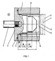
- a valve housing 1 shown is provided with an outlet bore 2 and has a shut-off device 3 with an end seal 4 which, in the closed state, bears against a valve seat 5 and thus prevents gas passage from a pressure chamber 6 into the outlet bore 2.
- the shut-off device 3 has a peg-like valve body 19 which projects into the outlet bore 2 in the idle state. Via a valve stem 7, the outlet valve is opened at the start of a blow-out process with a system-dependent opening speed, not shown, which is normally approximately constant.
- the passage on the axial seal 4 is released and the opening cross section according to FIG. 1 is determined during a first part 8 of the stroke by the diameter of the outlet bore 2 and the diameter 9 of the valve body 19.
- a second constant cross-section is effective over part 11 of the stroke.
- the size of the cross section is determined by opposing diameters 2 and 12. This is followed by a further transition area 13 and a third cross section in the area of the partial stroke 14, the size of which is determined by the diameters 2 and 15.
- the conical extension 16 takes effect, with which the maximum possible opening cross section of the valve is achieved.
- the diameter 2 of the outlet bore extends continuously over the entire length 17 of the valve body 19, but the intended valve action is also achieved if the diameter 2 is only present over a short area 18 in the vicinity of the valve seat 5.
- valve housing 1 is an embodiment with the valve housing 1, the shut-off device 3 with a cylindrical pin-like valve body 19 and a truncated cone 16 presented as a conclusion.
- the total controlled valve lift is determined by the length 20 of the valve body 19.
- the partial lengths in which the individual essentially constant cross sections are effective are determined by the lengths 21, 22, 23.
- the associated cross sections result from the pin diameter 24 on the one hand and the step diameters 25, 26, 27 on the other hand from the outlet bore.
- the transitions between the individual cross sections are assumed to be linear here, which means a parabolic change with regard to the diameter. Of course, this can also be replaced approximately by circular transitions.
Landscapes
- Engineering & Computer Science (AREA)
- Ocean & Marine Engineering (AREA)
- General Engineering & Computer Science (AREA)
- Lift Valve (AREA)
- Sliding Valves (AREA)
Abstract
Description
- Die Erfindung bezieht sich auf ein Auslaßventil in Ausblaseinrichtungen für Ausstoß- und Ablaufrohre von U-Booten zum Ausstoßen von Waffen mittels Druckgas, das aus zugeordneten Druckgasbehältern zuführbar und über eine Schaltungsanordnung steuerbar ist, wobei die Geschwindigkeit des Öffnungshubes des Absperrorgans systembedingt vorgegeben ist.
- Bei Ventilen dieser Art besteht das Problem, neben den eigentlichen Öffnungsfunktionen auch eine Steuerfunktion zu erfüllen, um die auszustoßenden Waffen bei allen Tauchtiefen mit vorgegebenen Geschwindigkeiten auszustoßen. Hierbei ist es somit erforderlich, die Durchsatzmengen und damit den Auslaßquerschnitt in Anpassung an die Tauchtiefe stark zu verändern. Es ist hierzu beispielsweise bekannt geworden, durch eine hydraulische Dämpfungseinrichtung die Öffnungsgeschwindigkeit des Auslaßventils in einem einstellbaren Geschwindigkeitsbereich konstant zu halten, wobei dieser Geschwindigkeitsbereich an die jeweilige Tauchtiefe angepaßt werden muß.
- Die Aufgabe der Erfindung ist es, ein Auslaßventil der gattungsgemäßen Art zu schaffen, das einen einfachen mechanischen Aufbau ermöglicht und eine Anpassung der Öffnungsgeschwindigkeit an unterschiedliche Tauchtiefen durch zusätzliche Einstellungen im wesentlichen nicht mehr erforderlich macht.
- Die Lösung dieser Aufgabe erfolgt erfindungsgemäß dadurch, daß das Absperrorgan als zapfenartiger Ventilkörper in eine Austrittsbohrung hineinragt und der zapfenartige Ventilkörper und /oder die Austrittsbohrung mehrere stufenartige Absätze derart aufweist, daß sich ein Öffnungsquerschnitt hubabhängig diskontinuierlich erweitert.
- Hierdurch wird bei konstanter Hübgeschwindigkeit des Auslaßventils der Durchtrittsquerschnitt für das Preßgas in mehreren diskontinuierlichen Sprüngen erweitert.
- Weiterhin wird zur Erzielung eines abschnittweisen konstanten Öffnungsquerschnittes vorgeschlagen, daß die gebildeten Absätze über einen Hubabschnitt annähernd konstant ausgebildet sind.
- Zur weiteren Beeinflussung des Durchtrittsquerschnittes ist vorgesehen, daß zwischen den einzelnen Absätzen Übergangsbereiche mit im wesentlichen linearen oder quadratischen Querschnittserweiterungen ausgebildet sind. Zusätzlich wird vorgeschlagen, daß der Endbereich des zapfenartigen Ventilkörpers als kegelförmiger Ansatz ausgebildet ist.
- Es hat sich gezeigt, daß eine besonders vorteilhafte Ausgestaltung der Absätze dadurch geschaffen wird, daß der in Hubrichtung wirksame erste Absatz einen Öffnungsquerschnitt kleiner als 7 % und die nachfolgenden Absätze jeweils einen Öffnungsquerschnitt größer als 7 % des Maximalquerschnittes freigeben.
- In der Zeichnung sind Ausführungsbeispiele der erfindungsgemäßen Ausbildung schematisch dargestellt. Es zeigen:
- Figur 1 einen Schnitt durch ein Absperrorgan mit einem sich stufenförmig verjüngenden Ventilkörper in einer zylindrischen Austrittsbohrung und
- Figur 2 einen Schnitt durch ein Absperrorgan mit einem zylindrischen Ventilkörper und einer sich stufenförmig verjüngenden Austrittsbohrung.
- Ein dargestelltes Ventilgehäuse 1 ist mit einer Austrittsbohrung 2 versehen und besitzt ein Absperrorgan 3 mit einer stirnseitigen Dichtung 4, welche im geschlossenen Zustand an einem Ventilsitz 5 anliegt und damit einen Gasdurchtritt aus einem Druckraum 6 in die Austrittsbohrung 2 verhindert. Das Absperrorgan 3 weist einen zapfenartigen Ventilkörper 19 auf, der im Ruhezustand in die Austrittsbohrung 2 hineinragt. Über einen Ventilschaft 7 wird das Auslaßventil bei Einleitung eines Ausblasvorganges mit einer nicht näher dargestellten systembedingten Öffnungsgeschwindigkeit, die im Normalfall in etwa konstant ist, geöffnet. Dabei wird der Durchtritt an der axialen Dichtung 4 freigegeben und der Öffnungsquerschnitt gemäß Fig. 1 während eines ersten Teils 8 des Hubs durch den Durchmesser der Austrittsbohrung 2 und den Durchmesser 9 des Ventilkörpers 19 bestimmt. Nach Durchlaufen eines Übergangsbereiches 10 mit quadratisch mit dem Hub zunehmenden Querschnitt, d.h. kegelförmiger Kontur, wird ein zweiter konstanter Querschnitt über den Teil 11 des Hubes wirksam. Die Größe des Querschnittes wird bestimmt durch sich gegenüberstehende Durchmesser 2 und 12. Daran schließt sich ein weiterer Übergangsbereich 13 und ein dritter Querschnitt im Bereich des Teilhubes 14 an, dessen Größe durch die Durchmesser 2 und 15 festgelegt ist. Nach Überschreiten des Teilhubes 14 wird der kegelförmige Ansatz 16 wirksam, womit der maximal mögliche Öffnungsquerschnitt des Ventils erreicht wird. Der Durchmesser 2 der Austrittsbohrung erstreckt sich fortlaufend über die gesamte Länge 17 des Ventilkörpers 19, die beabsichtigte Ventilwirkung wird jedoch auch dann erreicht, wenn der Durchmesser 2 nur über einen kurzen Bereich 18 in der Nähe des Ventilsitzes 5 vorhanden ist.
- Gemäß Fig. 2 ist eine Ausführungsform mit dem Ventilgehäuse 1, dem Absperrorgan 3 mit einem zylindrischen zapfenartigen Ventilkörper 19 und einem Kegelstumpf 16 als Abschluß dargestellt. In diesem Fall wird der gesamte gesteuerte Ventilhub durch die Länge 20 des Ventilkörpers 19 bestimmt. Die Teillängen, in denen die einzelnen im wesentlichen konstanten Querschnitte wirksam werden, sind bestimmt durch die Längen 21,22,23. Die zugehörigen Querschnitte ergeben sich aus dem Zapfendurchmesser 24 einerseits und den Stufendurchmessern 25, 26,27 andererseits der Austrittsbohrung. Die Übergänge zwischen den einzelnen Querschnitten sind hier linear angenommen, was bezüglich der Durchmesser eine parabolische Änderung bedeutet. Dieses kann natürlich auch näherungsweise durch kreisbogenförmige Übergänge ersetzt werden.
Claims (5)
Applications Claiming Priority (2)
| Application Number | Priority Date | Filing Date | Title |
|---|---|---|---|
| DE3125906 | 1981-07-01 | ||
| DE19813125906 DE3125906A1 (de) | 1981-07-01 | 1981-07-01 | Auslassventil in ausblaseinrichtungen fuer ausstoss- und ablaufrohre von u-booten |
Publications (2)
| Publication Number | Publication Date |
|---|---|
| EP0068140A1 true EP0068140A1 (de) | 1983-01-05 |
| EP0068140B1 EP0068140B1 (de) | 1985-01-23 |
Family
ID=6135837
Family Applications (1)
| Application Number | Title | Priority Date | Filing Date |
|---|---|---|---|
| EP82104490A Expired EP0068140B1 (de) | 1981-07-01 | 1982-05-22 | Auslassventil in Ausblaseinrichtungen für Ausstoss- und Ablaufrohre von U-Booten |
Country Status (2)
| Country | Link |
|---|---|
| EP (1) | EP0068140B1 (de) |
| DE (2) | DE3125906A1 (de) |
Citations (5)
| Publication number | Priority date | Publication date | Assignee | Title |
|---|---|---|---|---|
| DE255966C (de) * | ||||
| US1327614A (en) * | 1917-07-30 | 1920-01-13 | Electric Boat Co | Torpedo-launching apparatus |
| DE1124387B (de) * | 1953-09-11 | 1962-02-22 | Gen Dynamics Corp | Vorrichtung zum Unterwasserabschuss von Geschossen |
| GB978455A (en) * | 1962-06-09 | 1964-12-23 | Junkers & Co | Improvements in or relating to gas flow control valves |
| US3773025A (en) * | 1971-11-02 | 1973-11-20 | Marotta Scientific Controls | Method and apparatus for ejection by compressed gas |
-
1981
- 1981-07-01 DE DE19813125906 patent/DE3125906A1/de not_active Ceased
-
1982
- 1982-05-22 DE DE8282104490T patent/DE3262026D1/de not_active Expired
- 1982-05-22 EP EP82104490A patent/EP0068140B1/de not_active Expired
Patent Citations (5)
| Publication number | Priority date | Publication date | Assignee | Title |
|---|---|---|---|---|
| DE255966C (de) * | ||||
| US1327614A (en) * | 1917-07-30 | 1920-01-13 | Electric Boat Co | Torpedo-launching apparatus |
| DE1124387B (de) * | 1953-09-11 | 1962-02-22 | Gen Dynamics Corp | Vorrichtung zum Unterwasserabschuss von Geschossen |
| GB978455A (en) * | 1962-06-09 | 1964-12-23 | Junkers & Co | Improvements in or relating to gas flow control valves |
| US3773025A (en) * | 1971-11-02 | 1973-11-20 | Marotta Scientific Controls | Method and apparatus for ejection by compressed gas |
Also Published As
| Publication number | Publication date |
|---|---|
| EP0068140B1 (de) | 1985-01-23 |
| DE3125906A1 (de) | 1983-01-20 |
| DE3262026D1 (en) | 1985-03-07 |
Similar Documents
| Publication | Publication Date | Title |
|---|---|---|
| DE3688753T2 (de) | Steuereinrichtung für elektro-hydraulisch betätigte Kraftstoffeinspritzventile. | |
| DE2226175A1 (de) | Öffnung mit hoher Durchflußmenge für Spulenventile | |
| EP0302068B1 (de) | Rückschlagventil | |
| DE3914486A1 (de) | Verfahren zur herstellung einer ventilnadel und ventilnadel | |
| DE10105674A1 (de) | Kraftstoffeinspritzdüse für eine Brennkraftmaschine | |
| EP0137095B1 (de) | Ausblaseinrichtung für Ausstoss- und Ablaufrohre von U-Booten | |
| EP0068140B1 (de) | Auslassventil in Ausblaseinrichtungen für Ausstoss- und Ablaufrohre von U-Booten | |
| EP0222057B1 (de) | Überdruckventil für einen pyrotechnischen Gasgenerator | |
| DE1175576B (de) | Geschoss bzw. Granate zum Aufstecken auf das Laufende einer Feuerwaffe | |
| DE10315967A1 (de) | Kraftstoffeinspritzventil für Brennkraftmaschinen | |
| EP0066734B1 (de) | Ausblas-Einrichtung für Ausstoss- und Ablaufrohre von U-Booten | |
| DE2628704A1 (de) | Abflussvorrichtung fuer die entleerung eines ein stroemungsmittel unter druck enthaltenden behaelters | |
| DE3809954C1 (en) | Device for the hydraulic opening of a lifting valve | |
| DE3346182C2 (de) | ||
| DE1147873B (de) | Zerlegerzuender fuer Drallgeschosse | |
| EP3577335B1 (de) | Anordnung | |
| DE3137720A1 (de) | Stellventil, insbesondere zur steuerung und regelungvon dampfturbinen | |
| DE2720104C2 (de) | Direktgesteuertes Druckbegrenzungsventil für hydraulische Anlagen | |
| EP3146280B1 (de) | Expansionsventil | |
| EP0227854B1 (de) | Druckmindervorrichtung | |
| DD243967A5 (de) | Steuerventil fuer doppelwirkende pneumatische arbeitszylinder | |
| DE3048598A1 (de) | Anordnung bei rueckstossfreien waffen | |
| DE3231528C1 (de) | Steuersystem fuer eine fluegellose Lenkmunition | |
| EP1685321B1 (de) | Ventil zum steuern eines fluids | |
| DE3406369A1 (de) | Druckbegrenzungsventil |
Legal Events
| Date | Code | Title | Description |
|---|---|---|---|
| PUAI | Public reference made under article 153(3) epc to a published international application that has entered the european phase |
Free format text: ORIGINAL CODE: 0009012 |
|
| AK | Designated contracting states |
Designated state(s): BE DE FR GB IT NL SE |
|
| 17P | Request for examination filed |
Effective date: 19830325 |
|
| ITF | It: translation for a ep patent filed | ||
| GRAA | (expected) grant |
Free format text: ORIGINAL CODE: 0009210 |
|
| AK | Designated contracting states |
Designated state(s): BE DE FR GB IT NL SE |
|
| REF | Corresponds to: |
Ref document number: 3262026 Country of ref document: DE Date of ref document: 19850307 |
|
| ET | Fr: translation filed | ||
| PLBE | No opposition filed within time limit |
Free format text: ORIGINAL CODE: 0009261 |
|
| STAA | Information on the status of an ep patent application or granted ep patent |
Free format text: STATUS: NO OPPOSITION FILED WITHIN TIME LIMIT |
|
| 26N | No opposition filed | ||
| PGFP | Annual fee paid to national office [announced via postgrant information from national office to epo] |
Ref country code: SE Payment date: 19890224 Year of fee payment: 8 |
|
| PGFP | Annual fee paid to national office [announced via postgrant information from national office to epo] |
Ref country code: FR Payment date: 19890519 Year of fee payment: 8 |
|
| ITTA | It: last paid annual fee | ||
| PGFP | Annual fee paid to national office [announced via postgrant information from national office to epo] |
Ref country code: NL Payment date: 19890531 Year of fee payment: 8 Ref country code: GB Payment date: 19890531 Year of fee payment: 8 |
|
| PGFP | Annual fee paid to national office [announced via postgrant information from national office to epo] |
Ref country code: BE Payment date: 19890710 Year of fee payment: 8 |
|
| PG25 | Lapsed in a contracting state [announced via postgrant information from national office to epo] |
Ref country code: GB Effective date: 19900522 |
|
| PG25 | Lapsed in a contracting state [announced via postgrant information from national office to epo] |
Ref country code: SE Effective date: 19900523 |
|
| PG25 | Lapsed in a contracting state [announced via postgrant information from national office to epo] |
Ref country code: BE Effective date: 19900531 |
|
| BERE | Be: lapsed |
Owner name: KRUPP MAK MASCHINENBAU G.M.B.H. Effective date: 19900531 |
|
| PG25 | Lapsed in a contracting state [announced via postgrant information from national office to epo] |
Ref country code: NL Effective date: 19901201 |
|
| GBPC | Gb: european patent ceased through non-payment of renewal fee | ||
| NLV4 | Nl: lapsed or anulled due to non-payment of the annual fee | ||
| PG25 | Lapsed in a contracting state [announced via postgrant information from national office to epo] |
Ref country code: FR Effective date: 19910131 |
|
| REG | Reference to a national code |
Ref country code: FR Ref legal event code: ST |
|
| EUG | Se: european patent has lapsed |
Ref document number: 82104490.6 Effective date: 19910115 |
|
| PGFP | Annual fee paid to national office [announced via postgrant information from national office to epo] |
Ref country code: DE Payment date: 19970522 Year of fee payment: 16 |
|
| PG25 | Lapsed in a contracting state [announced via postgrant information from national office to epo] |
Ref country code: DE Free format text: LAPSE BECAUSE OF NON-PAYMENT OF DUE FEES Effective date: 19990302 |