EP0068165A2 - Brûleur pour découper et/ou dégrossir thermochimiquement des pièces à usiner en acier - Google Patents
Brûleur pour découper et/ou dégrossir thermochimiquement des pièces à usiner en acier Download PDFInfo
- Publication number
- EP0068165A2 EP0068165A2 EP82104845A EP82104845A EP0068165A2 EP 0068165 A2 EP0068165 A2 EP 0068165A2 EP 82104845 A EP82104845 A EP 82104845A EP 82104845 A EP82104845 A EP 82104845A EP 0068165 A2 EP0068165 A2 EP 0068165A2
- Authority
- EP
- European Patent Office
- Prior art keywords
- nozzle
- bore
- burner according
- outlet
- diameter
- Prior art date
- Legal status (The legal status is an assumption and is not a legal conclusion. Google has not performed a legal analysis and makes no representation as to the accuracy of the status listed.)
- Granted
Links
Images

Classifications
-
- F—MECHANICAL ENGINEERING; LIGHTING; HEATING; WEAPONS; BLASTING
- F23—COMBUSTION APPARATUS; COMBUSTION PROCESSES
- F23D—BURNERS
- F23D14/00—Burners for combustion of a gas, e.g. of a gas stored under pressure as a liquid
- F23D14/46—Details
- F23D14/48—Nozzles
- F23D14/56—Nozzles for spreading the flame over an area, e.g. for desurfacing of solid material, for surface hardening or for heating workpieces
-
- F—MECHANICAL ENGINEERING; LIGHTING; HEATING; WEAPONS; BLASTING
- F23—COMBUSTION APPARATUS; COMBUSTION PROCESSES
- F23D—BURNERS
- F23D14/00—Burners for combustion of a gas, e.g. of a gas stored under pressure as a liquid
- F23D14/46—Details
- F23D14/48—Nozzles
- F23D14/52—Nozzles for torches; for blow-pipes
- F23D14/54—Nozzles for torches; for blow-pipes for cutting or welding metal
Definitions
- the invention relates to a burner for the thermal separation and / or planing of workpieces made of steel with an oxygen jet, the burner consisting essentially of a nozzle part and a holding part.
- burners which are used for a wide variety of work, e.g. Cutting thinner, thicker or thickest steel workpieces or for planing narrow joints up to the widest areas on steel workpieces.
- thermochemical cutting and planing of workpieces made of steel the aim is to achieve ever greater performance, i.e. To achieve greater flame speeds, greater flame width, greater flame depth, greater cutting speeds and greater cutting thicknesses, led to a large number of burner developments, including issues of the lowest possible gas consumption and narrow kerf widths and problems of safety, environmental friendliness, e.g. in terms of noise generation and less harmful exhaust gases, as well as a long service life of the nozzles.
- the cutting speeds achieved cannot be regarded as satisfactory, because with sufficient heating of the reaction site by the burner heating and the exo arising during cutting thermal heat development, the cutting speeds, despite the greatest oxygen purity, only reach a fraction of the chemical reaction rate.
- This stems from the fact that the iron oxide skin that forms over the reactive iron always has to be removed by the kinetic energy of the cutting oxygen jet.
- the kinetic energy of the cutting oxygen jet Obtained from the conversion of the pressure of the supplied oxygen, however, there are restrictions due to friction and shock losses when the nozzle is narrowed or expanded, and due to insufficient jet formation.
- Another problem is the formation of the kerf. If the kerf width is too large, a lot of material is lost, which also increases the formation of the beard and thus the effort increased for rework.
- the invention is therefore based on the object of making available a burner which, in the case of insensitivity to pressure fluctuations, is distinguished by a simple, inexpensive design with a long service life and enables the formation of thin kerfs at a maximum working speed. In this way, the smallest possible beards are created with sharp edges and few pearls on the top, so that little rework is required.
- this is achieved in a burner for thermochemical burning and planing of thick workpieces made of steel, preferably between 51 to 600 mm, with an oxygen jet, the burner consisting essentially of a nozzle and a holding part, in that the nozzle part has a clear definition cylindrically shaped nozzle bore for the cutting oxygen jet with a short, no greater than 10 mm to 0 going length, preferably between 0.5 to 5 mm, and with a comparatively small diameter, equal to or less than 4 mm, preferably between 1.5 to 3, 6 mm.
- a cylindrical outlet bore for jet formation is provided on the output side of the bore, which represents a slight expansion compared to the nozzle bore.
- An expedient design also consists in the fact that the outlet bore widens conically towards the outlet side, the conical widening being between 5 and 10 °, preferably 7 °.
- the design of the transition from the inlet bore to the nozzle bore requires a small outlet section for jet formation in the nozzle bore over the entire cross section, while accepting a higher impact loss.
- transition from the inlet bore to the nozzle bore can consist of a sharp-edged corner at the beginning of the outlet section, or it is taking into account the Depending on pressure, nozzle bore diameter and nozzle bore length, a slight rounding of the corner is provided to avoid maximum impact loss.
- An advantageous embodiment of the invention consists in that the cone of the outlet bore attaches directly to the bottom of the inlet bore having a larger diameter.
- the inlet bore tapers in the direction of the outlet bore or the nozzle bore shortly before entry into it.
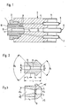
- FIG. 1 shows a burner in which a nozzle 1 is fastened to a nozzle holder 3 by means of a nozzle screw 2.
- a shaft tube 5 and a heating gas feed tube 6, a heating oxygen feed tube 7 and a cutting oxygen feed tube 8 are soldered into the nozzle receptacle 4.
- Heating mixture bores 10 lead from ring channels 9, which are formed between the nozzle holder 3 or 4 and the nozzle 2, to and from the nozzle outlet give a cutting oxygen nozzle bore 11 with its cutting oxygen outlet bore 12.
- the cutting oxygen enters the nozzle bore 11 from the shaft tube 8 via a cutting oxygen inlet bore 13.
- the length 1 D of the nozzle bore 11 has been significantly shortened and at the same time the diameter d A of the outlet bore 12 significantly enlarged.
- the pressure loss in the nozzle bore could be greatly reduced, which in turn was only possible if the transition 14 from the inlet bore 13 of the nozzle bore 11 was designed in such a way that only a small outlet distance in the nozzle bore 11 was required.
- the transition 14 from the inlet bore 13 to the nozzle bore 11 consists of a sharp-edged corner 14 and, taking into account the dependence on pressure, nozzle bore diameter d D and nozzle bore length 1 D, can be rounded slightly to avoid a maximum impact loss.
- the cylindrically shaped nozzle bore 11 for the cutting oxygen jet is to be provided with a short, not greater than 10 mm to zero, length, preferably a length of 0.5 to 5 mm.
- a comparatively small diameter of 4 mm or less is to be provided, with 1.5 mm to 3.6 mm being the preferred range.
- the outlet bore adjoining on the outlet side should have a final outlet diameter of 6 mm or less, preferably 3 to 5.4 mm. Good results were achieved with a nozzle whose nozzle bore diameter was 1.8 mm with an outlet diameter of 3.3 mm and a further nozzle with a nozzle bore diameter of 2.8 mm and an outlet diameter of 4.8 mm. Further advantageous dimensions are specified in the characterizing part of subclaims 15, 16, 17 and 18.
- the holes are cylindrical, apart from chamfers, rounded edges, drill angles and sealing surfaces.
- a cone angle of approximately ⁇ A occurs through the smoothing tool between the outlet bore 12 and the nozzle bore 11 and a drill angle or chamfer ⁇ E at the transition from the inlet bore to the nozzle bore.
- the outlet bore may have a slight conical widening ⁇ A. 3 shows, the cone of the outlet bore 12 leaves only a small length of the nozzle bore 11, the inlet bore 13 tapering at 15. It is also possible that the cone of the outlet bore 11 attaches directly to the bottom of the inlet bore 13 having a larger diameter or that the nozzle bore 11 has a somewhat longer length than is shown in FIG. 3.
- the nozzle shown in FIG. 3 is practically composed of the cylinder and truncated cone of the inlet bore 13, the short cylinder bore 11 and the inverted truncated cone of the outlet bore 12.
- the manufacture requires three work steps: Either firstly the cylindrical hole d D is drilled, secondly the inlet hole d E is drilled and thirdly the outlet hole d A is drilled and the cone is reamed, or firstly the inlet hole d E is drilled and secondly the nozzle hole d D then drilled out and thirdly the cone d A preferably rubbed between 6 and 8 °.
- the length of the outlet cone with diameter depends on the pressure and quantity ratios.
- the ratio of the nozzle diameter to the nozzle exit edge is preferably in the range from 0.5 to 0.8, or there were favorable values with a ratio of the cross sections of the nozzle bore to the nozzle exit cross section in the range from 0.3 to 0.35 .
- a cutting speed of 180 to 210 or 150 to 250 mm / min could be achieved at an oxygen working pressure of 16 to 20 or 7 to 7 bar, with a kerf of no more than 6 to 7 mm or 6, 5 to 9 mm resulted.
- the length of the nozzle bore was 3.25 or 0.65 mm with a bore diameter of 1.8 or 2.6 mm.
- Fig. 4 shows the adaptation of the short nozzle shape to a long nozzle.
- the diameter d E of the inlet bore 13 is substantially larger than the diameter dD of the nozzle bore 11. In this way, practically no pressure loss is achieved through the inlet bore 13.
- FIG. 5 shows a further development of the invention.
- An outer shaft tube 23 and an inner shaft tube 24 are soldered to the nozzle 22.
- the chamber 25 surrounded by the inner shaft tube 24 is provided with an oxygen supply connector 26, while the intermediate space 27, that of the outer shaft tube 23 and the inner shaft tube 24 arranged concentrically at a distance from one another is formed, is provided with a gas supply nozzle 28. From the space 27 lead to the heating gas bores 29 connecting channels 30, and the heating gas bores 29 are also connected by connecting channels 31 to the oxygen chamber 25, so that a mixture of heating gas and heating oxygen is supplied to the bores 29.
- the oxygen chamber 25 runs in accordance with the previously described Nozzle form a cutting oxygen nozzle bore 32 which opens into the cutting oxygen outlet bore 33. In this way, a burner is made available which consists of a uniform nozzle part with an integrated holding part with connections.
- the invention can also be useful for nozzles that are screwed in directly.
- the shorter nozzle part is provided with a thread for screwing into the holding part below the sealing head and with key surfaces on the foot near the outlet.
- the threaded nozzle part or a nozzle screw with an attached guide can be provided for secure attachment and thus easier screwing in, the initial nut thread being interrupted in two areas on the circumference and the screw thread begins sharply at the nozzle part.
- markings on the nozzle part and holding part can be provided.
Landscapes
- Engineering & Computer Science (AREA)
- Chemical & Material Sciences (AREA)
- Combustion & Propulsion (AREA)
- Mechanical Engineering (AREA)
- General Engineering & Computer Science (AREA)
- Gas Burners (AREA)
- Processing Of Solid Wastes (AREA)
- Manufacture And Refinement Of Metals (AREA)
- Solid-Sorbent Or Filter-Aiding Compositions (AREA)
Priority Applications (1)
| Application Number | Priority Date | Filing Date | Title |
|---|---|---|---|
| AT82104845T ATE25760T1 (de) | 1981-06-05 | 1982-06-03 | Brenner zum thermochemischen trennen und/oder abholen von werkstuecken aus stahl. |
Applications Claiming Priority (2)
| Application Number | Priority Date | Filing Date | Title |
|---|---|---|---|
| DE19813122404 DE3122404A1 (de) | 1981-06-05 | 1981-06-05 | Brenner zum thermochemischen brennen und/oder abhobeln von werkstuecken aus stahl |
| DE3122404 | 1981-06-05 |
Publications (4)
| Publication Number | Publication Date |
|---|---|
| EP0068165A2 true EP0068165A2 (fr) | 1983-01-05 |
| EP0068165A3 EP0068165A3 (en) | 1983-09-07 |
| EP0068165B1 EP0068165B1 (fr) | 1987-03-04 |
| EP0068165B2 EP0068165B2 (fr) | 1994-09-28 |
Family
ID=6134032
Family Applications (1)
| Application Number | Title | Priority Date | Filing Date |
|---|---|---|---|
| EP82104845A Expired - Lifetime EP0068165B2 (fr) | 1981-06-05 | 1982-06-03 | Brûleur pour découper et/ou dégrossir thermochimiquement des pièces à usiner en acier |
Country Status (3)
| Country | Link |
|---|---|
| EP (1) | EP0068165B2 (fr) |
| AT (1) | ATE25760T1 (fr) |
| DE (2) | DE3122404A1 (fr) |
Cited By (4)
| Publication number | Priority date | Publication date | Assignee | Title |
|---|---|---|---|---|
| EP0780184A1 (fr) * | 1995-12-20 | 1997-06-25 | AUTE AG Gesellschaft für autogene Technik | Dispositif pour couper longitudinalement et transversalement des brames d'acier chaudes ou froides |
| EP1632303A1 (fr) * | 2004-09-02 | 2006-03-08 | Aute AG Gesellschaft für autogene Technik | Chalumeau de découpage de pièces en acier chaud ou froid ayant une meilleure séparation rapide et douce de l'oxygène avec une maintenance et une utilisation de l'oxygène sous pression améliorées |
| EP3059497A2 (fr) * | 2015-02-18 | 2016-08-24 | Delavan, Inc. | Mélange turbulent amélioré |
| CN107116479A (zh) * | 2017-05-15 | 2017-09-01 | 四川大学 | 用于光学元件加工的数控湿法化学刻蚀组合喷嘴 |
Families Citing this family (1)
| Publication number | Priority date | Publication date | Assignee | Title |
|---|---|---|---|---|
| EP0097883B1 (fr) * | 1982-06-26 | 1987-09-16 | AUTE Gesellschaft für autogene Technik mbH | Tuyère courte en une seule pièce pour un brûleur pour le coupage ou le rabotage thermo-chimique |
Family Cites Families (3)
| Publication number | Priority date | Publication date | Assignee | Title |
|---|---|---|---|---|
| AU417614B2 (en) * | 1967-03-22 | 1971-10-01 | Iwatani & Company Limited | Flame cutting method and apparatus |
| JPS5236107B2 (fr) * | 1971-10-27 | 1977-09-13 | ||
| GB1497793A (en) * | 1974-10-24 | 1978-01-12 | Boc International Ltd | Cutting nozzles |
-
1981
- 1981-06-05 DE DE19813122404 patent/DE3122404A1/de not_active Withdrawn
-
1982
- 1982-06-03 AT AT82104845T patent/ATE25760T1/de not_active IP Right Cessation
- 1982-06-03 EP EP82104845A patent/EP0068165B2/fr not_active Expired - Lifetime
- 1982-06-03 DE DE8282104845T patent/DE3275582D1/de not_active Expired
Cited By (6)
| Publication number | Priority date | Publication date | Assignee | Title |
|---|---|---|---|---|
| EP0780184A1 (fr) * | 1995-12-20 | 1997-06-25 | AUTE AG Gesellschaft für autogene Technik | Dispositif pour couper longitudinalement et transversalement des brames d'acier chaudes ou froides |
| AU721006B2 (en) * | 1995-12-20 | 2000-06-22 | Aute Ag | Continuous steel casting plant with following cross-cutting and slitting equipment for oxytorch cutting of hot and cold strands |
| EP1632303A1 (fr) * | 2004-09-02 | 2006-03-08 | Aute AG Gesellschaft für autogene Technik | Chalumeau de découpage de pièces en acier chaud ou froid ayant une meilleure séparation rapide et douce de l'oxygène avec une maintenance et une utilisation de l'oxygène sous pression améliorées |
| EP3059497A2 (fr) * | 2015-02-18 | 2016-08-24 | Delavan, Inc. | Mélange turbulent amélioré |
| CN107116479A (zh) * | 2017-05-15 | 2017-09-01 | 四川大学 | 用于光学元件加工的数控湿法化学刻蚀组合喷嘴 |
| CN107116479B (zh) * | 2017-05-15 | 2018-11-20 | 四川大学 | 用于光学元件加工的数控湿法化学刻蚀组合喷嘴 |
Also Published As
| Publication number | Publication date |
|---|---|
| DE3122404A1 (de) | 1983-01-05 |
| EP0068165B1 (fr) | 1987-03-04 |
| EP0068165A3 (en) | 1983-09-07 |
| DE3275582D1 (en) | 1987-04-09 |
| EP0068165B2 (fr) | 1994-09-28 |
| ATE25760T1 (de) | 1987-03-15 |
Similar Documents
| Publication | Publication Date | Title |
|---|---|---|
| EP3291941B1 (fr) | Buse à gaz de découpe et procédé de découpe au laser faisant appel à une douille coulissante pour régler la caractéristique d'écoulement | |
| DE2130394A1 (de) | Lichtbogenschneidverfahren | |
| EP1407848B1 (fr) | Outil de filetage avec refroidissement | |
| EP0097883B1 (fr) | Tuyère courte en une seule pièce pour un brûleur pour le coupage ou le rabotage thermo-chimique | |
| EP2219813A1 (fr) | Palier aérostatique et procédé de fabrication | |
| DE3321697C2 (fr) | ||
| DE2633719A1 (de) | Verfahren zum betreiben eines schneidbrenners | |
| EP0068165B1 (fr) | Brûleur pour découper et/ou dégrossir thermochimiquement des pièces à usiner en acier | |
| DE2452004A1 (de) | Duese zum schweissen, heizen, schneiden und/oder flaemmen | |
| DE3629033C2 (fr) | ||
| DE19754518C2 (de) | Kombination aus Gewindebohrer oder -former und dazugehöriger Adapterhülse für die Minimalmengenschmierung | |
| DE3630127C2 (fr) | ||
| DE102013106511B4 (de) | Düse zum Schneiden von Stahlwerkstücken | |
| DE1552320A1 (de) | Bohrwerkzeug | |
| DE2046415A1 (de) | Brenner zur thermochemischen Bearbei tung von Werkstucken | |
| DE4429069C2 (de) | Lötbrenner | |
| DE2046414C3 (de) | Schneidbrenner | |
| WO2009030431A2 (fr) | Tête d'usinage au laser pour usiner une pièce au moyen d'un faisceau laser | |
| DE1529194C (de) | Schweißbrennereinsatz | |
| WO2005105351A1 (fr) | Interface pour outil de coupe | |
| DE2151294C3 (de) | Brennermundstück | |
| DE2364556C3 (de) | AuBenmischende Brennschneiddüse | |
| DE3810620C1 (en) | Plasma burner | |
| DE29618293U1 (de) | Bohrer für Platten aus Natur- oder Kunststein | |
| DD255437A7 (de) | Zusammengesetzte duese fuer ein plasmatron |
Legal Events
| Date | Code | Title | Description |
|---|---|---|---|
| PUAI | Public reference made under article 153(3) epc to a published international application that has entered the european phase |
Free format text: ORIGINAL CODE: 0009012 |
|
| AK | Designated contracting states |
Designated state(s): AT BE CH DE FR GB LI |
|
| PUAL | Search report despatched |
Free format text: ORIGINAL CODE: 0009013 |
|
| AK | Designated contracting states |
Designated state(s): AT BE CH DE FR GB LI |
|
| 17P | Request for examination filed |
Effective date: 19831220 |
|
| GRAA | (expected) grant |
Free format text: ORIGINAL CODE: 0009210 |
|
| AK | Designated contracting states |
Kind code of ref document: B1 Designated state(s): AT BE CH DE FR GB LI |
|
| REF | Corresponds to: |
Ref document number: 25760 Country of ref document: AT Date of ref document: 19870315 Kind code of ref document: T |
|
| REF | Corresponds to: |
Ref document number: 3275582 Country of ref document: DE Date of ref document: 19870409 |
|
| ET | Fr: translation filed | ||
| PLBI | Opposition filed |
Free format text: ORIGINAL CODE: 0009260 |
|
| 26 | Opposition filed |
Opponent name: MESSER GRIESHEIM GMBH Effective date: 19871202 |
|
| RAP2 | Party data changed (patent owner data changed or rights of a patent transferred) |
Owner name: AUTE AG GESELLSCHAFT FUER AUTOGENE TECHNIK |
|
| REG | Reference to a national code |
Ref country code: CH Ref legal event code: PFA Free format text: AUTE AG GESELLSCHAFT FUER AUTOGENE TECHNIK |
|
| BECA | Be: change of holder's address |
Free format text: 911009 *AUTE AG -G. FUR AUTOGENE TECHNIK:10 RUE SAINT-HONORE, 2000 NEUCHTEL |
|
| REG | Reference to a national code |
Ref country code: FR Ref legal event code: TP |
|
| PGFP | Annual fee paid to national office [announced via postgrant information from national office to epo] |
Ref country code: AT Payment date: 19920615 Year of fee payment: 11 |
|
| PG25 | Lapsed in a contracting state [announced via postgrant information from national office to epo] |
Ref country code: AT Effective date: 19930603 |
|
| PGFP | Annual fee paid to national office [announced via postgrant information from national office to epo] |
Ref country code: CH Payment date: 19930630 Year of fee payment: 12 |
|
| PG25 | Lapsed in a contracting state [announced via postgrant information from national office to epo] |
Ref country code: LI Effective date: 19940630 Ref country code: CH Effective date: 19940630 |
|
| PUAA | Information related to the publication of a b2 document modified |
Free format text: ORIGINAL CODE: 0009299PMAP |
|
| PUAH | Patent maintained in amended form |
Free format text: ORIGINAL CODE: 0009272 |
|
| STAA | Information on the status of an ep patent application or granted ep patent |
Free format text: STATUS: PATENT MAINTAINED AS AMENDED |
|
| 27A | Patent maintained in amended form |
Effective date: 19940928 |
|
| AK | Designated contracting states |
Kind code of ref document: B2 Designated state(s): GB |
|
| R27A | Patent maintained in amended form (corrected) |
Effective date: 19940928 |
|
| REG | Reference to a national code |
Ref country code: CH Ref legal event code: AEN |
|
| ET3 | Fr: translation filed ** decision concerning opposition | ||
| REG | Reference to a national code |
Ref country code: CH Ref legal event code: PL |
|
| PGFP | Annual fee paid to national office [announced via postgrant information from national office to epo] |
Ref country code: GB Payment date: 19960530 Year of fee payment: 15 |
|
| PGFP | Annual fee paid to national office [announced via postgrant information from national office to epo] |
Ref country code: FR Payment date: 19960628 Year of fee payment: 15 |
|
| PGFP | Annual fee paid to national office [announced via postgrant information from national office to epo] |
Ref country code: BE Payment date: 19960730 Year of fee payment: 15 |
|
| PGFP | Annual fee paid to national office [announced via postgrant information from national office to epo] |
Ref country code: DE Payment date: 19960828 Year of fee payment: 15 |
|
| PG25 | Lapsed in a contracting state [announced via postgrant information from national office to epo] |
Ref country code: GB Effective date: 19970603 |
|
| PG25 | Lapsed in a contracting state [announced via postgrant information from national office to epo] |
Ref country code: BE Effective date: 19970630 |
|
| BERE | Be: lapsed |
Owner name: AUTE AG -G. FUR AUTOGENE TECHNIK Effective date: 19970630 |
|
| GBPC | Gb: european patent ceased through non-payment of renewal fee |
Effective date: 19970603 |
|
| PG25 | Lapsed in a contracting state [announced via postgrant information from national office to epo] |
Ref country code: FR Free format text: LAPSE BECAUSE OF NON-PAYMENT OF DUE FEES Effective date: 19980227 |
|
| PG25 | Lapsed in a contracting state [announced via postgrant information from national office to epo] |
Ref country code: DE Free format text: LAPSE BECAUSE OF NON-PAYMENT OF DUE FEES Effective date: 19980303 |
|
| REG | Reference to a national code |
Ref country code: FR Ref legal event code: ST |
|
| REG | Reference to a national code |
Ref country code: FR Ref legal event code: ST |