EP0068175A1 - Fibre optique pour transporter des images - Google Patents
Fibre optique pour transporter des images Download PDFInfo
- Publication number
- EP0068175A1 EP0068175A1 EP82104931A EP82104931A EP0068175A1 EP 0068175 A1 EP0068175 A1 EP 0068175A1 EP 82104931 A EP82104931 A EP 82104931A EP 82104931 A EP82104931 A EP 82104931A EP 0068175 A1 EP0068175 A1 EP 0068175A1
- Authority
- EP
- European Patent Office
- Prior art keywords
- transmission path
- image
- core
- light
- image transmission
- Prior art date
- Legal status (The legal status is an assumption and is not a legal conclusion. Google has not performed a legal analysis and makes no representation as to the accuracy of the status listed.)
- Granted
Links
- 239000000835 fiber Substances 0.000 title claims abstract description 44
- 230000005540 biological transmission Effects 0.000 claims abstract description 52
- 239000013307 optical fiber Substances 0.000 claims abstract description 28
- 238000005253 cladding Methods 0.000 claims abstract description 23
- 239000000463 material Substances 0.000 claims description 21
- 239000012790 adhesive layer Substances 0.000 claims description 13
- 238000000034 method Methods 0.000 claims description 8
- 230000005855 radiation Effects 0.000 claims description 8
- 206010073306 Exposure to radiation Diseases 0.000 claims description 4
- 239000000203 mixture Substances 0.000 claims description 3
- 238000010438 heat treatment Methods 0.000 claims description 2
- 239000010410 layer Substances 0.000 claims description 2
- 230000001678 irradiating effect Effects 0.000 claims 1
- 239000000155 melt Substances 0.000 claims 1
- 239000000853 adhesive Substances 0.000 description 6
- 230000001070 adhesive effect Effects 0.000 description 6
- 239000006096 absorbing agent Substances 0.000 description 4
- 239000011521 glass Substances 0.000 description 3
- 230000007547 defect Effects 0.000 description 2
- 230000008030 elimination Effects 0.000 description 2
- 238000003379 elimination reaction Methods 0.000 description 2
- 239000003822 epoxy resin Substances 0.000 description 2
- 230000000873 masking effect Effects 0.000 description 2
- 239000002184 metal Substances 0.000 description 2
- 229920000647 polyepoxide Polymers 0.000 description 2
- VYPSYNLAJGMNEJ-UHFFFAOYSA-N Silicium dioxide Chemical compound O=[Si]=O VYPSYNLAJGMNEJ-UHFFFAOYSA-N 0.000 description 1
- 239000000919 ceramic Substances 0.000 description 1
- 230000003247 decreasing effect Effects 0.000 description 1
- 238000010586 diagram Methods 0.000 description 1
- 238000009792 diffusion process Methods 0.000 description 1
- 238000005530 etching Methods 0.000 description 1
- 239000005308 flint glass Substances 0.000 description 1
- 238000005286 illumination Methods 0.000 description 1
- 238000003384 imaging method Methods 0.000 description 1
- 230000031700 light absorption Effects 0.000 description 1
- 238000004519 manufacturing process Methods 0.000 description 1
- 238000005259 measurement Methods 0.000 description 1
- 230000003287 optical effect Effects 0.000 description 1
- 238000003909 pattern recognition Methods 0.000 description 1
- 230000000704 physical effect Effects 0.000 description 1
- 238000002360 preparation method Methods 0.000 description 1
- 238000005204 segregation Methods 0.000 description 1
- 239000000126 substance Substances 0.000 description 1
Images

Classifications
-
- G—PHYSICS
- G02—OPTICS
- G02B—OPTICAL ELEMENTS, SYSTEMS OR APPARATUS
- G02B6/00—Light guides; Structural details of arrangements comprising light guides and other optical elements, e.g. couplings
- G02B6/04—Light guides; Structural details of arrangements comprising light guides and other optical elements, e.g. couplings formed by bundles of fibres
- G02B6/06—Light guides; Structural details of arrangements comprising light guides and other optical elements, e.g. couplings formed by bundles of fibres the relative position of the fibres being the same at both ends, e.g. for transporting images
Definitions
- the present invention relates to an improved fiber optics image transmission path, and more particularly to a fiber optics image transmission path capable of transmitting a high-contrast image and other information.
- One prior art image transmission path is formed of individual optical fibers bundled together in side-by-side relation, each fiber serving as a picture element and consisting of a core having a higher refractive index and a surrounding cladding having a lower refractive index.
- An enlarged view of the transmission end of this type of image transmission path is shown in Fig. 1, wherein an individual optical fiber 1 consists of a core 2 and cladding 3. Due to the difference in refractive index between the core and cladding, light A input to the core is totally reflected a great many times at the interface between the core and cladding before reaching the receiving end of the fiber. But light B impinging upon the cladding becomes a leaky mode, and as it is reflected or scattered at various interfaces in the interior of the transmission path, it is carried over to the receiving end as noise light C, providing only a low- contrast image at that end.
- the cladding that insulates two adjacent optical fibers is usually made of a glass material-having fairly high light transmissivity, so crosstalk sometimes occurs between the fibers. If the diameter of each fiber and the distance between adjacent fibers are as small as the wavelength of the light, a significantly large energy is transmitted by the light that travels. outside the fibers. The occurrence of crosstalk becomes more conspicuous as the difference in refractive index between the core and cladding is decreased, and this gain reduces the contrast of the image transmitted to the receiving end.
- a first object of the present invention is to provide a means for achieving this parameter, i.e. the substantial elimination of crosstalk between cores.
- a further object of the present invention is to provide an image transmission path that uses the above property to advantage in transmitting a high-contrast sharp image.
- Still another object of the present invention is to provide an image transmitting path that is free from this defect and is capable transmitting a high-contrast image.
- an image fiber is produced by forming a bundle of optical fibers made of a glassy or vitreous material which is optically stable against radiation, filling the gap between individual fibers with a glassy material that easily changes its color upon exposure to radiation, and illuminating the resulting image fiber device with radiation to cause a color change in the glassy material between the fibers to thereby form a light absorbing section.
- the image fiber device is shown in Fig. 2, wherein the reference numeral 4 indicates an optical fiber, 5 is the core, .6 is the cladding and 7 is the light absorbing section.
- the core 5 and cladding 6 of the optical fiber 4 are generally made of glassy material such as quartz glass which is optically stable against radiation.
- the optical fiber 4 has a relatively large diameter.
- the light absorbing section 7 is made of a glassy material such as dense flint glass or germanium-doped glass that easily changes its color upon exposure to radiation. These materials have high refractive index, whidh further increases the effectiveness of the light absorbing section formed of these materials.
- the image fiber device of the present invention is produced by the following method.
- a number of fine wires or fibers of a glassy material that easily changes its color upon exposure to radiation are intermingled with a number of coarse optical fibers 4, and the blend is put in a glass tube that later serves as a jacket and is drawn with heat to a given length of image fiber device, in which the molten wires or fibers of the glassy material completely fill the gaps between individual fibers 4.
- Both the optical fibers 4 and the encircling absorber 7 are made of a glassy mateiial and have similar chemical and physical properties, so only a minimum strain develops during the manufacturing process (heating, growing and drawing), and hence there is little chance of damage or segregation among the optical fibers.
- the image fiber device is then exposed to radiation, say, gamma-rays, to cause a color change in the glassy material between the optical fibers 4 to thereby form a light absorbing section 7.
- the degree of the change in color of the absorber 7 can be varied by controlling the amount of the radiation to which the image fiber device is exposed.
- the color changing glassy material is provided between the optical fibers 4 by intermingling them with the glassy material in the form of fine wire or fibers, but it is to be understood that any other suitable method can be used to achieve the stated objective.
- the thus prepared image fiber device of the present invention has a light absorbing section between individual optical fibers and this absorbing section achieves a precise and desired absorption of light necessary for transmitting a high- constrast image to the receiving end.
- the present invention also encompasses an image transmission path formed of individual optical fibers, each consisting of a core having a higher refractive index and a claddding having a lower refractive index and which are bundled together in side-by-side relation, characterized in that a connector is linked to one or both ends of the image transmission path by means of an adhesive that has a higher refractive index and higher transmission loss than the cladding.
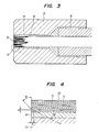
- Fig. 3 is a longitudinal sectional view showing the structure of one connected end of an image transmission path designed to meet the stated objects of the present invention.
- Fig. 4 is an enlarged geometric view of a portion II of Fig. 3 indicated by the dash line.
- An image fiber device 9 at an end where it is uncovered from its sheath 8 is formed of a bundle of aligned optical fibers 12 each consisting .of a core 10 for transmitting.light and a surrounding cladding 11 having a lower - refractive index than the core.
- the connected end of the image fiber device 9 is fitted into a cylindrical connector 13 made of ceramics or metal.
- the gap between the connector 13 and the image fiber device 9 is filled with an adhesive 14 that integrally binds the two.
- the adhesive must have.a higher refractive index as well as a higher transmission loss than the cladding 11.
- the adhesive 14 may be made of a black epoxy resin or an epoxy resin loaded with india ink, but it is to be understood that any other material may be used if it satisfies the above two stated requirements.
- the adhesive 14 forms a layer that serves as a light absorber. It has a higher refractive index than the cladding 11 so that any crosstalk that develops at the interface of the outermost optical fibers 12 and the adhesive layer 14 enters the adhesive layer 14 rather than the adjacent fiber.
- the adhesive layer also has high transmission loss so that the crosstalk may not reflect from the interface of the adhesive layer 14 and the connector 13 to undesirably re-enter the optical fiber 12. Therefore, any crosstalk will be absorbed by the adhesive layer 14 as light is transmitted along the image transmission path. It will be . apparent to those skilled in the art that if the image fiber device 9 is covered with a jacket, the adhesive layer 14 must have a higher refractive index than the jacket.
- the image transmission path-of the present invention has an adhesive layer that has a higher refractive index than the cladding of each optical fiber and which hence serves as a light absorber that directs any crosstalk to the exterior of the transmission path.
- the image transmittion path of the present invention is capable fo transmitting a significantly high-contrast image to the receiving end.
- the first object of the present invention can be acheived by an image tranmission path comprising optical fibers bundled : together in side-by-side relation, characterized by the placement of a mask member in front of the sending end of the transmission path, the mask member being enlarged in size in comparison with the sending end of the transmission path and having a lower light transmissivity in that area corresponding to the area of the sending end of the transmission path that makes no contribution to image transmission.
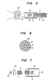
- That area of the mask which is indicated by 19 represents a plurality of light-transmitting areas that are arranged in pattern corresponding to the core array of the optical fibers 9 on the tranmission side.
- Fig. 5 further includes an imaging lens system 20 that is positioned in front of the mask 16 to project the incident light toward the mask. The light incident on the mask 16 is projected onto the sending end of the image transmission path I by a mask projecting lens system 21 provided in the adapter 15.
- any incident light that would enter the cladding is absorbed by the non-transmitting area 18 of the mask 16, and only the incident light that would enter the cores passes through the transmitting area 19 and is projected by the lens system 21 onto the core array of the sending end 17.
- a photographic film 16' is attached to the tip of the mask adapter 15 connected to one end of the image transmission path I which includes the mask projecting lens system 21.
- the film has at least one notch 22 for ensuring good matching with the mask adapter 15, and the mask adapter has a corresponding projection at the end thereof.
- a light source 24. is placed at the back of the image transmission path I, with a diffusion: plate 23 placed inbetween.
- the fiber array 9. is then projected on the sending end of the transmission path I onto the film 16' through the lens system 21.
- the film is then removed and printed to a hard tone and converted to either a positive or negative mask 16.
- the thus prepared mask has a light-transmitting area 19 in the area that corresponds to the core array of the optical fibers 9, and a non-transmitting area 18 having low light transmissivity in the area corresponding to the cladding array.
- the mask 16 is then attached to the end of the mask adapter 15 by matching the notch 22 with the projection on the adapter. It is to be understood that the mask 16 can be prepared by any other suitable method, such as by etching a thin metal film.
- the present invention can be applied to general types of image transmission paths and to devices such as endoscopes and gastroscopes which use such an image transmission path.
- the image transmission-path of the present invention eliminates the possibility of light falling on the cladding, so it is capable of transmitting an image of improved consrast. This result can be achieved by simply making a mask according to the present invention and attaching it to a conventional image transmission path together with a.lens system.
- the image transmission path of the present invention can be fabricated more easily than the prior art system using the direct masking method.
Landscapes
- Physics & Mathematics (AREA)
- General Physics & Mathematics (AREA)
- Optics & Photonics (AREA)
- Optical Fibers, Optical Fiber Cores, And Optical Fiber Bundles (AREA)
- Glass Compositions (AREA)
Priority Applications (3)
| Application Number | Priority Date | Filing Date | Title |
|---|---|---|---|
| DE8282104931T DE3270844D1 (en) | 1981-06-18 | 1982-06-04 | Image conducting fiber device |
| DE8484108135T DE3277707D1 (en) | 1981-06-18 | 1982-06-04 | Image transmission device |
| DE8484108136T DE3278142D1 (en) | 1981-06-18 | 1982-06-04 | Image transmission path |
Applications Claiming Priority (6)
| Application Number | Priority Date | Filing Date | Title |
|---|---|---|---|
| JP56092966A JPS57208511A (en) | 1981-06-18 | 1981-06-18 | Manufacture of bundled fiber |
| JP92966/81 | 1981-06-18 | ||
| JP116053/81 | 1981-07-24 | ||
| JP56116053A JPS5817403A (ja) | 1981-07-24 | 1981-07-24 | 画像伝送路 |
| JP56119279A JPS5821209A (ja) | 1981-07-31 | 1981-07-31 | 画像伝送路 |
| JP119279/81 | 1981-07-31 |
Related Parent Applications (1)
| Application Number | Title | Priority Date | Filing Date |
|---|---|---|---|
| EP82104931.9 Division | 1982-06-04 |
Related Child Applications (3)
| Application Number | Title | Priority Date | Filing Date |
|---|---|---|---|
| EP84108136.7 Division-Into | 1982-06-04 | ||
| EP82104931.9 Division-Into | 1982-06-04 | ||
| EP84108135.9 Division-Into | 1982-06-04 |
Publications (2)
| Publication Number | Publication Date |
|---|---|
| EP0068175A1 true EP0068175A1 (fr) | 1983-01-05 |
| EP0068175B1 EP0068175B1 (fr) | 1986-04-30 |
Family
ID=27307161
Family Applications (1)
| Application Number | Title | Priority Date | Filing Date |
|---|---|---|---|
| EP82104931A Expired EP0068175B1 (fr) | 1981-06-18 | 1982-06-04 | Fibre optique pour transporter des images |
Country Status (3)
| Country | Link |
|---|---|
| EP (1) | EP0068175B1 (fr) |
| AU (1) | AU552089B2 (fr) |
| CA (1) | CA1209090A (fr) |
Cited By (6)
| Publication number | Priority date | Publication date | Assignee | Title |
|---|---|---|---|---|
| WO1984004821A1 (fr) * | 1983-05-24 | 1984-12-06 | Incom Inc | Filtre de lumiere |
| DE3724749A1 (de) * | 1986-07-29 | 1988-02-11 | Mitsubishi Cable Ind Ltd | Faseroptischer leiter und diesen verwendendes bildsichtgeraet |
| EP0417856A1 (fr) * | 1989-09-14 | 1991-03-20 | Koninklijke Philips Electronics N.V. | Dispositif pour explorer un document par voie optique |
| EP0476596A1 (fr) * | 1990-09-18 | 1992-03-25 | Kabushiki Kaisha Toshiba | Connecteur du guide de lumière |
| GB2275348A (en) * | 1993-02-20 | 1994-08-24 | Secr Defence | Optical fibre probe |
| CN115353284A (zh) * | 2022-09-09 | 2022-11-18 | 中国建筑材料科学研究总院有限公司 | 一种高对比度光纤传像元件及其制备方法 |
Citations (4)
| Publication number | Priority date | Publication date | Assignee | Title |
|---|---|---|---|---|
| US3436142A (en) * | 1965-05-17 | 1969-04-01 | American Optical Corp | Fiber optical image-conducting devices embodying varying controlled stray light absorbing means |
| GB1219597A (en) * | 1968-11-29 | 1971-01-20 | Mullard Ltd | Improvements in or relating to fibre-optic devices |
| US3797910A (en) * | 1971-09-14 | 1974-03-19 | Corning Glass Works | Fiber optic device having some fibers clad with absorbing glasses |
| US4153333A (en) * | 1976-02-23 | 1979-05-08 | Fuji Photo Optical Co., Ltd. | Optical fiber bundle with field stop |
-
1982
- 1982-06-04 EP EP82104931A patent/EP0068175B1/fr not_active Expired
- 1982-06-16 CA CA000405330A patent/CA1209090A/fr not_active Expired
- 1982-06-18 AU AU84981/82A patent/AU552089B2/en not_active Ceased
Patent Citations (4)
| Publication number | Priority date | Publication date | Assignee | Title |
|---|---|---|---|---|
| US3436142A (en) * | 1965-05-17 | 1969-04-01 | American Optical Corp | Fiber optical image-conducting devices embodying varying controlled stray light absorbing means |
| GB1219597A (en) * | 1968-11-29 | 1971-01-20 | Mullard Ltd | Improvements in or relating to fibre-optic devices |
| US3797910A (en) * | 1971-09-14 | 1974-03-19 | Corning Glass Works | Fiber optic device having some fibers clad with absorbing glasses |
| US4153333A (en) * | 1976-02-23 | 1979-05-08 | Fuji Photo Optical Co., Ltd. | Optical fiber bundle with field stop |
Non-Patent Citations (1)
| Title |
|---|
| IBM TECHNICAL DISCLOSURE BULLETIN, vol.22, no.1, June 1979, * |
Cited By (9)
| Publication number | Priority date | Publication date | Assignee | Title |
|---|---|---|---|---|
| WO1984004821A1 (fr) * | 1983-05-24 | 1984-12-06 | Incom Inc | Filtre de lumiere |
| DE3724749A1 (de) * | 1986-07-29 | 1988-02-11 | Mitsubishi Cable Ind Ltd | Faseroptischer leiter und diesen verwendendes bildsichtgeraet |
| US4783135A (en) * | 1986-07-29 | 1988-11-08 | Mitsubishi Cable Industries, Ltd. | Optical fiber conductor and image scope using same |
| EP0417856A1 (fr) * | 1989-09-14 | 1991-03-20 | Koninklijke Philips Electronics N.V. | Dispositif pour explorer un document par voie optique |
| EP0476596A1 (fr) * | 1990-09-18 | 1992-03-25 | Kabushiki Kaisha Toshiba | Connecteur du guide de lumière |
| US5297226A (en) * | 1990-09-18 | 1994-03-22 | Kabushiki Kaisha Toshiba | Light guide connector |
| GB2275348A (en) * | 1993-02-20 | 1994-08-24 | Secr Defence | Optical fibre probe |
| GB2275348B (en) * | 1993-02-20 | 1996-06-19 | Secr Defence | Optical sensors |
| CN115353284A (zh) * | 2022-09-09 | 2022-11-18 | 中国建筑材料科学研究总院有限公司 | 一种高对比度光纤传像元件及其制备方法 |
Also Published As
| Publication number | Publication date |
|---|---|
| AU8498182A (en) | 1982-12-23 |
| CA1209090A (fr) | 1986-08-05 |
| AU552089B2 (en) | 1986-05-22 |
| EP0068175B1 (fr) | 1986-04-30 |
Similar Documents
| Publication | Publication Date | Title |
|---|---|---|
| US4483585A (en) | Illuminating device having optical light guide formed as fibre bundle | |
| JP3079969B2 (ja) | 完全密着型イメージセンサ及びその製造方法 | |
| US3658407A (en) | Image transmitter formed of a plurality of graded index fibers in bundled configuration | |
| EP0100517B1 (fr) | Capteur à fibres optiques | |
| US3253500A (en) | Doubly clad light-conducting fibers with the outer cladding being partially light absorbing | |
| US4137060A (en) | Method of forming a lens at the end of a light guide | |
| US4193663A (en) | Coupling-equipped light guide | |
| US4615583A (en) | Image fibers | |
| JP5259096B2 (ja) | ファイバオプティック及びその製造方法 | |
| GB1574355A (en) | Optical fibres | |
| GB2112166A (en) | Tubular light transmitting element | |
| GB2033889A (en) | Method for producing fibre bundles | |
| EP1454173B1 (fr) | Focalisation de fibre optique | |
| EP0729043A2 (fr) | Dispositifs de branchement optique sélectifs en longueur d'onde utilisant des réseaux à longue période | |
| EP0821248B1 (fr) | Elément à fibre optique, élément photorécepteur, et dispositif d'acquisition de structure | |
| US5297226A (en) | Light guide connector | |
| CA1051239A (fr) | Fibre ou tige photoconductrice | |
| US3397022A (en) | Optical fibers and fiber optical imagetransfer devices having light absorbing elements | |
| US5083017A (en) | X-ray image intensifier with unitary plate input phosphor screen | |
| US5319731A (en) | Fiber-optic array of limited acceptance angle | |
| US4776667A (en) | Image transmission line | |
| EP0141037B1 (fr) | Guide de transmission d'image | |
| EP0141038B1 (fr) | Guide de transmission d'image | |
| EP0068175B1 (fr) | Fibre optique pour transporter des images | |
| US6219483B1 (en) | Optical device and imaging apparatus using the same |
Legal Events
| Date | Code | Title | Description |
|---|---|---|---|
| PUAI | Public reference made under article 153(3) epc to a published international application that has entered the european phase |
Free format text: ORIGINAL CODE: 0009012 |
|
| AK | Designated contracting states |
Designated state(s): DE FR GB IT NL |
|
| 17P | Request for examination filed |
Effective date: 19830224 |
|
| GRAA | (expected) grant |
Free format text: ORIGINAL CODE: 0009210 |
|
| AC | Divisional application: reference to earlier application |
Ref document number: 68175 Country of ref document: EP |
|
| AK | Designated contracting states |
Kind code of ref document: B1 Designated state(s): DE FR GB IT NL |
|
| REF | Corresponds to: |
Ref document number: 3270844 Country of ref document: DE Date of ref document: 19860605 |
|
| ET | Fr: translation filed | ||
| ITF | It: translation for a ep patent filed | ||
| PLBE | No opposition filed within time limit |
Free format text: ORIGINAL CODE: 0009261 |
|
| STAA | Information on the status of an ep patent application or granted ep patent |
Free format text: STATUS: NO OPPOSITION FILED WITHIN TIME LIMIT |
|
| 26N | No opposition filed | ||
| ITTA | It: last paid annual fee | ||
| PGFP | Annual fee paid to national office [announced via postgrant information from national office to epo] |
Ref country code: GB Payment date: 19980526 Year of fee payment: 17 |
|
| PGFP | Annual fee paid to national office [announced via postgrant information from national office to epo] |
Ref country code: FR Payment date: 19980609 Year of fee payment: 17 |
|
| PGFP | Annual fee paid to national office [announced via postgrant information from national office to epo] |
Ref country code: DE Payment date: 19980612 Year of fee payment: 17 |
|
| PGFP | Annual fee paid to national office [announced via postgrant information from national office to epo] |
Ref country code: NL Payment date: 19980629 Year of fee payment: 17 |
|
| PG25 | Lapsed in a contracting state [announced via postgrant information from national office to epo] |
Ref country code: GB Free format text: LAPSE BECAUSE OF NON-PAYMENT OF DUE FEES Effective date: 19990604 |
|
| PG25 | Lapsed in a contracting state [announced via postgrant information from national office to epo] |
Ref country code: FR Free format text: THE PATENT HAS BEEN ANNULLED BY A DECISION OF A NATIONAL AUTHORITY Effective date: 19990630 |
|
| PG25 | Lapsed in a contracting state [announced via postgrant information from national office to epo] |
Ref country code: NL Free format text: LAPSE BECAUSE OF NON-PAYMENT OF DUE FEES Effective date: 20000101 |
|
| GBPC | Gb: european patent ceased through non-payment of renewal fee |
Effective date: 19990604 |
|
| NLV4 | Nl: lapsed or anulled due to non-payment of the annual fee |
Effective date: 20000101 |
|
| PG25 | Lapsed in a contracting state [announced via postgrant information from national office to epo] |
Ref country code: DE Free format text: LAPSE BECAUSE OF NON-PAYMENT OF DUE FEES Effective date: 20000503 |
|
| REG | Reference to a national code |
Ref country code: FR Ref legal event code: ST |