EP0068251A1 - Soupape d'inversion pour compteur compound - Google Patents
Soupape d'inversion pour compteur compound Download PDFInfo
- Publication number
- EP0068251A1 EP0068251A1 EP82105153A EP82105153A EP0068251A1 EP 0068251 A1 EP0068251 A1 EP 0068251A1 EP 82105153 A EP82105153 A EP 82105153A EP 82105153 A EP82105153 A EP 82105153A EP 0068251 A1 EP0068251 A1 EP 0068251A1
- Authority
- EP
- European Patent Office
- Prior art keywords
- ring
- valve according
- closing
- closing member
- flow
- Prior art date
- Legal status (The legal status is an assumption and is not a legal conclusion. Google has not performed a legal analysis and makes no representation as to the accuracy of the status listed.)
- Granted
Links
- 239000002131 composite material Substances 0.000 title description 2
- 238000007789 sealing Methods 0.000 claims description 22
- 230000000903 blocking effect Effects 0.000 claims description 9
- 239000007788 liquid Substances 0.000 claims description 8
- 238000006073 displacement reaction Methods 0.000 claims description 5
- 230000006835 compression Effects 0.000 claims description 3
- 238000007906 compression Methods 0.000 claims description 3
- 150000001875 compounds Chemical class 0.000 claims 1
- 230000001419 dependent effect Effects 0.000 claims 1
- 230000000694 effects Effects 0.000 description 4
- 238000011144 upstream manufacturing Methods 0.000 description 3
- 238000005259 measurement Methods 0.000 description 2
- 230000002093 peripheral effect Effects 0.000 description 2
- 238000013459 approach Methods 0.000 description 1
- 230000003247 decreasing effect Effects 0.000 description 1
- 230000008021 deposition Effects 0.000 description 1
- 239000012530 fluid Substances 0.000 description 1
- 238000011010 flushing procedure Methods 0.000 description 1
- 238000002347 injection Methods 0.000 description 1
- 239000007924 injection Substances 0.000 description 1
- 238000001746 injection moulding Methods 0.000 description 1
- 238000004519 manufacturing process Methods 0.000 description 1
- 230000009467 reduction Effects 0.000 description 1
- 230000003014 reinforcing effect Effects 0.000 description 1
Images


Classifications
-
- F—MECHANICAL ENGINEERING; LIGHTING; HEATING; WEAPONS; BLASTING
- F16—ENGINEERING ELEMENTS AND UNITS; GENERAL MEASURES FOR PRODUCING AND MAINTAINING EFFECTIVE FUNCTIONING OF MACHINES OR INSTALLATIONS; THERMAL INSULATION IN GENERAL
- F16K—VALVES; TAPS; COCKS; ACTUATING-FLOATS; DEVICES FOR VENTING OR AERATING
- F16K1/00—Lift valves or globe valves, i.e. cut-off apparatus with closure members having at least a component of their opening and closing motion perpendicular to the closing faces
- F16K1/12—Lift valves or globe valves, i.e. cut-off apparatus with closure members having at least a component of their opening and closing motion perpendicular to the closing faces with streamlined valve member around which the fluid flows when the valve is opened
- F16K1/126—Lift valves or globe valves, i.e. cut-off apparatus with closure members having at least a component of their opening and closing motion perpendicular to the closing faces with streamlined valve member around which the fluid flows when the valve is opened actuated by fluid
-
- F—MECHANICAL ENGINEERING; LIGHTING; HEATING; WEAPONS; BLASTING
- F16—ENGINEERING ELEMENTS AND UNITS; GENERAL MEASURES FOR PRODUCING AND MAINTAINING EFFECTIVE FUNCTIONING OF MACHINES OR INSTALLATIONS; THERMAL INSULATION IN GENERAL
- F16K—VALVES; TAPS; COCKS; ACTUATING-FLOATS; DEVICES FOR VENTING OR AERATING
- F16K11/00—Multiple-way valves, e.g. mixing valves; Pipe fittings incorporating such valves
- F16K11/02—Multiple-way valves, e.g. mixing valves; Pipe fittings incorporating such valves with all movable sealing faces moving as one unit
- F16K11/04—Multiple-way valves, e.g. mixing valves; Pipe fittings incorporating such valves with all movable sealing faces moving as one unit comprising only lift valves
-
- G—PHYSICS
- G01—MEASURING; TESTING
- G01F—MEASURING VOLUME, VOLUME FLOW, MASS FLOW OR LIQUID LEVEL; METERING BY VOLUME
- G01F15/00—Details of, or accessories for, apparatus of groups G01F1/00 - G01F13/00 insofar as such details or appliances are not adapted to particular types of such apparatus
- G01F15/005—Valves
-
- Y—GENERAL TAGGING OF NEW TECHNOLOGICAL DEVELOPMENTS; GENERAL TAGGING OF CROSS-SECTIONAL TECHNOLOGIES SPANNING OVER SEVERAL SECTIONS OF THE IPC; TECHNICAL SUBJECTS COVERED BY FORMER USPC CROSS-REFERENCE ART COLLECTIONS [XRACs] AND DIGESTS
- Y10—TECHNICAL SUBJECTS COVERED BY FORMER USPC
- Y10T—TECHNICAL SUBJECTS COVERED BY FORMER US CLASSIFICATION
- Y10T137/00—Fluid handling
- Y10T137/2496—Self-proportioning or correlating systems
- Y10T137/2559—Self-controlled branched flow systems
- Y10T137/2562—Dividing and recombining
-
- Y—GENERAL TAGGING OF NEW TECHNOLOGICAL DEVELOPMENTS; GENERAL TAGGING OF CROSS-SECTIONAL TECHNOLOGIES SPANNING OVER SEVERAL SECTIONS OF THE IPC; TECHNICAL SUBJECTS COVERED BY FORMER USPC CROSS-REFERENCE ART COLLECTIONS [XRACs] AND DIGESTS
- Y10—TECHNICAL SUBJECTS COVERED BY FORMER USPC
- Y10T—TECHNICAL SUBJECTS COVERED BY FORMER US CLASSIFICATION
- Y10T137/00—Fluid handling
- Y10T137/3367—Larner-Johnson type valves; i.e., telescoping internal valve in expanded flow line section
-
- Y—GENERAL TAGGING OF NEW TECHNOLOGICAL DEVELOPMENTS; GENERAL TAGGING OF CROSS-SECTIONAL TECHNOLOGIES SPANNING OVER SEVERAL SECTIONS OF THE IPC; TECHNICAL SUBJECTS COVERED BY FORMER USPC CROSS-REFERENCE ART COLLECTIONS [XRACs] AND DIGESTS
- Y10—TECHNICAL SUBJECTS COVERED BY FORMER USPC
- Y10T—TECHNICAL SUBJECTS COVERED BY FORMER US CLASSIFICATION
- Y10T137/00—Fluid handling
- Y10T137/7722—Line condition change responsive valves
- Y10T137/7738—Pop valves
-
- Y—GENERAL TAGGING OF NEW TECHNOLOGICAL DEVELOPMENTS; GENERAL TAGGING OF CROSS-SECTIONAL TECHNOLOGIES SPANNING OVER SEVERAL SECTIONS OF THE IPC; TECHNICAL SUBJECTS COVERED BY FORMER USPC CROSS-REFERENCE ART COLLECTIONS [XRACs] AND DIGESTS
- Y10—TECHNICAL SUBJECTS COVERED BY FORMER USPC
- Y10T—TECHNICAL SUBJECTS COVERED BY FORMER US CLASSIFICATION
- Y10T137/00—Fluid handling
- Y10T137/7722—Line condition change responsive valves
- Y10T137/7781—With separate connected fluid reactor surface
Definitions
- the invention relates to a changeover valve for composite meters of the type specified in the preamble of claim 1 and known from DE-PS 1 960 735.
- the closing element can be moved directly by the pressure of the main flow and two spring elements of different strength which counteract this.
- the strong spring element is only effective in the immediate closing area. If the closing element has left it, the strong spring force is mechanically eliminated by the design of the changeover valve, and only the weak spring element with a relatively flat characteristic curve counteracts the flow pressure.
- a hydraulic actuator in the form of a hydraulic pusher is assigned to the closing member, the working space of which is constantly acted upon only by the pressure of the main flow, so that the hydraulic pusher, and thus also the closing member, upon closing, the differential pressure of the measuring liquid in front of and behind the closing member and the are exposed to counteracting spring elements.
- the hydraulic pusher is lifted from the closing element when it opens, moves after opening by decreasing the pressure difference in the direction of the closing element and takes it against and in dependence on the flow pressure of the measuring liquid until after covering a certain distance, the strong The spring element takes effect and suddenly pushes the closing element into the locked position.
- the inlet for the secondary flow is in the area of the inlet for the main flow.
- the closing member Downstream of the inlet of the secondary flow, the closing member has an annular plate on its outer circumference, which plate has a throttle ring on the inside of the Ge housing of the changeover valve cooperates in the manner of a throttle body. The distance between the plate and the throttle ring forms an annular throttle opening.
- the plate is upstream of the throttle ring, and if the main and secondary counters are running, the plate is downstream of the throttle ring.
- the closing member is moved in the direction of the blocking position, the force of the weak spring member and, on the other hand, a counteracting force acting on the one hand, which corresponds to the pressure loss caused by the throttling between the plate and the throttling member, is effective, based on the overall cross section of the closing member enlarged by the plate .
- the distance between the plate and the throttle ring is dimensioned such that the closing element continues to move in the blocking direction only when the total current from the main and secondary counters has dropped below the value that was required for opening.
- the plate approaches the throttle ring, the strong spring element becomes effective in addition to the weak spring element and thereby suddenly increases the closing force, the plate passes the throttle ring, the free passage cross section is suddenly expanded, the force opposing the spring elements falls steeply and enables accelerated closing of the changeover valve.
- the opening of the changeover valve also takes place suddenly, since with a movement of the closing member there is immediately a throttling between the plate and the throttle ring, so that the closing member inevitably passes the throttle ring with its plate due to the resulting increase in the pressure difference.
- the pressure relief in the open position is achieved by eliminating the force of the strong Federogans and by increasing the effective pressure area of the closing member by the area of the annular plate.
- the working space of the actuator is in the blocking position of the closing element under the pressure of the secondary or total flow, so that the closing element is adjusted only after a larger pressure increase in the main flow on the circular ring.
- the outlet openings of the channels are released and the working space of the actuator is subjected to the pressure of the main flow, whereby the effective area of the main flow pressure is considerably increased inwards, so that the closing element suddenly Assumes position even if the passage on the total flow side remains open.
- This effect is increased by the fact that the seal on the end face of the locking ring is maintained at least until the outlet openings of the channels are released.
- the seat of the sealing element is held in contact with the locking ring by the pressure of the main flow between the Sealing element and the bearing ring arrives so that the sealing element with its movable seat follows the initial displacement of the closing member in the direction of the open position.
- the pressure relief for abruptly reaching the locking position of the closing member takes place by closing the outlet openings of the axial channels.
- the effective cross section of the closing element which is acted upon by the pressure of the main flow, is suddenly reduced to the circular ring. Regardless of how the channels are designed and arranged in detail and whether an internal chamfer is provided on the end face of the locking ring, it is very small compared to the effective pressure area of the actuator.
- the one or more substantially axially extending channels can be formed directly on the inside of the locking ring or on the outwardly facing surface of the bearing plate. In the latter case, the outlet openings of the channels in the locked position of the closing member can be closed by an axial valve with an elastic, radial sealing surface on the outer circumference of the working space.
- the bypass flow can be supplied at any point downstream from the closing element.
- the changeover valve works with a single, relatively weak spring, which has a flat spring characteristic and - if a throttle element is provided - the annular gap can be chosen to be quite large. This has the advantage that there are greater manufacturing tolerances with regard to the storage and guidance of the locking member. In addition, there is no risk of deposits forming in the throttle gap.
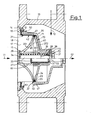
- the changeover valve has a housing 10 to which a main line, not shown, is connected, which supplies a main stream 11 from a main meter.
- a secondary flow 12 is carried by a secondary meter via a secondary line, not shown, which can be introduced into the housing 10, for example, as indicated in FIGS.
- the connection of the secondary line is variable and can also be assigned behind the housing 10 to the total flow of the measuring liquid, which is designated by 13.
- the secondary line branches off in front of the main meter, has a spring-loaded non-return valve and always carries measuring liquid.
- the housing 10 has a recess 14 for arranging a bearing body 15 which can be inserted coaxially into the housing 10.
- the bearing body 15 carries the closing member 35 to be explained below and thus forms a ready-to-install unit which can be replaced at any time and can be used in particular in existing changeover valve housings of approximately the type described in German Patent 1,960,735.
- the bearing body 15 has a bearing ring 16 which can be fastened in the recess 14 and is provided with ribs 17 running radially inwards.
- the inlet opening 18 for the main stream 11 is provided between the ribs 17.
- the bearing plate 20 has on its circumference or its parts 201 and 202 a cylindrical bearing surface 22, in which, according to FIG. 1, an annular groove 23 is formed for an oval, elastomeric sealing ring 24, which is straddled by a sliding ring 25, which a has essential U-shaped profile which is open to the inside and has radial outer surfaces on the legs.
- the slide ring 25, which has a cylindrical circumferential surface is biased radially outward within the annular groove 23.
- the sliding ring 25 bears against the inwardly facing cylindrical surface 42 of a locking ring 41 of the locking member 35.
- the bearing plate part 201 has a cylinder part 27 which is closed in the direction of the main flow 11, and the bearing plate part 202 is provided with a central cylinder part 28 which are held together by the screw connection 30 and form a cylinder space 29.
- the end of the cylinder 19 or of the cylinder part 28 pointing downstream or in the direction of the total flow 13 is closed by a base 31 with a concentric bearing bore 32.
- a piston 33 of the closing member 35 of the changeover valve is guided in the bearing bore 32 so as to be axially movable and movable.
- the piston 33 has a piston plate 34 in the region of the cylinder part 27 and has a collar 36 in the region of the cylinder part 28, which rests on the base 31 in the maximum open position of the closing member 35. In this way, the collar 36 acts as a stroke limiter.
- a helical compression spring 38 is arranged, which surrounds the piston 33 and is relatively weak is designed.
- the closing member 35 is designed as a bell-like rotating body, which can be a plastic injection molded part.
- the closing member 35 has a central rear wall section 37 which is screwed to the piston 33 and has a slightly larger diameter than the cylinder part 28. This cylindrical part 28 is overlapped by a cylindrical section 39 of the rear wall 40 of the closing member 35.
- the section 39 connects the rear wall section 37 to the actual rear wall 40.
- the closing ring 41 which is cylindrical and overlaps the bearing plate 20.
- the locking ring 41 has an inwardly facing, cylindrical surface 42 which is in engagement with the bearing surface 22 or the slide ring 25.
- a chamfer 43 is expediently formed, which springs back inwards in the direction of the surface 42.
- the otherwise radially designed end face 44 is axially adjustable relative to an annular, elastically flexible seat 45, which is formed on an elastic sealing element 46.
- the sealing element 46 is arranged on the bearing ring 16 and is designed such that when the switch valve is opened, the end face 44 of the locking ring 41 engages with the annular seat 45 longer than the annular seat 45 comes into engagement with the end face 44 when the switch valve is closed.
- the sealing element 46 can be acted upon on the side facing away from the seat 45 by the pressure of the main flow, which can be supplied directly or via a connecting channel.
- the sealing element 46 is held in the recess 14 of the housing 10 between the bearing ring 16 and a housing ring 48.
- the cylindrical locking ring 41 has in the area of the end face 44 on the outer circumference a plate-shaped extension 49 which is secured by reinforcing ribs 47 relative to the locking ring 41.
- the radial plate 49 and an intended throttle ring 10 to the housing 51 form a throttle member 50, wherein the throttle ring is formed at a slot 51, 52 formed integrally with the housing ring 4. 8
- the locking ring 41 has a plurality of axially extending channels 60. These have an always open inlet opening 61 in the region of the chamfer 43 and an outlet opening at 62, which is closed by the slide ring 25 in the locked position of the closing member 35. 3, 4 and 6, the axial channels 60 are distributed over the circumference of the locking ring 41 at equal angular distances.
- the channels 60 can extend exactly axially or be arranged in a helical shape.
- the channels 60 are open grooves in the direction of the surface 42. 4
- the cross section of the grooves 60 is dovetail-shaped, with relatively narrow slots being provided in the inwardly facing surface 42 of the locking ring 41.
- the channels 60 are designed as axial bores which are closed in the region of the inwardly facing surface 42.
- the outlet opening 62 is each formed by a radial bore.
- the outlet openings 62 are arranged in such a way that, after a slight displacement of the closing element 35 in the direction of the open position, they have a hydraulic working space 71 assigned to the closing element 35 rule actuator 70 are connected.
- the working space 71 is essentially delimited by the fixed bearing plate part 202 and the cylinder part 28 and the parts of the closing member 35 which can be moved in the manner of a piston, namely the rear wall 40, the cylindrical section 39 and the central rear wall section 37.
- the central rear wall section 37 has the presettable passage 72 for volume compensation.
- a plurality of axial through bores 73 (FIG. 7) are provided in the rear wall section 37 and can be covered by a plate-shaped element 74 which is pivotably mounted on a pin 75 on the piston 33 and can be fixed by a screw 76.
- the plate-shaped element 74 has on the side opposite the through bores 73 a pin 77 which can be used optionally in blind bores 78, as a result of which the passage 72 can be preset by the sum of the open through bores 73.
- the presetting which also serves for calibration purposes, is carried out in such a way that the sum of the cross-sectional areas of the channels 60 results in a larger flow cross-section than that of the open through bores 73.
- the bearing plate 20 is constructed somewhat differently.
- the cylinder part 27 is enclosed by a separate bearing disk 203, against which a bearing disk 204 bears, which is formed in one piece with the cylinder part 28.
- the bearing disks 203 and 204 form the bearing plate, a plurality of substantially axially extending grooves 26 being provided as channels in the outwardly facing surface 22 of the bearing disk 203.
- the grooves 26 are continuous, the outwardly facing surface 22 of the bearing plate 20 with the smooth inwardly facing surface 42 of the locking ring 41 is engaged.
- An axial valve 63 is arranged on the outlet side of the grooves 26, the valve body of which has a radial surface 64 on the rear wall 40.
- the radial surface 64 works in the locked position with an elastic, radial sealing surface 65, which is formed on an elastic sealing element 66, which has a similar structure to the sealing element 46.
- the sealing element 66 is by means of an annular disk 67 between the upstream facing the two Bearing washers 203 and 204 held. The back of the sealing element 66 is constantly under the pressure of the main flow 11 via the grooves 26.
- cylindrical pistons 79 are arranged which are guided in through bores 8 0 of the rear wall 40.
- the pistons 79 have openings 81, which form closable passages 8 2 together with the through bores 8 0 and the pistons 79, directly next to the bearing disk 204.
- the closable passages 82 together have a larger flow cross section than the sum of the channels 26 and are in the open state, ie in the blocking position of the switching valve, with the bypass flow 12, so that the working space 71 of the hydraulic actuator 70 is acted upon by the pressure of the bypass flow is.
- the end face 44 seals against the sealing element 46 and the radial sealing surface 64 against the sealing element 66.
- the pressure loss caused by the secondary counter acts on a circular cross-section which lies between the inner edge of surfaces 44/45 and the outer edge of surfaces 64/65.
- the closing member 35 is moved downstream, the through bores 80 with the cylindrical pistons 79 largely closing the passages 82, so that the pressure of the main flow 11 builds up quickly in the working space 71 after the opening of the axial valve 63 and the Rear wall 40 removed from the bearing plate 20.
- the seal contact 44/45 is initially maintained.
- the throttle member 50 Shortly before closing, when the plate-shaped extension 49 reaches the front edge of the throttle ring 51, the throttle member 50 takes effect.
- the effect of the hydraulic actuator 70 is eliminated in that the through bores 80 are pushed over the openings 81 and release them.
- the measuring liquid of the main stream 11 flowing through the grooves 26 can freely escape from the working space 71, as a result of which the increase in the effective cross section in the form of the action on the rear wall 40 is canceled immediately after opening. This results in a discharge shortly before reaching the blocking position, so that the closing member 35 is suddenly pressed into the blocking position.
- a relatively weak spring 38 can also be used here, since it only has to withstand a maximum effective pressure of 0.2 bar on the annular surface between the inner edge of the surfaces 44/45 and the outer edge of the surfaces 64/65.
- These valves 44/45 and 64/65 are designed such that when the changeover valve is opened, the axial valve 63 in front of the valve 44/45 releases the flow for the main flow 11.
- the flow rate of the volume flow when the changeover valve is opened is determined by the pressure loss of the secondary meter line including the secondary meter and the force of the spring 3 8 compared to the main flow pressure related to the size of the area of the initially applied circular ring.
- the spring-loaded backflow preventer installed in the secondary meter line is designed so that its effective pressure in the “closing” direction is equal to or greater than that exerted on the closing element when the hydraulic actuator 70 is acted upon by the pressure of the main flow 11. This precludes the secondary counter from running shortly after opening and shortly before closing, which is disadvantageous for compliance with the measurement errors in the switching range.
- a throttle member 50 If a throttle member 50 is provided, its throttle gap is designed so that the current flowing during the opening volume flow the closing member against the force of the spring 3 8 as far downstream 35 moves until the dish-shaped extension 49 downstream of the throttle ring 51 comes to lie.
- the switching valve can only be closed when the plate-shaped extension 49 is immersed in this ring 51 again, ie when the total flow has dropped to such an extent that the pressure loss occurring in the throttle element 50 and the resulting downstream force become smaller than that acting on the closing element upstream spring force.
- a change in the flow when closing is possible by additionally opening or closing the through bores 73. Due to the additional opening of such a bore, shortly before the closing, in addition to the volume flow flowing through the throttle element 50, measuring liquid can also flow through the open channels 60 and over the working space of the actuator 70 and increase the total flow before closing without increasing the pressure loss in the throttle element .
Landscapes
- Engineering & Computer Science (AREA)
- General Engineering & Computer Science (AREA)
- Physics & Mathematics (AREA)
- Fluid Mechanics (AREA)
- Mechanical Engineering (AREA)
- General Physics & Mathematics (AREA)
- Safety Valves (AREA)
- Check Valves (AREA)
- Measuring Volume Flow (AREA)
- Fluid-Driven Valves (AREA)
Priority Applications (1)
| Application Number | Priority Date | Filing Date | Title |
|---|---|---|---|
| AT82105153T ATE11330T1 (de) | 1981-06-22 | 1982-06-12 | Umschaltventil fuer verbundzaehler. |
Applications Claiming Priority (2)
| Application Number | Priority Date | Filing Date | Title |
|---|---|---|---|
| DE3124371 | 1981-06-22 | ||
| DE3124371A DE3124371C1 (de) | 1981-06-22 | 1981-06-22 | Umschaltventil fuer Verbundzaehler |
Publications (2)
| Publication Number | Publication Date |
|---|---|
| EP0068251A1 true EP0068251A1 (fr) | 1983-01-05 |
| EP0068251B1 EP0068251B1 (fr) | 1985-01-16 |
Family
ID=6135059
Family Applications (1)
| Application Number | Title | Priority Date | Filing Date |
|---|---|---|---|
| EP82105153A Expired EP0068251B1 (fr) | 1981-06-22 | 1982-06-12 | Soupape d'inversion pour compteur compound |
Country Status (5)
| Country | Link |
|---|---|
| US (1) | US4487217A (fr) |
| EP (1) | EP0068251B1 (fr) |
| JP (1) | JPS5814014A (fr) |
| AT (1) | ATE11330T1 (fr) |
| DE (1) | DE3124371C1 (fr) |
Cited By (1)
| Publication number | Priority date | Publication date | Assignee | Title |
|---|---|---|---|---|
| EP0797080A3 (fr) * | 1996-03-18 | 1998-04-01 | Ostaco AG | Vanne de réglage d'écoulement avec débitmètre |
Families Citing this family (8)
| Publication number | Priority date | Publication date | Assignee | Title |
|---|---|---|---|---|
| HU196480B (en) * | 1984-05-21 | 1988-11-28 | Jozsef Banyai | Axial-flow mechanic driven valve of internal drive |
| EP0227854B1 (fr) * | 1985-12-30 | 1990-05-09 | Johannes Erhard, H. Waldenmaier Erben Süddeutsche Armaturenfabrik GmbH & Co. | Dispositif de réduction de pression |
| DE3732703A1 (de) * | 1987-02-19 | 1988-09-01 | Spanner Pollux Gmbh | Verbundwasserzaehler |
| US4893654A (en) * | 1988-07-08 | 1990-01-16 | Feuz John G | Double check valve backflow preventer assembly |
| DE4403178C1 (de) * | 1994-02-02 | 1995-05-24 | Ziegler Horst | Volumendurchflußmesser |
| CN102424125B (zh) * | 2011-08-03 | 2014-01-15 | 合肥通用机械研究院 | 一种用于散粒料容积式组合计量法的计量装置 |
| DE102015122426B4 (de) | 2015-12-21 | 2023-05-04 | Zenner International Gmbh & Co. Kg | Verbundwasserzähler |
| RU201715U1 (ru) * | 2020-03-18 | 2020-12-29 | Общество с ограниченной ответственностью Научно-производственная фирма "МКТ-АСДМ" | Клапан обратный |
Citations (2)
| Publication number | Priority date | Publication date | Assignee | Title |
|---|---|---|---|---|
| DE323612C (de) * | 1919-07-12 | 1920-07-29 | Otto Hoffmann Dipl Ing | Umschaltventil fuer Wassermesser |
| DE1960735B1 (de) * | 1969-12-03 | 1970-12-03 | Hydrometer Gmbh | Umschaltventil für Verbundzähler |
Family Cites Families (5)
| Publication number | Priority date | Publication date | Assignee | Title |
|---|---|---|---|---|
| NL91145C (fr) * | ||||
| DE865814C (de) * | 1950-11-21 | 1953-02-05 | Hoechst Ag | Verfahren und Vorrichtung zum Zufuegen gasfoermiger oder fluessiger Medien zu stroemenden Fluessigkeiten |
| US3465778A (en) * | 1966-08-08 | 1969-09-09 | Gen Electric | Combined pressure control valve and pressure relief valve having a flat pressure-flow characteristic |
| DE3040220C1 (de) * | 1980-10-24 | 1982-03-18 | Hydrometer Gmbh, 8800 Ansbach | Umschaltventil fuer Verbundzaehler |
| US4429571A (en) * | 1982-01-25 | 1984-02-07 | Neptune Water Meter Company | Compound liquid flow meter |
-
1981
- 1981-06-22 DE DE3124371A patent/DE3124371C1/de not_active Expired
-
1982
- 1982-06-12 EP EP82105153A patent/EP0068251B1/fr not_active Expired
- 1982-06-12 AT AT82105153T patent/ATE11330T1/de not_active IP Right Cessation
- 1982-06-17 US US06/389,412 patent/US4487217A/en not_active Expired - Lifetime
- 1982-06-21 JP JP57105570A patent/JPS5814014A/ja active Granted
Patent Citations (2)
| Publication number | Priority date | Publication date | Assignee | Title |
|---|---|---|---|---|
| DE323612C (de) * | 1919-07-12 | 1920-07-29 | Otto Hoffmann Dipl Ing | Umschaltventil fuer Wassermesser |
| DE1960735B1 (de) * | 1969-12-03 | 1970-12-03 | Hydrometer Gmbh | Umschaltventil für Verbundzähler |
Cited By (1)
| Publication number | Priority date | Publication date | Assignee | Title |
|---|---|---|---|---|
| EP0797080A3 (fr) * | 1996-03-18 | 1998-04-01 | Ostaco AG | Vanne de réglage d'écoulement avec débitmètre |
Also Published As
| Publication number | Publication date |
|---|---|
| JPS5814014A (ja) | 1983-01-26 |
| DE3124371C1 (de) | 1982-11-11 |
| ATE11330T1 (de) | 1985-02-15 |
| JPH0215002B2 (fr) | 1990-04-10 |
| US4487217A (en) | 1984-12-11 |
| EP0068251B1 (fr) | 1985-01-16 |
Similar Documents
| Publication | Publication Date | Title |
|---|---|---|
| DE2832964C2 (de) | Überdruckventil, vornehmlich für hydraulische Schubkolbengetriebe von Ausbauelementen des untertägigen Grubenbetriebes | |
| DE2949231C2 (de) | Druckmittelventil, insbesondere Druckreduzierventil | |
| DE2424978A1 (de) | Rohrunterbrecher, insbesondere fuer hauswasserleitungen | |
| EP0068251B1 (fr) | Soupape d'inversion pour compteur compound | |
| EP0129569A1 (fr) | Separateur de tuyau | |
| DE69407704T2 (de) | Durchflussregelventil | |
| DE3518582A1 (de) | Rueckschlagventil fuer fluessige und luft- bzw. gasfoermige stroemungsmittel | |
| DE1932994A1 (de) | Stromregelventil | |
| DE1122788B (de) | Hahn mit am Kueken beweglich gelagertem Abschlussteil und im Gehaeuse verschiebbar gelagertem Dichtsitzring | |
| DE3034056C2 (fr) | ||
| DE1425595B2 (de) | Einrichtung zur daempfung von druckstoessen mit einem nadelventil | |
| EP0222858B2 (fr) | Sectionneur de tuyau | |
| EP1428962B1 (fr) | Ensemble piston-cylindre | |
| DE2759089A1 (de) | Schaltschieber | |
| DE2900601A1 (de) | Absperrorgan | |
| EP1001196B1 (fr) | Soupape de limitation de pression, en particulier pour des véhicules | |
| DE3840865C2 (fr) | ||
| DE1960735C2 (de) | Umschaltventil für Verbundzähler | |
| DE3518472A1 (de) | Druckbegrenzungsventil | |
| DE3040220C1 (de) | Umschaltventil fuer Verbundzaehler | |
| DE3908721C2 (fr) | ||
| DE2260799A1 (de) | Steuerventil fuer speicheranlagen, insbesondere fuer speicherbremsen von kraftfahrzeugen | |
| DE3004732C2 (fr) | ||
| DE1953955C3 (de) | Schnell öffnendes Schaltventil | |
| DE8817151U1 (de) | Hydraulisch schaltbares Wegeventil, vorzugsweise für hydraulische Ausbausysteme u.dgl. |
Legal Events
| Date | Code | Title | Description |
|---|---|---|---|
| PUAI | Public reference made under article 153(3) epc to a published international application that has entered the european phase |
Free format text: ORIGINAL CODE: 0009012 |
|
| AK | Designated contracting states |
Designated state(s): AT BE CH FR GB IT LI NL SE |
|
| 17P | Request for examination filed |
Effective date: 19830625 |
|
| ITF | It: translation for a ep patent filed | ||
| GRAA | (expected) grant |
Free format text: ORIGINAL CODE: 0009210 |
|
| AK | Designated contracting states |
Designated state(s): AT BE CH FR GB IT LI NL SE |
|
| REF | Corresponds to: |
Ref document number: 11330 Country of ref document: AT Date of ref document: 19850215 Kind code of ref document: T |
|
| ET | Fr: translation filed | ||
| PLBE | No opposition filed within time limit |
Free format text: ORIGINAL CODE: 0009261 |
|
| STAA | Information on the status of an ep patent application or granted ep patent |
Free format text: STATUS: NO OPPOSITION FILED WITHIN TIME LIMIT |
|
| 26N | No opposition filed | ||
| ITTA | It: last paid annual fee | ||
| EAL | Se: european patent in force in sweden |
Ref document number: 82105153.9 |
|
| PGFP | Annual fee paid to national office [announced via postgrant information from national office to epo] |
Ref country code: SE Payment date: 19950424 Year of fee payment: 14 |
|
| PGFP | Annual fee paid to national office [announced via postgrant information from national office to epo] |
Ref country code: CH Payment date: 19950510 Year of fee payment: 14 |
|
| PGFP | Annual fee paid to national office [announced via postgrant information from national office to epo] |
Ref country code: NL Payment date: 19950629 Year of fee payment: 14 |
|
| PG25 | Lapsed in a contracting state [announced via postgrant information from national office to epo] |
Ref country code: SE Effective date: 19960613 |
|
| PG25 | Lapsed in a contracting state [announced via postgrant information from national office to epo] |
Ref country code: LI Effective date: 19960630 Ref country code: CH Effective date: 19960630 |
|
| PG25 | Lapsed in a contracting state [announced via postgrant information from national office to epo] |
Ref country code: NL Effective date: 19970101 |
|
| REG | Reference to a national code |
Ref country code: CH Ref legal event code: PL |
|
| EUG | Se: european patent has lapsed |
Ref document number: 82105153.9 |
|
| NLV4 | Nl: lapsed or anulled due to non-payment of the annual fee |
Effective date: 19970101 |
|
| PGFP | Annual fee paid to national office [announced via postgrant information from national office to epo] |
Ref country code: FR Payment date: 19980529 Year of fee payment: 17 |
|
| PGFP | Annual fee paid to national office [announced via postgrant information from national office to epo] |
Ref country code: GB Payment date: 19980605 Year of fee payment: 17 |
|
| PGFP | Annual fee paid to national office [announced via postgrant information from national office to epo] |
Ref country code: BE Payment date: 19980610 Year of fee payment: 17 |
|
| PGFP | Annual fee paid to national office [announced via postgrant information from national office to epo] |
Ref country code: AT Payment date: 19980612 Year of fee payment: 17 |
|
| PG25 | Lapsed in a contracting state [announced via postgrant information from national office to epo] |
Ref country code: GB Free format text: LAPSE BECAUSE OF NON-PAYMENT OF DUE FEES Effective date: 19990612 Ref country code: AT Free format text: LAPSE BECAUSE OF NON-PAYMENT OF DUE FEES Effective date: 19990612 |
|
| PG25 | Lapsed in a contracting state [announced via postgrant information from national office to epo] |
Ref country code: FR Free format text: THE PATENT HAS BEEN ANNULLED BY A DECISION OF A NATIONAL AUTHORITY Effective date: 19990630 Ref country code: BE Free format text: LAPSE BECAUSE OF NON-PAYMENT OF DUE FEES Effective date: 19990630 |
|
| BERE | Be: lapsed |
Owner name: HYDROMETER G.M.B.H. Effective date: 19990630 |
|
| GBPC | Gb: european patent ceased through non-payment of renewal fee |
Effective date: 19990612 |
|
| REG | Reference to a national code |
Ref country code: FR Ref legal event code: ST |