EP0068252A2 - Dispositif d'entraînement linéaire actionné par pression de fluide - Google Patents
Dispositif d'entraînement linéaire actionné par pression de fluide Download PDFInfo
- Publication number
- EP0068252A2 EP0068252A2 EP82105158A EP82105158A EP0068252A2 EP 0068252 A2 EP0068252 A2 EP 0068252A2 EP 82105158 A EP82105158 A EP 82105158A EP 82105158 A EP82105158 A EP 82105158A EP 0068252 A2 EP0068252 A2 EP 0068252A2
- Authority
- EP
- European Patent Office
- Prior art keywords
- piston
- drive device
- slide
- pressure medium
- drive unit
- Prior art date
- Legal status (The legal status is an assumption and is not a legal conclusion. Google has not performed a legal analysis and makes no representation as to the accuracy of the status listed.)
- Ceased
Links
Images


Classifications
-
- F—MECHANICAL ENGINEERING; LIGHTING; HEATING; WEAPONS; BLASTING
- F03—MACHINES OR ENGINES FOR LIQUIDS; WIND, SPRING, OR WEIGHT MOTORS; PRODUCING MECHANICAL POWER OR A REACTIVE PROPULSIVE THRUST, NOT OTHERWISE PROVIDED FOR
- F03C—POSITIVE-DISPLACEMENT ENGINES DRIVEN BY LIQUIDS
- F03C1/00—Reciprocating-piston liquid engines
- F03C1/02—Reciprocating-piston liquid engines with multiple-cylinders, characterised by the number or arrangement of cylinders
-
- F—MECHANICAL ENGINEERING; LIGHTING; HEATING; WEAPONS; BLASTING
- F16—ENGINEERING ELEMENTS AND UNITS; GENERAL MEASURES FOR PRODUCING AND MAINTAINING EFFECTIVE FUNCTIONING OF MACHINES OR INSTALLATIONS; THERMAL INSULATION IN GENERAL
- F16H—GEARING
- F16H25/00—Gearings comprising primarily only cams, cam-followers and screw-and-nut mechanisms
- F16H25/02—Gearings comprising primarily only cams, cam-followers and screw-and-nut mechanisms the movements of two or more independently moving members being combined into a single movement
Definitions
- the present invention relates to a pressure medium-operated linear drive device for generating a relative displacement between a sled-shaped drive unit and a curve profile slide bar, the drive unit having a plurality of piston-cylinder systems which can be actuated by the pressure medium and whose pistons are supported on the profile of the slide bar and whose cylinders are each connected to the pressure medium source via control valve means.
- Linear drive devices of this type are known from DE-OS No. 2 359 779 or GB-PS No. 1 398 012.
- the structure and the mode of operation of such linear drive devices are essentially dealt with theoretically without giving any further information on possible, practical embodiments.
- the crotch elements each form self-centering sliding joint drive elements with lever means articulated on the one hand on the piston of the crotch elements and on the other hand on the slide housing.
- piston-cylinder systems are formed from air bellows springs with a piston part or from roll membranes used in the cylinders with a loose piston part, which are supported in series depending on the bottom of the slide housing, with channels the piston-cylinder - Connect the systems to the control valve means, which are also attached to the slide housing.
- Each free piston end then expediently carries a rolling element which interacts with the profile of the slide bar and is connected to one end of a pivoting lever, the other end of which is pivotably attached to the slide housing.
- the slide housing should also be supported by counter rollers on the flat side of the slide bar.
- the pressure medium can be air, water, oil and the like.
- this drive device is suitable for generating high thrust forces with the smallest construction volume, it is used according to the invention as a means for moving gates, hangar gates, sluice gates and the like
- Drive device according to the invention here is a substantial simplification of the construction concept, a large weight saving up to two-thirds of comparatively previous drives and a considerable reduction in costs.
- the drive is suitable for both industrial and private use and can be Use any slope up to vertical.
- the drive device can also be used according to the invention as a trolley, transport carriage, media distributor, etc.
- step elements 1, 2 and 3 in the form of pressure-medium-operated piston-cylinder systems to be described in more detail below are provided on a slide-shaped drive unit 10.
- step elements 1, 2 and 3 are actuated via a conventional rotary slide valve 4 by the pressure medium supplied through line 5 and are supported on a curved profile sliding strip 20.
- the rotation of the rotary valve 4 takes place during the relative movement between the drive unit 10 and the slide bar 20 via one of the thrust bar 20 parallel rack 6, on which a gear 7 of the rotary valve 4 rolls.
- the direction of movement of the movement between the drive unit 10 and the slide bar 20 is determined in a known manner by the opening angle and positions of the rotary valve, the forward and backward movement either by reversing the inlet and outlet openings for the pressure medium or by changing the relative angular position of the rotary valve the slide bar can be done. The latter can also be done by moving the rack 6.
- the rest position of the drive device is shown. Upon displacement of the rack 6 up to the stop 8 or 9 (via the shift lever 11), the step elements are advanced in one or the other direction.
- a similar analog construction can also be provided in an electrical manner by using magnets and rotary switches.
- an electrically operated or controlled embodiment there is also the possibility of replacing the rotary slide and the gear coupling by directly scanning sliding contacts, the contact tracks running parallel to the slide bar 20 and forming a linear collector.
- digital control via perforated tape or parallel control via remote display signals or the like is possible.
- FIG. 2 shows a schematic illustration of control rollers 101, 102 and 103, with which the mentioned step elements 1, 2 and 3 are supported on the profiled side 21 of the slide bar 20, with counter or support rollers 12 and 13 on the flat side for a practical embodiment 22 of the slide bar 20 roll.
- the division of the slide bar 20 and the slope of the profile 21 is variable and designed so that in each functional phase or relative position between the drive unit 10 and the slide bar 20, one of the rollers mentioned is located on a flank of the slide bar profile, so that a relative displacement between the drive unit 10 and the slide bar 20 can be triggered both in one direction and in the other.
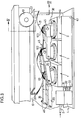
- FIGS. 3 and 4. 3 the front-side wall plate 41 (FIG. 4) for better visualization of the crotch elements 1, 2 and 3 and the associated pivot lever 35 of the pushrod drive are omitted.
- the sled-shaped drive unit with its sled housing 10 is arranged in a stationary manner on a wall 42, a frame or the like, is usually screwed on and is used here for the back and forth movement of a gate 100 or the like, on which object the curve profile Push bar 20 is fixedly arranged via an angle arm 47 (Fig.4).
- the objects to be moved are of course usually guided in displacement frames or the like.
- each piston-cylinder system 1, 2 and 3 is supported on the bottom of the slide housing 10, arranged in series, their cylinder parts being combined in a block 43.
- a so-called rolling membrane is then inserted into each of the cylinder bores, which are not visible here, and clamped with the cover part 44.
- Roll membranes and their functions are known per se and need not be described in more detail here.
- the respective piston part 30 sits on these rolling membranes with a large radial clearance and protrudes from the block 43 with its free, fork-shaped end.
- each piston-cylinder system 1, 2 and 3 is in flow communication with the rotary slide valve 4 via a line 31, 32 and 33 assigned to it, the pinion (not shown here) in the rack 6 (FIG. 4) parallel to the Push bar 20 engages in the manner described.
- each piston-cylinder system 1, 2 and 3 is suitable for absorbing and compensating for any shear force that deviates from the stroke direction, whereby for self-centering of the systems a pivot lever 35 or pairs of pivot levers or a fork-shaped pivot lever at the free end of the Piston 30 attacks and is articulated there via axes 45.
- pairs of swivel levers are provided, the other ends of which are articulated via bolts 46 on the side plates of the slide housing 10.
- a roller 101, 102 or 103 is also freely rotatable on the axis 45 in the fork-shaped end of the piston 30 in question, which rollers are supported on the cam track 21 of the slide bar 20. Then pairs of rollers 13 are used for counter-guidance, which are rotatably mounted on the slide housing 10 and which roll on the flat side 22 of the slide bar 20.
Landscapes
- Engineering & Computer Science (AREA)
- General Engineering & Computer Science (AREA)
- Mechanical Engineering (AREA)
- Chemical & Material Sciences (AREA)
- Combustion & Propulsion (AREA)
- Actuator (AREA)
- Transmission Devices (AREA)
Applications Claiming Priority (2)
| Application Number | Priority Date | Filing Date | Title |
|---|---|---|---|
| CH4025/81 | 1981-06-18 | ||
| CH4025/81A CH656925A5 (de) | 1981-06-18 | 1981-06-18 | Druckmediumbetriebene linear-antriebsvorrichtung. |
Publications (2)
| Publication Number | Publication Date |
|---|---|
| EP0068252A2 true EP0068252A2 (fr) | 1983-01-05 |
| EP0068252A3 EP0068252A3 (fr) | 1983-12-21 |
Family
ID=4268413
Family Applications (1)
| Application Number | Title | Priority Date | Filing Date |
|---|---|---|---|
| EP82105158A Ceased EP0068252A3 (fr) | 1981-06-18 | 1982-06-12 | Dispositif d'entraínement linéaire actionné par pression de fluide |
Country Status (5)
| Country | Link |
|---|---|
| US (1) | US4510845A (fr) |
| EP (1) | EP0068252A3 (fr) |
| JP (1) | JPS588860A (fr) |
| CH (1) | CH656925A5 (fr) |
| CS (1) | CS252457B2 (fr) |
Families Citing this family (4)
| Publication number | Priority date | Publication date | Assignee | Title |
|---|---|---|---|---|
| CH681636A5 (fr) * | 1989-05-30 | 1993-04-30 | Agm Ag Mueller | |
| JP2002534341A (ja) | 1999-01-14 | 2002-10-15 | スリー ワン システムズ リミテッド ライアビリティ カンパニー | 空気圧および電力供給能力を備えた荷重支持マテリアルハンドリングシステム |
| RU2210682C1 (ru) * | 2002-07-02 | 2003-08-20 | Александрова Ариадна Тимофеевна | Механизм возвратно-поступательного перемещения |
| GB0908149D0 (en) * | 2009-05-13 | 2009-06-24 | Rolls Royce Plc | Hydraulic stepper motor |
Family Cites Families (12)
| Publication number | Priority date | Publication date | Assignee | Title |
|---|---|---|---|---|
| US912183A (en) * | 1907-06-04 | 1909-02-09 | Thomas F Scollard | Steam-engine. |
| US1115470A (en) * | 1912-07-05 | 1914-10-27 | Carl E L Lipman | Air-motor. |
| GB1155001A (en) * | 1966-04-12 | 1969-06-11 | Ferranti Ltd | Improvements relating to Linear Hydraulic Motors |
| GB1209306A (en) * | 1966-12-19 | 1970-10-21 | Nat Res Dev | Improvements in or relating to linear hydraulic motors |
| US3468175A (en) * | 1967-08-15 | 1969-09-23 | Jan W Rabek | Transmission |
| US3621760A (en) * | 1969-06-02 | 1971-11-23 | Robert W Goode | Universal power unit |
| US3603211A (en) * | 1969-08-13 | 1971-09-07 | Nat Res Dev | Linear or arcuate hydraulic pump or motor |
| DE2219996C3 (de) * | 1972-04-24 | 1980-09-04 | Festo-Maschinenfabrik Gottlieb Stoll, 7300 Esslingen | Betätigungsvorrichtung mit einem elastischen, durch Druckluftbeaufschlagung ausdehnbaren, Kegelstumpfform aufweisenden faltenbalgartigen Mantel |
| GB1398012A (en) * | 1972-06-12 | 1975-06-18 | Vyzk Ustav Obrabecich Stroju | Linear hydraulic motor |
| CH559082A5 (fr) * | 1972-12-15 | 1975-02-28 | Oerlikon Buehrle Ag | |
| US3848515A (en) * | 1972-12-29 | 1974-11-19 | Ibm | Linear hydraulic drive system |
| US4211147A (en) * | 1977-06-30 | 1980-07-08 | International Business Machines Corporation | Servo-control valve for a linear hydraulic motor |
-
1981
- 1981-06-18 CH CH4025/81A patent/CH656925A5/de not_active IP Right Cessation
-
1982
- 1982-05-28 US US06/383,162 patent/US4510845A/en not_active Expired - Fee Related
- 1982-06-12 EP EP82105158A patent/EP0068252A3/fr not_active Ceased
- 1982-06-18 JP JP57104101A patent/JPS588860A/ja active Pending
- 1982-06-18 CS CS824564A patent/CS252457B2/cs unknown
Also Published As
| Publication number | Publication date |
|---|---|
| EP0068252A3 (fr) | 1983-12-21 |
| CH656925A5 (de) | 1986-07-31 |
| CS252457B2 (en) | 1987-09-17 |
| JPS588860A (ja) | 1983-01-19 |
| US4510845A (en) | 1985-04-16 |
Similar Documents
| Publication | Publication Date | Title |
|---|---|---|
| DE2440495A1 (de) | Walzgeruest | |
| DE1289369B (de) | Wellenlager mit auf Lagersegmenten gleitendem Rotor | |
| DE3331055C2 (de) | Walzgerüst mit axial verschieblichen Arbeitswalzen | |
| DE3206085C2 (fr) | ||
| DE2363143A1 (de) | Hydraulischer linearantrieb | |
| EP0068252A2 (fr) | Dispositif d'entraînement linéaire actionné par pression de fluide | |
| DE2808528A1 (de) | Bogengreifervorrichtung, bei welcher die bogengreifer in axialer richtung bewegbar sind | |
| EP0578928B1 (fr) | Dispositif d'avancement pour le transport par étapes de matériel et/ou de pièces à usiner sur ou vers des machines de production fonctionnant par intermittence | |
| DE3046989C2 (de) | Vorrichtung zum Druckan- und Druckabstellen und zum Ausführen einer für den Zylinderwechsel notwendigen Weithubbewegung eines auf den Formzylinder einer Tiefdruckrotationsmaschine wirkenden Presseurs | |
| DE1527465B2 (de) | Doppeldruck-Bolzenpresse | |
| DE2947250C2 (de) | Unmittelbar einem Extruder nachgeordnetes Walzwerk | |
| DE1908879C3 (de) | Klemmwalzenanordnung für eine vertikale Strangführung | |
| DE1611303A1 (de) | Vorrichtung zum An- und Abstellen des Druckzylinders mit der Zwischenwalze gegenueber dem Formzylinder an Tiefdruckrotationsmaschinen | |
| EP0231875A2 (fr) | Dispositif de déplacement axial des cylindres d'une cage de laminoir | |
| DE1945485B2 (de) | Vorrichtung zum Verstellen der Dichtspalte umlaufender Regenerativ-Lufrvorwärmer | |
| DE4117185A1 (de) | Schmiedepresse | |
| DE3511929A1 (de) | Elektroerosionsmaschine | |
| DE3814666C2 (fr) | ||
| EP0484623B1 (fr) | Presse à forger | |
| DE527433C (de) | Pumpe mit umlaufenden Zylindern fuer Fluessigkeitsgetriebe | |
| DE3111323A1 (de) | "gleichlaufueberwachungsvorrichtung, insbesondere fuer hebebuehnen" | |
| DE1703651B2 (fr) | ||
| DE553374C (de) | Zweizylindrische Wassersaeulenmaschine mit senkrecht auf und ab gehenden Kolben, deren Pleuelstangen ueber eine Schwinge in nachgiebiger Verbindung miteinander stehen | |
| DE691122C (de) | Exzenter-Kolbenmaschine | |
| DE1576165C (de) | Verteilervorrichtung für ein Druckmittel, das zwei doppeltwirkende hydraulische Motoren beaufschlagt |
Legal Events
| Date | Code | Title | Description |
|---|---|---|---|
| PUAI | Public reference made under article 153(3) epc to a published international application that has entered the european phase |
Free format text: ORIGINAL CODE: 0009012 |
|
| 17P | Request for examination filed |
Effective date: 19820612 |
|
| AK | Designated contracting states |
Designated state(s): AT DE FR GB IT NL SE |
|
| PUAL | Search report despatched |
Free format text: ORIGINAL CODE: 0009013 |
|
| AK | Designated contracting states |
Designated state(s): AT DE FR GB IT NL SE |
|
| STAA | Information on the status of an ep patent application or granted ep patent |
Free format text: STATUS: THE APPLICATION HAS BEEN REFUSED |
|
| 18R | Application refused |
Effective date: 19880331 |
|
| RIN1 | Information on inventor provided before grant (corrected) |
Inventor name: KAEGI, BRUNO |