EP0068280A2 - Magnetically operated electrical contact arrangement - Google Patents
Magnetically operated electrical contact arrangement Download PDFInfo
- Publication number
- EP0068280A2 EP0068280A2 EP82105222A EP82105222A EP0068280A2 EP 0068280 A2 EP0068280 A2 EP 0068280A2 EP 82105222 A EP82105222 A EP 82105222A EP 82105222 A EP82105222 A EP 82105222A EP 0068280 A2 EP0068280 A2 EP 0068280A2
- Authority
- EP
- European Patent Office
- Prior art keywords
- contact arrangement
- leg
- magnetic circuit
- contact
- permanent magnet
- Prior art date
- Legal status (The legal status is an assumption and is not a legal conclusion. Google has not performed a legal analysis and makes no representation as to the accuracy of the status listed.)
- Granted
Links
- 239000000696 magnetic material Substances 0.000 claims abstract description 4
- 239000004020 conductor Substances 0.000 claims description 6
- 230000005415 magnetization Effects 0.000 claims description 4
- 230000005489 elastic deformation Effects 0.000 claims description 2
- 230000006698 induction Effects 0.000 claims 1
- 230000000149 penetrating effect Effects 0.000 claims 1
- 229910000808 amorphous metal alloy Inorganic materials 0.000 abstract description 2
- 230000004907 flux Effects 0.000 description 4
- 239000000463 material Substances 0.000 description 3
- XEEYBQQBJWHFJM-UHFFFAOYSA-N Iron Chemical compound [Fe] XEEYBQQBJWHFJM-UHFFFAOYSA-N 0.000 description 2
- PXHVJJICTQNCMI-UHFFFAOYSA-N Nickel Chemical compound [Ni] PXHVJJICTQNCMI-UHFFFAOYSA-N 0.000 description 2
- ZOXJGFHDIHLPTG-UHFFFAOYSA-N Boron Chemical compound [B] ZOXJGFHDIHLPTG-UHFFFAOYSA-N 0.000 description 1
- 229910045601 alloy Inorganic materials 0.000 description 1
- 239000000956 alloy Substances 0.000 description 1
- 229910052796 boron Inorganic materials 0.000 description 1
- 239000010941 cobalt Substances 0.000 description 1
- 229910017052 cobalt Inorganic materials 0.000 description 1
- GUTLYIVDDKVIGB-UHFFFAOYSA-N cobalt atom Chemical compound [Co] GUTLYIVDDKVIGB-UHFFFAOYSA-N 0.000 description 1
- 238000001816 cooling Methods 0.000 description 1
- 230000000694 effects Effects 0.000 description 1
- 230000003628 erosive effect Effects 0.000 description 1
- 229910052742 iron Inorganic materials 0.000 description 1
- 239000000155 melt Substances 0.000 description 1
- 229910052752 metalloid Inorganic materials 0.000 description 1
- 150000002738 metalloids Chemical class 0.000 description 1
- 229910052759 nickel Inorganic materials 0.000 description 1
- 229910052710 silicon Inorganic materials 0.000 description 1
- 239000010703 silicon Substances 0.000 description 1
- 238000004804 winding Methods 0.000 description 1
Images

Classifications
-
- H—ELECTRICITY
- H01—ELECTRIC ELEMENTS
- H01H—ELECTRIC SWITCHES; RELAYS; SELECTORS; EMERGENCY PROTECTIVE DEVICES
- H01H36/00—Switches actuated by change of magnetic field or of electric field, e.g. by change of relative position of magnet and switch, by shielding
- H01H36/0006—Permanent magnet actuating reed switches
-
- H—ELECTRICITY
- H01—ELECTRIC ELEMENTS
- H01H—ELECTRIC SWITCHES; RELAYS; SELECTORS; EMERGENCY PROTECTIVE DEVICES
- H01H50/00—Details of electromagnetic relays
- H01H50/54—Contact arrangements
- H01H50/60—Contact arrangements moving contact being rigidly combined with movable part of magnetic circuit
-
- H—ELECTRICITY
- H01—ELECTRIC ELEMENTS
- H01H—ELECTRIC SWITCHES; RELAYS; SELECTORS; EMERGENCY PROTECTIVE DEVICES
- H01H51/00—Electromagnetic relays
- H01H51/28—Relays having both armature and contacts within a sealed casing outside which the operating coil is located, e.g. contact carried by a magnetic leaf spring or reed
- H01H51/284—Polarised relays
Definitions
- the invention relates to a magnetically actuated electrical contact arrangement with a largely closed magnetic circuit.
- the object of the invention is to provide such a contact arrangement which is constructed from a few parts and can be produced particularly simply and with small dimensions.
- This contact arrangement preferably uses a band of a largely amorphous alloy, which can be obtained from a melt by rapid cooling if, for example, in addition to the magnetic material such as iron, cobalt and / or nickel, a metalloid such as boron or silicon is present in an amount from 15 to 25 atomic% is contained in the alloy.
- a metalloid such as boron or silicon is present in an amount from 15 to 25 atomic% is contained in the alloy.
- Such Material is electrically conductive, has good soft magnetic properties and is mechanically hard and therefore elastically deformable, so that it also has good spring properties.
- the magnetic circuit consists of two U-shaped strips made of a soft magnetic material with good spring properties, the open sides of which are inserted into one another, with an electrical conductor on each strip is connectable that one leg of each band is attached to opposite sides of at least one insulating piece and that each leg of each band, at least one of which is not connected to the insulating piece, are spaced apart so that they magnetize the touch magnetic circuit with elastic deformation of at least one band and thus make a contact.
- FIG. 1 shows the contact arrangement according to the invention, which is designed here as a relay.
- two bands 1 and 2 bent into a U-shape are inserted into one another and into a coil 3.
- the leg 4 of a band 1 is fastened to the lower side of an insulating piece 6, while the leg 5 of a band 2 is firmly connected to the upper side of the insulating piece 6.
- the remaining legs 7 and 8 of the bands 1 and 2 are provided with supports 9 and 10 made of an electrically highly conductive and erosion-resistant material, as is customary, for example, with relay contacts. Between the legs 7 and 8 of the Bands 1 and 2 is a gap when the coil 3 is not energized.
- the tapes 1 and 2 are again inserted with their upper sides and provided with connection points 11 and 12 for connecting electrical conductors 13 and 14.
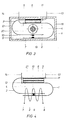
- the two inner legs 4 and 8 are attached to the two sides of an insulating piece 6; the upper leg 5 of the band 2 is fixed relative to the leg 4 of the band 1, for example by attachment to the wall of a housing 15.
- the housing 15 has between the legs 4 and 5 an incision 16 into which a disk-shaped permanent magnet 17 can be inserted. This replaces the winding of the coil 3 in Figure 1, so that the arrangement can serve as a limit switch. It is also possible to pull a tape with individual magnetized sections 16 through it and to achieve this by actuating the contact arrangement periodically.
- magnetization has the effect that an attractive force occurs between the legs 7 and 8; however, the Embodiment according to Figure 2 only move the leg 7 upwards until the contact is made.
- Figure 3 shows an embodiment in which the contact arrangement according to the invention can be used as a current sensor in an electrical cable.
- the tapes 1 and 2 are placed around in a housing 18 with an inner opening 19.
- An electrical conductor 20 or an electrical cable can be inserted through the inner opening 19, the current of which causes a magnetic field in the bands 1 and 2 and the switching of the contact arrangement in the manner described.
- FIG. 4 shows an arrangement in which the contact arrangement according to the invention acts as a direct current relay with a normally closed contact.
- the leg 4 of the tape 1 is not attached directly to the lower side of the insulating piece 6, but there is a permanent magnet 21 between the leg 4 and the insulating piece 6. This has the consequence that when the coil 3 is de-energized, the Pads 9 and 10 of the legs 7 and 8 touch each other. If a current is now allowed to flow through the coil 3, the flux in the magnetic circuit formed from the bands 1 and 2 is increased or weakened depending on the direction of the current. Since the strips 1 and 2 are mechanically prestressed in the position shown in FIG.
- the legs 7 and 8 will move apart from one another when the magnetic flux is weakened, and so the existing contact between the supports will be reached when a certain direct current is reached in the turns of the coil 3 Open 9 and 10. If the direct current in the coil 3 continues to rise, the direction of the magnetic flux in the magnetic circuit is then reversed and the contact is restored.
- This arrangement can therefore be used to indicate whether the current in the coil 3 or in a plugged-in electrical conductor according to FIG. 3 complies with a certain range or not.
Landscapes
- Physics & Mathematics (AREA)
- Electromagnetism (AREA)
- Contacts (AREA)
- Magnetic Treatment Devices (AREA)
- Electromagnets (AREA)
- Switches That Are Operated By Magnetic Or Electric Fields (AREA)
- Coupling Device And Connection With Printed Circuit (AREA)
Abstract
Zur Bildung von Relais, Endschaltern oder dergleichen werden elektrische Kontakte verwendet, die sich unter Einfluß eines Magnetfeldes öffnen bzw. schließen.Electrical contacts that open or close under the influence of a magnetic field are used to form relays, limit switches or the like.
Unter Verwendung von weichmagnetischem Material mit guten Federeigenschaften, das vorzugsweise aus einer weitgehend amorphen Legierung besteht, wird eine besonders einfach aufgebaute und empfindlich reagierende Kontaktanordnung vorgeschlagen, bei der Kontaktfeder, magentischer Kreis und magnetische Zuleitung aus lediglich zwei Bauteilen (Bänder 1 und 2) besteht.
Description
Die Erfindung betrifft eine magnetisch zu betätigende elektrische Kontaktanordnung mit einem weitgehend geschlossenen magnetischen Kreis.The invention relates to a magnetically actuated electrical contact arrangement with a largely closed magnetic circuit.
Aufgabe der Erfindung ist es, eine derartige Kontaktanordnung zu schaffen, die aus wenigen Teilen aufgebaut ist und besonders einfach und mit kleinen Abmessungen hergestellt werden kann.The object of the invention is to provide such a contact arrangement which is constructed from a few parts and can be produced particularly simply and with small dimensions.
Vorzugsweise wird bei dieser Kontaktanordnung Band aus einer weitgehend amorphen Legierung verwendet, die durch schnelles Abkühlen aus einer Schmelze erhalten werden kann, wenn beispielsweise außer dem magnetischen Material, wie Eisen, Kobalt und/oder Nickel ein Metalloid, wie z.B. Bor oder Silizium in einer Menge von 15 bis 25 Atom.-% in der Legierung enthalten ist. Derartiges Material ist elektrisch leitfähig, besitzt gute weichmagnetische Eigenschaften und ist mechanisch hart und damit elastisch verformbar, so daß es außerdem gute Federeigenschaften besitzt.This contact arrangement preferably uses a band of a largely amorphous alloy, which can be obtained from a melt by rapid cooling if, for example, in addition to the magnetic material such as iron, cobalt and / or nickel, a metalloid such as boron or silicon is present in an amount from 15 to 25 atomic% is contained in the alloy. Such Material is electrically conductive, has good soft magnetic properties and is mechanically hard and therefore elastically deformable, so that it also has good spring properties.
Unter Verwendung von derartigem Material erhält man eine besonders vorteilhafte elektrische Kontaktanordnung erfindungsgemäß dadurch, daß der magnetische Kreis aus zwei U-förmig gebogenen Bändern aus einem weichmagnetischen Material mit guten Federeigenschaften besteht, die mit ihren offenen Seiten ineinandergesteckt sind, daß an jedes Band ein elektrischer Leiter anschließbar ist, daß je ein Schenkel jedes Bandes an einander gegenüberliegenden Seiten mindestens eines Isolierstückes befestigt ist und daß weiterhin je ein Schenkel jedes Bandes, von denen mindestens einer nicht mit dem Isolierstück verbunden ist, mit Abstand nebeneinander liegen, so daß sie bei einer Magnetisierung des magnetischen Kreises unter elastischer Verformung mindestens eines Bandes sich berühren und damit einen Kontakt schließen.Using such a material, a particularly advantageous electrical contact arrangement is obtained according to the invention in that the magnetic circuit consists of two U-shaped strips made of a soft magnetic material with good spring properties, the open sides of which are inserted into one another, with an electrical conductor on each strip is connectable that one leg of each band is attached to opposite sides of at least one insulating piece and that each leg of each band, at least one of which is not connected to the insulating piece, are spaced apart so that they magnetize the touch magnetic circuit with elastic deformation of at least one band and thus make a contact.
Figur 1 zeigt die erfindungsgemäße Kontaktanordnung, die hier als Relais ausgebildet ist. Dazu sind zwei U-förmig gebogene Bänder 1 und 2 ineinander und in eine Spule 3 gesteckt. Dabei ist der Schenkel 4 eines Bandes 1 an der unteren Seite eines Isolierstückes 6 befestigt, während der Schenkel 5 eines Bandes 2 mit der oberen Seite des Isolierstückes 6 fest verbunden ist. Die übrigen Schenkel 7 und 8 der Bänder 1 und 2 sind mit Auflagen 9 und 10 aus einem elektrisch gut leitenden und abbrandfesten Material versehen, wie es beispielsweise bei Relaiskontakten üblich ist. Zwischen den Schenkeln 7 und 8 der Bänder 1 und 2 befindet sich bei nicht erregter Spule 3 ein Zwischenraum.Figure 1 shows the contact arrangement according to the invention, which is designed here as a relay. For this purpose, two
Wird nun die Spule 3 durch Anlage eines Gleich- oder Wechselstromfeldes erregt, so entsteht in den Bändern 1 und 2 ein magnetischer Fluß und die Schenkel 7 und 8 ziehen sich an bis sich die Auflagen 9 und 10 berühren und die Bänder 1 und 2 elektrisch miteinander verbinden. Die Bänder 1 und 2 sind über Anschlußpunkte 11 und 12 mit elektrischen Leitern 13 und 14 verbunden, die die Zuleitungen zu der elektrischen Kontaktanordnung darstellen.If the
In Figur 2 sind wiederum die Bänder 1 und 2 mit ihren oberen Seiten ineinandergesteckt und mit Anschlußpunkten 11 und 12 zum Anschluß elektrischer Leiter 13 und 14 versehen. Im Gegensatz zu Figur 1 sind die beiden inneren Schenkel 4 und 8 an den beiden Seiten eines Isolierstückes 6 befestigt; der obere Schenkel 5 des Bandes 2 ist - beispielsweise durch Befestigung an der Wand eines Gehäuses 15 - gegenüber dem Schenkel 4 des Bandes 1 fixiert. Das Gehäuse 15 besitzt zwischen den Schenkeln 4 und 5 einen Einschnitt 16, in den ein scheibenförmiger Dauermagnet 17 eingeschoben werden kann. Dieser ersetzt die Wicklung der Spule 3 in Figur 1, so daß die Anordnung als Endschalter dienen kann. Es ist weiterhin auch möglich, ein Band mit einzelnen aufmagnetisierten Abschnitten 16 hindurchzuziehen und dadurch zu erreichen, daß die Kontaktanordnung periodisch betätigt wird. Wie im Ausführungsbeispiel nach Figur 1 bewirkt eine Magnetisierung, daß zwischen den Schenkeln 7 und 8 eine Anziehungskraft auftritt; allerdings wird sich beim Ausführungsbeispiel nach Figur 2 lediglich der Schenkel 7 nach oben bewegen, bis der Kontakt hergestellt ist.In Figure 2, the
Figur 3 zeigt ein Ausführungsbeispiel, bei dem die erfindungsgemäße Kontaktanordnung als Stromsensor in einem elektrischen Kabel verwendet werden kann. Hierzu sind die Bänder 1 und 2 in einem Gehäuse 18 mit einer inneren Öffnung 19 herumgelegt. Durch die innere Öffnung 19 kann ein elektrischer Leiter 20 bzw. ein elektrisches Kabel gesteckt werden, dessen Strom ein Magnetfeld in den Bändern 1 und 2 und die Schaltung der Kontaktanordnung in der beschriebenen Weise bewirkt.Figure 3 shows an embodiment in which the contact arrangement according to the invention can be used as a current sensor in an electrical cable. For this purpose, the
Figur 4 zeigt eine Anordnung, bei der die erfindungsgemäße Kontaktanordnung als Gleichstromrelais mit Ruhekontakt wirkt. Im Unterschied zu Figur 1 ist der Schenkel 4 des Bandes 1 nicht unmittelbar an der unteren Seite des Isolierstückes 6 befestigt, sondern es befindet sich zwischen dem Schenkel 4 und dem Isolierstück 6 ein Dauermagnet 21. Dies hat zur Folge, daß bei stromloser Spule 3 die Auflagen 9 und 10 der Schenkel 7 und 8 einander berühren. Läßt man nun einen Strom durch die Spule 3 fließen, so wird abhängig von der Stromrichtung der Fluß in dem aus den Bändern 1 und 2 gebildeten magnetischen Kreis verstärkt oder abgeschwächt. Da die Bänder 1 und 2 in der in Figur 4 gezeigten Lage mechanisch vorgespannt sind, werden sich bei Abschwächung des magnetischen Flusses die Schenkel 7 und 8 voneinander entfernen und so bei Erreichen eines bestimmten Gleichstromes in den Windungen der Spule 3 den bestehenden Kontakt zwischen den Auflagen 9 und 10 öffnen. Bei weiter ansteigendem Gleichstrom in der Spule 3 wird dann die Richtung des Magnetflusses im magnetischen Kreis umgekehrt und der Kontakt wird wieder hergestellt. Diese Anordnung läßt sich also verwenden, um anzuzeigen, ob der Strom in der Spule 3 oder in einem durchgesteckten elektrischen Leiter entsprechend Figur 3 einen bestimmten Bereich einhält oder nicht.FIG. 4 shows an arrangement in which the contact arrangement according to the invention acts as a direct current relay with a normally closed contact. In contrast to Figure 1, the
Wenn man zwei Anordnungen, wie sie in Figur 4 dargestellt sind, nebeneinander anordnet, wobei die Magnetisierungsrichtung des Dauermagneten 21 verschieden gewählt ist, und wenn man beide Anordnungen mit einer gemeinsamen Spule versieht, so gewinnt man eine Kontaktanordnung mit zwei Kontakten, die bei niedrigem Strom beide geschlossen sind und von denen sich jeweils einer abhängig von der Stromrichtung bei ansteigendem Strom öffnet. Das Gleiche läßt sich auch dann erreichen, wenn man bei gleicher Magnetisierungsrichtung der beiden Dauermagnete 21 den Strom in unterschiedlicher Richtung durch das Innere des aus den Bändern 1 und 2 gebildeten magnetischen Kreises fließen läßt.If two arrangements, as shown in FIG. 4, are arranged side by side, the direction of magnetization of the
Claims (6)
Priority Applications (1)
| Application Number | Priority Date | Filing Date | Title |
|---|---|---|---|
| AT82105222T ATE33731T1 (en) | 1981-06-27 | 1982-06-15 | MAGNETICALLY ACTUATED ELECTRICAL CONTACT ARRANGEMENT. |
Applications Claiming Priority (2)
| Application Number | Priority Date | Filing Date | Title |
|---|---|---|---|
| DE3125346A DE3125346A1 (en) | 1981-06-27 | 1981-06-27 | MAGNETICALLY OPERATING ELECTRICAL CONTACT ARRANGEMENT |
| DE3125346 | 1981-06-27 |
Publications (3)
| Publication Number | Publication Date |
|---|---|
| EP0068280A2 true EP0068280A2 (en) | 1983-01-05 |
| EP0068280A3 EP0068280A3 (en) | 1985-05-02 |
| EP0068280B1 EP0068280B1 (en) | 1988-04-20 |
Family
ID=6135521
Family Applications (1)
| Application Number | Title | Priority Date | Filing Date |
|---|---|---|---|
| EP82105222A Expired EP0068280B1 (en) | 1981-06-27 | 1982-06-15 | Magnetically operated electrical contact arrangement |
Country Status (4)
| Country | Link |
|---|---|
| EP (1) | EP0068280B1 (en) |
| JP (1) | JPS5840722A (en) |
| AT (1) | ATE33731T1 (en) |
| DE (2) | DE3125346A1 (en) |
Families Citing this family (1)
| Publication number | Priority date | Publication date | Assignee | Title |
|---|---|---|---|---|
| US20200251296A1 (en) * | 2019-02-06 | 2020-08-06 | Honeywell International Inc. | Reed switch assembly having a customizable length of activation |
Family Cites Families (4)
| Publication number | Priority date | Publication date | Assignee | Title |
|---|---|---|---|---|
| US3278871A (en) * | 1965-01-06 | 1966-10-11 | Bell Telephone Labor Inc | Switching device having curved contacts arranged for end-on engagement |
| GB1384528A (en) * | 1971-06-19 | 1975-02-19 | Solartron Electronic Group | Scanner units |
| US3869684A (en) * | 1973-04-06 | 1975-03-04 | Int Standard Electric Corp | Bistable latching relay |
| FR2285705A2 (en) * | 1974-09-18 | 1976-04-16 | Materiel Telephonique | MINIATURE CROSSING POINT |
-
1981
- 1981-06-27 DE DE3125346A patent/DE3125346A1/en not_active Withdrawn
-
1982
- 1982-06-15 EP EP82105222A patent/EP0068280B1/en not_active Expired
- 1982-06-15 AT AT82105222T patent/ATE33731T1/en not_active IP Right Cessation
- 1982-06-15 DE DE8282105222T patent/DE3278378D1/en not_active Expired
- 1982-06-25 JP JP57109676A patent/JPS5840722A/en active Pending
Also Published As
| Publication number | Publication date |
|---|---|
| JPS5840722A (en) | 1983-03-09 |
| DE3125346A1 (en) | 1983-01-20 |
| EP0068280B1 (en) | 1988-04-20 |
| EP0068280A3 (en) | 1985-05-02 |
| DE3278378D1 (en) | 1988-05-26 |
| ATE33731T1 (en) | 1988-05-15 |
Similar Documents
| Publication | Publication Date | Title |
|---|---|---|
| DE69119073T2 (en) | SOLENOID ACTUATED SWITCHING DEVICE | |
| DE19636320C2 (en) | thermostat | |
| WO2013144218A2 (en) | Polarized electromagnetic relay and method for production thereof | |
| EP0228345A1 (en) | Magnetic-release mechanism for an earth fault circuit breaker | |
| CH630200A5 (en) | ELECTROMAGNETIC DRIVE DEVICE FOR A MINIATURE RELAY WITH AN ELECTROMAGNETIC AND MINIATURE RELAY WITH SUCH A DRIVE DEVICE. | |
| EP0727802A2 (en) | ELectromagnetic switching device, in particular contactor | |
| DE1909940A1 (en) | Electromagnetic changeover relay with protected contact system | |
| DE1563660C (en) | ||
| EP1053556B1 (en) | Electromagnetic current releasing device for electrical circuit breaker | |
| EP0068280B1 (en) | Magnetically operated electrical contact arrangement | |
| EP0327894A1 (en) | Magnetic control drive | |
| DE1563660B2 (en) | ELECTRIC SELF-SWITCH WITH A TEMPERATURE DEPENDENT MAGNETIC TRIGGER | |
| DE69415426T2 (en) | Load switch with an operating mechanism which is controlled by an electromagnetic release | |
| DE3882601T2 (en) | MAGNETOTHERMAL RELEASE UNIT FOR LOAD SWITCHES OR DIFFERENTIAL LOAD SWITCHES. | |
| DE2258922B2 (en) | Magnetically actuated, closed contact and arrangement of the same | |
| DE4445169C2 (en) | Submersible magnet system | |
| EP1644950A1 (en) | Electromagnetic switching device | |
| EP0015389B1 (en) | Miniature relay fitted in a case | |
| DE3219368A1 (en) | Electrical power circuit breaker having an electromagnetically operating trip mechanism | |
| DE2245803C3 (en) | Rotary armature relay | |
| DE1132227B (en) | Isolating and protective switches, in particular residual current circuit breakers | |
| DE2905686A1 (en) | Miniature relay for short changeover times - has shaped projection on coil forming to house spaced magnetic inserts and pole shoes | |
| DE2304775B2 (en) | Bistable, electromagnetically controllable protective tube switch | |
| DE19702818A1 (en) | Circuit for connecting or separating two part-sections of an electric cable | |
| AT225756B (en) | Electromagnetic relay, in particular for telephone systems |
Legal Events
| Date | Code | Title | Description |
|---|---|---|---|
| PUAI | Public reference made under article 153(3) epc to a published international application that has entered the european phase |
Free format text: ORIGINAL CODE: 0009012 |
|
| AK | Designated contracting states |
Designated state(s): AT CH DE FR GB IT LI NL |
|
| 17P | Request for examination filed |
Effective date: 19841208 |
|
| PUAL | Search report despatched |
Free format text: ORIGINAL CODE: 0009013 |
|
| AK | Designated contracting states |
Designated state(s): AT CH DE FR GB IT LI NL |
|
| 17Q | First examination report despatched |
Effective date: 19860120 |
|
| R17C | First examination report despatched (corrected) |
Effective date: 19860904 |
|
| ITF | It: translation for a ep patent filed | ||
| GRAA | (expected) grant |
Free format text: ORIGINAL CODE: 0009210 |
|
| AK | Designated contracting states |
Kind code of ref document: B1 Designated state(s): AT CH DE FR GB IT LI NL |
|
| REF | Corresponds to: |
Ref document number: 33731 Country of ref document: AT Date of ref document: 19880515 Kind code of ref document: T |
|
| REF | Corresponds to: |
Ref document number: 3278378 Country of ref document: DE Date of ref document: 19880526 |
|
| ET | Fr: translation filed | ||
| GBT | Gb: translation of ep patent filed (gb section 77(6)(a)/1977) | ||
| PLBE | No opposition filed within time limit |
Free format text: ORIGINAL CODE: 0009261 |
|
| STAA | Information on the status of an ep patent application or granted ep patent |
Free format text: STATUS: NO OPPOSITION FILED WITHIN TIME LIMIT |
|
| 26N | No opposition filed | ||
| PG25 | Lapsed in a contracting state [announced via postgrant information from national office to epo] |
Ref country code: GB Effective date: 19890615 Ref country code: AT Effective date: 19890615 |
|
| PG25 | Lapsed in a contracting state [announced via postgrant information from national office to epo] |
Ref country code: LI Effective date: 19890630 Ref country code: CH Effective date: 19890630 |
|
| PG25 | Lapsed in a contracting state [announced via postgrant information from national office to epo] |
Ref country code: NL Effective date: 19900101 |
|
| GBPC | Gb: european patent ceased through non-payment of renewal fee | ||
| NLV4 | Nl: lapsed or anulled due to non-payment of the annual fee | ||
| PG25 | Lapsed in a contracting state [announced via postgrant information from national office to epo] |
Ref country code: FR Free format text: LAPSE BECAUSE OF NON-PAYMENT OF DUE FEES Effective date: 19900228 |
|
| REG | Reference to a national code |
Ref country code: CH Ref legal event code: PL |
|
| PG25 | Lapsed in a contracting state [announced via postgrant information from national office to epo] |
Ref country code: DE Effective date: 19900301 |
|
| REG | Reference to a national code |
Ref country code: FR Ref legal event code: ST |