EP0068288A2 - Appareil de réproduction d'une image en couleurs - Google Patents
Appareil de réproduction d'une image en couleurs Download PDFInfo
- Publication number
- EP0068288A2 EP0068288A2 EP82105242A EP82105242A EP0068288A2 EP 0068288 A2 EP0068288 A2 EP 0068288A2 EP 82105242 A EP82105242 A EP 82105242A EP 82105242 A EP82105242 A EP 82105242A EP 0068288 A2 EP0068288 A2 EP 0068288A2
- Authority
- EP
- European Patent Office
- Prior art keywords
- horizontal
- signals
- color
- electron beams
- phosphor
- Prior art date
- Legal status (The legal status is an assumption and is not a legal conclusion. Google has not performed a legal analysis and makes no representation as to the accuracy of the status listed.)
- Granted
Links
Images


Classifications
-
- H—ELECTRICITY
- H04—ELECTRIC COMMUNICATION TECHNIQUE
- H04N—PICTORIAL COMMUNICATION, e.g. TELEVISION
- H04N9/00—Details of colour television systems
- H04N9/12—Picture reproducers
Definitions
- the present invention relates to an image display apparatus comprising a flat cathode-ray tube with a number of line cathodes.
- the present invention concerns an image display apparatus wherein its display screen is divided into a plural number of segments in the vertical direction, and to every those segments one respective electron beam is provided, and in those segments a plural number of horizontal lines are displayed by means of deflecting those respective electron beams in the vertical direction, and each segment has red, green and blue phosphor regions or subsegments disposed in horizontal direction along which horizontally divided electron beams scan in horizontal direction to display color dots to constitute the horizontal lines thereby, as a whole, a television picture image is displayed.
- a cathode-ray tube having three electron guns or a single electron gun set in a neck part of a bulky cone shaped vacuum enclosure has been used for long time.
- the shortcoming of the conventional cathode ray tube is a large depth in comparison with the size of the screen face, disabling to provide a flat and compact television set.
- EL display apparatus, plasma display apparatus or liquid crystal display apparatus has been developed, they are not sufficiently usable for practical use because they have problems in their brightness and contrast.
- the present invention is intended to provide an apparatus ; capable of displaying good detail in horizontal direction of the picture, without excessively complicating a circuit for obtaining signals which are necessary for controlling the amount of electron beams.
- This can be done by novel way of sampling the input color video signals corresponding to the respective phosphors subsegments with a time sequential relation of the colors, that is using sampling pulses of different phases for three color signals. Thereby, color resolution of the images on a display screen can be improved.
- the present invention is characterized in that, as the control signals to be impressed to control electrodes which are for controlling the light-emission intensity of respective phosphor subsegments by controlling the amount of electron beams for the R, G and B phosphor subsegments of respective horizontal segments, such sampling signals are used as to time sequentially sample the demodulated chrominance signal, for example the primary color signals (primary color signals of R, G and B), within a time period of one picture element in the horizontal direction.
- the sampling is performed simultaneously (at one time)
- the video resolution for horizontally fine parts of picture is improved as if the sampling frequency were raised very high (about three times).
- the image display.apparatus in accordance with the present invention comprises:
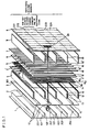
- FIG. 1 An example of the basic configuration of an image display apparatus of the present invention is shown in FIG. 1, wherein from the back part to front part the following components are provided in a flat box-shaped evacuated envelope not shown here, but preferable made of glass:
- the line cathodes 201, 202 ... form electron beam source 2, wherein horizontal line cathodes are disposed forming a vertical row, with substantially uniform gaps with each other.
- line cathodes 201, 202 ... 215 are provided, but only four of them are shown.
- the line cathodes are made by coating a tungsten wire of, for example, 10 - 20 ⁇ m diameter with known electron emitting cathode oxide. All the line cathodes are heated by feeding current thereto, and selective in-turn taking out of horizontal sheet shaped electron beam from selected one of the line cathode is done by changing a potential of the in-turn selected line cathode to negative with respect to the potential of the focussing electrode 3.
- the back electrode 1 serves to suppress emissions of electrons from other line cathodes than the selected one and also expel the electrons from the selected cathode to its front direction.
- the back'. electrode 1 may be formed by attaching conductive substance such as conductive paint on the inner wall of the back face of the flat type vacuum enclosure.
- a flat plane shaped cathode may be used in place of the row of the line electrode 201, 202 ....
- the first vertical beam-focussing electrode 3 have the slits 10 at the position to face the line cathodes 201, 202 ... and is impressed with a DC voltage, therefore horizontal sheet shaped electron beam from a selected line cathode is formed.
- the sheet shaped electron beam is then divided into a . large number (e.g. 320 in this example) of narrow electron beams by passing through the second vertical beam-focussing electrode 3', the control electrode 5 and horizontal focussing electrode 6. In FIG. 1, only one such narrow electron beam is shown for simplicity.
- Each slit 10 may have supporting ribs in midway . part of the length, or further may consists of a large number (e.g. 320) of openings with very narrow rib parts 301 inbetween.
- the electrodes 13, 13' of the vertical'deflection means 4 are disposed at levels of substantially the centers between vertically neighboring two horizontal slits 10, 10 of the vertical focussing electrode 3, and a lower electrode 13 and an upper electrode 13' are held on both faces (upper and lower faces) of an insulation board 12.
- a changing hymnage (a vertical deflection signal) is ' impressed across the pair of upper electrode and lower electrode of each pair thereby forming changing electric field for vertical deflection.
- each electron beam is deflected in a manner to have 16 levels.
- the beam control electrodes 5 comprising 320 strip electrodes 15 1 , 1 52 ... 15 320 together with the horizontal beam-focussing electrode 6 divide the horizontal sheet shaped electron beam into 320 rod shaped electron beams, and each strip electrodes 15 1 , 15 2 ... 15 320 of the beam control electrodes 5 control intensities of the rod shaped electron beams responding to the information of the video signal. Therefore, the 320 strip electrodes control information of 320 picture elements on each horizontal line.
- the 320 beam control electrodes receive 320 control signals respectively and controls the 320 rod beams in such a manner as, at one time for red color irradiation, at one time for green color irradiation and at one time for blue color irradiation, in turn.
- each picture element comprises three elementary color regions, namely red strip region, green strip region and blue strip region, which are disposed in horizontal direction.
- all the 320 beam control electrodes 15 1 , 15 2 ... 15 320 receive the beam control signals for displaying respective three primary colors, . i.e., red and blue or green, at a same tine. That is, at one moment, one horizontal line on the phosphor screen displays an image of red color parts and blue color parts of the line by impingements of red phosphor regions by odd number electron beams and impingements of blue phosphor regions by even number electron beams, at the next moment an image of green color part of the line, and at the next moment an image of red color parts and blue color part of the line by impingements of red color phosphors regions by even number electron beams and impingements of blue color phosphor regions by odd number electron beams.
- the odd number electronic switches 35 1 , 35 3 , 355 ... 35 15 switch to feed signal in the order of R, G and B
- the even number electronic switches 35 2 , 35 4 ... 35 14 switch in the order of B, G and R.
- the horizontal beam-focussing electrode 6 is a conductor sheet with a plural number, e.g. 320, of slits facing the slits 14 of the control electrodes 5 and is impressed with a DC voltage and focusses the rod shaped electron beams in horizontal direction.
- the horizontal deflection means 7 comprises strip electrodes 18, 18 ... which are disposed at the positions-in front of center positions between neighboring slits 16, 16 of the horizontal beam-focussing electrode 6.
- Each of the strip electrodes pair 18, 18' is impressed with 3-level changing voltage or a horizontal deflection signal, and horizontally deflects rod shaped electron beams, thereby deflecting electron beams of odd number and even number to opposite directions, and making the rod shaped electron beams selectively impinge red phosphor regions, green phosphor regions or blue phosphor regions in turn.
- a pair of strip electrodes are provided for each slit and whole pair are impressed with same direction voltage, both even number electron beams and odd number electron beams in the same direction.
- one horizontal deflection range corresponds to one horizontal picture element width.
- the horizontally disposed electrodes of the beam-acceleration means 8 are disposed at the height level corresponding to those of the composite body of vertical deflection electrodes 13 and 13' and are impressed with a DC voltage.
- the phosphor screen 9 may be provided with known metal back layer (not shown) formed on the side of cathodes and a positive DC voltage is impressed thereon.
- the phosphor regions are formed vertically oblong strips of red color phosphor, green color phosphor and blue color phosphor.
- horizontal broken lines on the phosphor screen 9 show boundary lines between neighboring vertically divided segments to be impinged by electron beams of respective line cathodes.
- Vertical chain lines on the phosphor screen 9 shown boundary lines between horizontally neighboring sets of three primary color phosphor strips.
- a small segment 20 which is defined by two neighboring vertical chain lines and two neighboring horizontal broken lines, is shown enlarged in schematic view of FIG. 2, wherein the small segment 20 has 16 horizontal lines in vertical row.
- one segment has the size of 16mm high in vertical direction and lmm width in horizontal direction, and in FIG. 1 the sizes are shown enlarged in widthwise direction as has been mentioned.
- 320 sets of three primary color phosphor regions are formed widthwise of the phosphor screen for 320 rod shaped electron beams produced by 320 slits 14 of the beam-control electrode 5 and 320 slits 16 of the horizontal beam-focussing.
- electrode 6 such a modification may.be made that for the 320 sets of three primary color phosphor regions, 160 rod-shaped electron beams are provided, and in this case the horizontal deflection signal is 6-level changing voltage which deflects the rod-shaped electron beam to sweep for the horizontal range of the color phosphor regions of RGBRGB, and each of the beam-control electrodes 5 also receives the control signal for two picture elements in sequence.
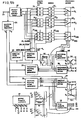
- FIG. 3 shows a circuit block diagram of a fundamental electric construction of the apparatus of FIG. 1. The explanation starts from the part to drive the cathode ray tube to form a raster on its phosphor screen.
- a power supply 22 is for impressing necessary voltages on various electrodes of the flat cathode ray tube of FIG. 1. The following DC voltages are supplied to the electrodes:
- An input terminal 23 receives ordinary composite video signal and give it to a synchronizing signal separator 24 and to a chrominance demodulator 30.
- the synchronizing signal separator 24 separate and issues vertical synchronizing signal V s and horizontal synchronizing signal H s .
- a vertical driving pulse generator 25 comprises a counter which count the horizontal synchronizing signal H s and.is reset by the vertical synchronizing signal V s , and issues 15 driving pulses pl, p2, p3 ... pl5, each having duty time of 16H (lH is the time period for one horizontal scanning).
- the fifteen pulses pl to pl5 are issued during an effective vertical sweep period, which is the time length of one vertical sweep period exclusive of vertical fly-back time and is of 240H time length.
- the driving pulses are then given to the line cathode controller 26, where they are inversed of polarity to produce pulses pl', p2', p3' ... p15'-falling down to OV at respective inversed peak period (of 16H length) and retaining 20V for other period, and is fed to respective line cathodes 201, 202, 203 ... 215.
- the line cathodes are always heated by a small voltage DC current so as to be able to emit electrons at any time, and the electrons are taken out, when the pulse of a selected line cathode is at its peak (OV), by means of positive electric field towards the vertical beam-focussing electrode 3 and subsequent other electrodes.
- the line cathodes do not emit electron beam. That is, one of the 15 line cathodes in turn emit electrons beams. Therefore,' the line cathodes are activated in turn from the top one 201 to the bottom one 215 each for 16H time period. The emitted electrons are driven forward to the vertical beam-focussing electrodes 3, 3 1 and focussed to form a horizontal sheet-shaped electron beam.
- a vertical deflection driver 27 comprises a counter for counting horizontal synchronizing signal H s and is reset by the output pulses pl, p2 ... pl5 of the vertical driving pulse generator. 25 and an A/D converter for A/D converting the count output. And the vertical deflection driver 27 issues a pair of vertical deflection signals v, v', which are 16-step rising sawtooth wave and 16-step falling sawtooth wave, respectively, both having center Voltage of V 4 . These vertical deflection signals V and v' are impressed on the upper vertical deflection electrodes 13 and the lower vertical deflection electrodes, respectively. Accordingly, the sheet shaped electron beams are vertically stepwisely deflected in 16 steps and repeat the same. And therefore, a horizontal line displayed on the phosphor screen stepwisely falls from top position to bottom position in 16 steps in one vertically divided segment 221, 222 ... or 235 of FIG. 1.
- the sheet-shaped electron beam is then divided into 320 rod-shaped electron beams having substantially round sections when passing through the vertically oblong slits 14,. 14 .... of the beam-control electrode 15 1 , 15 2 ... and vertically oblong slits 16, 16 ... of .the horizontal beam-focussing . electrode 6.
- the rod-shaped electron beams are controlled of their currents by means of voltage impressed on respective strip electrodes of the beam-control means 5, and further deflected by horizontal deflection means 7 so as to have one of three positions corresponding to R, G and B regions of the phosphor screen 9 by means of the horizontal deflection signals given by the horizontal deflection driver 29.
- a horizontal driving pulse generator 28 comprises three stages of sequentially connected monostable multivibrators, the first stages of which is triggered by horizontal synchronizing signal H. And the horizon- tal driving pulse generator issues three pulses r, g and b of the same pulse widths. For one example, an effective horizontal scanning period of 50 ⁇ sec. is divided into 3 periods for the pulses.r, g and b, accordingly, the pulses, r, g and b have 16.7p sec. pulse width each.
- the horizontal driving pulses r, g and b are given to the horizontal deflection driver 29, which is switched by the horizontal driving pulses r, g and b and issues a pair of horizontal deflection signals h and h'.
- These horizontal deflection signals h and h' are three step rising signal and three step falling signal, respectively, and, both have the same center voltage V 7 .
- These horizontal deflection signals h and h' are given to the horizontal deflection electrodes 18, 18, 18 ... and 18', 18', 18' ... dispose alternately in the horizontal deflection means 7. As a result, 320 rod-shaped electron beams are deflected at the same time to R, G or B regions on a same horizontal line of the phosphor screen.
- the number of strip electrodes 18, 18' ... of the horizontal electrodes are 320 for the 320 rod-shaped electron beams, and the strip electrodes 18, 18° ... are alternately connected to the output terminals h and h' of the horizontal deflection driver. Accordingly, the electric fields of horizontal deflection gaps defined by neighboring two strip electrodes 18 and 18' are not of the same direction. Namely, the directions of electric field of the horizontal deflection gaps are alternatingly opposite each other for neighboring horizontal deflection gaps. The effect of this alternatingly opposite electric field is compensated as will be elucidated later.
- the horizontal line on the phosphor screen at one time displays red image at the same time, at the next time green image at the same time and at the next time blue image at the same time, and at the next time the line proceed to the next lower line whereon the same is repeated.
- the beam intensity control is made as follows:
- a sampling clock generator 33 comprises PLL (phase locked loop) circuit, and issues sampling clock pulses of 6.4 MHz, which is controlled to have a predetermined phase difference against the horizontal synchronizing signal H s .
- the sampling clock pulses are given to the sampling pulse generator 34, . wherein by means of, for example, a shift register of 320 stages, 320 sampling pulses S 1 , S 2 ... S 320 , each having phase difference by 50 ⁇ sec/320 time inbetween, are produced and given to the sample hold circuits 31 1 , 31 2 ... 31 320 , respectively.
- a transferring pulse S t is issued from the sampling pulse generator 34 to the memories 32 1 , 32 2 ... 32320.
- the sampling pulses s 1 , S 2 ... S 320 correspond to 320 picture elements in the horizontal direction on the phosphor screen 9, and their timings are controlled so as to have' a constant relation with respect to the horizontal synchronizing signal H s .
- the sample-hold circuits 31 1 , 31 2 ... 31 320 sample and hold R, G and B information of video signals therein.
- the R, G and B information of the video signal for the one horizontal line stored in the memories 32 1 , 32 2 ....32 320 are led to 320 electronic switches 35 1 , 35 2 ... 35320, which are electronics switches comprising analog gate circuits for selectively leading the stored signals of a color R, G or B to the respective strip electrodes 15 1 ,..15 2 ... 15 320 of the beam control means 5.
- the switching ciricuits 35 1 , 35 2 ... 35 320 are simultaneously switched,being controlled by switching pulses given from a switching pulse generator 36, which is controlled by the output pulses r, g and b of the .. horizontal driving pulse generator 28.
- the switching circuits of the odd number orders are switched in the order of R ⁇ -G ⁇ B while the switching circuits of the even number orders are switched in the order of B ⁇ G ⁇ R, so that the effect of the alternatingly opposite directed electric fields produced by the horizontal deflection means 7 is compensated.
- timing (phases) of the switchings of the electronic switches 35 1 , 35 2 ... 35 320 and the horizontal deflection driver 29 should .be completely synchronized with each other, in order to avoide poor color impurity caused by undesirable mixing of a color signal with other color signals.
- the phosphor screen displays red color image of one horizontal line at one time, followed by green color image of the horizontal line at one time and further followed by blue color image of the horizontal line at one time, and then the same displaying is made proceeding to the next (lower) line, and thus displaying of one field having 240 horizontal lines is completed. And the displayings of the fields are repeated and television picture is obtainable on the phosphor screen 9.
- the number of the above-mentioned sample-hold circuits must be increased twice or three times, to the number of the picture elements on the line, and relevantly, the numbers of the memories should also be increased to the same number.
- each electronic switch should selectively connect the outputs of the increased number .of memories time sharingly to the corresponding beam-control electrodes.
- the primary colors of the phosphor regions are not necessarily limited to the combination of the 'R, G and B, but any other combination as the primary color of phosphors may be usable.
- the same sampling pulses are impressed at one time for all of the three primary color selections of R, G and B of a sample hold circuits (for example 31 1 or 31j or ).
- the point of time and time width are made to correspond to each picture element (for example j-th picture element) in the horizontal direction.
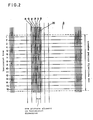
- the timing relation of those sampling pulses is shown in FIG. 4, wherein dot line pulses show the conventional sampling pulses simultaneously applied for all primary colors R, G and B.
- the pulsewidth of the sampling pulses S 1 , S 2' ... or S 320 is taken to be a time corresponding to scan for one picture element in the horizontal direction.
- each sampling pulsewidth becomes about 0.516 ⁇ sec i.e. the fundamental frequency is about 6.4 MH.
- the fundamental frequency is about 6.4 MH.
- the primary color signals has components ranging up to 3.5 to 4 MHz, and samplings of such signals necessitate sampling frequency of 7 to 8 MHz. If doing this, this causes an increase in the number of hold circuit elements (that is, memory elements) by about 20 to 30%, and brings about an undesirable cost increase.
- the present invention is to provide a new sampling method in which the sampling is performed as if the sampling frequency is increased without bringing about an increase in the number of hold circuit elements, offering a new sampling method enabling a sufficient primary color reproduction.
- those sampling pulses impressed to the sampling circuits 31 1 , 31 2 ... 31 320 for respective picture elements were impresed thereto at one time for all of R, G and B, but in the present invention, as shown in FIG. 4, pulses 1R, 1G, 1B, ... 320R, 320G, 320B where pulsewidths are about one third of those of the sampling pulses S 1 , S 2 , ...
- sampling pulses corresponding to respective primary color signals R, G and B (1R, 2R, ... 320R ; 1G, 2G, ..., 320G ; 1B, 2B, ..., 320B) have the same sampling frequencies as those of the conventional method, but their pulsewidths are about one third of those of the conventional method, and accordingly, it can be understood that the sampling frequency acts equivalently three times higher than that of the read frequency for respective R, G and B components of the video picture signals.
- FIG. 5a is an example of the part of sampling pulse generator 34' and sample holder set
- FIG. 5b is a circuit diagram of the whole circuit of the apparatus.
- input trigger pulses corresponding to the horizontal synchronization signal are impressed.
- a large number of 8-bit shift registers 52 (for example, SN74164) connected in cascade produces sampling pulses, lR, 1G, lB, 2R, 2G, 2B ... , 320R, 320G and 320B form the sampling pulse generator 34', and the sampling pulses are impressed therefrom respectively to the sample-hold circuits 31 1 , 31 2 ..., 31 320 .
- the increase. of the number of the hold-circuit elements inevitably rising up when the sampling frequency is to be increased can be prevented by means of sampling the primary color signals of R, G, and B successively by dividing one sampling period of the conventional method into three parts. Still further, concerning the video signals contained in the prinmary color signals, the sampling frequency acts as if it becomes three times higher, then the resolution in the picture images on the screen is estimated to be extending up to three times.
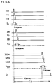
- Y represents the luminance signal and R, G, and B represent respectively the primary color signals of red, green, and blue (for example, R represents a signal that is the Y signal added by the color component of red).
- P represents a row of the R, G, and B phospor sub-segments on the screen
- X represents the control signal of the conventional method
- Z represents the control signal of the present invention. Comparing X with Z, as can be seen from a part of the signal where the color component is absent, the Z signal represents components of the original Y signal far better than X does, thereby it is understood that the present invention improves the resolution in the video picture images.
Landscapes
- Engineering & Computer Science (AREA)
- Multimedia (AREA)
- Signal Processing (AREA)
- Video Image Reproduction Devices For Color Tv Systems (AREA)
Applications Claiming Priority (2)
| Application Number | Priority Date | Filing Date | Title |
|---|---|---|---|
| JP56094994A JPS57208046A (en) | 1981-06-18 | 1981-06-18 | Image display apparatus |
| JP94994/81 | 1981-06-18 |
Publications (3)
| Publication Number | Publication Date |
|---|---|
| EP0068288A2 true EP0068288A2 (fr) | 1983-01-05 |
| EP0068288A3 EP0068288A3 (en) | 1984-09-12 |
| EP0068288B1 EP0068288B1 (fr) | 1986-11-05 |
Family
ID=14125416
Family Applications (1)
| Application Number | Title | Priority Date | Filing Date |
|---|---|---|---|
| EP82105242A Expired EP0068288B1 (fr) | 1981-06-18 | 1982-06-15 | Appareil de réproduction d'une image en couleurs |
Country Status (5)
| Country | Link |
|---|---|
| US (1) | US4408143A (fr) |
| EP (1) | EP0068288B1 (fr) |
| JP (1) | JPS57208046A (fr) |
| CA (1) | CA1199401A (fr) |
| DE (1) | DE3274175D1 (fr) |
Cited By (3)
| Publication number | Priority date | Publication date | Assignee | Title |
|---|---|---|---|---|
| EP0181052A1 (fr) * | 1984-10-01 | 1986-05-14 | Azuray, Inc. | Système à écran de visualisation de haute définition |
| WO1989008968A1 (fr) * | 1988-03-17 | 1989-09-21 | Nokia Unterhaltungselektronik (Deutschland) Gmbh | Systeme d'affichage plat en couleurs |
| WO1999054861A1 (fr) * | 1998-04-22 | 1999-10-28 | Deutsches Zentrum für Luft- und Raumfahrt e.V. | Dispositif permettant de produire une image |
Families Citing this family (6)
| Publication number | Priority date | Publication date | Assignee | Title |
|---|---|---|---|---|
| DE3235894A1 (de) * | 1982-09-28 | 1984-03-29 | Siemens AG, 1000 Berlin und 8000 München | Flache farbbild-wiedergabevorrichtung |
| US4626899A (en) * | 1983-01-14 | 1986-12-02 | Matsushita Electric Industrial Co., Ltd. | Beam scanning device producing a horizontally uniform electron beam |
| US4714863A (en) * | 1984-08-30 | 1987-12-22 | Matsushita Electric Industrial Co., Ltd. | Vibration damping means for the line cathodes of an image display apparatus |
| US5130614A (en) * | 1990-08-08 | 1992-07-14 | Massachusetts Institute Of Technology | Ribbon beam cathode ray tube |
| EP0529090B1 (fr) * | 1991-03-06 | 1996-11-27 | Miyota Kabushiki Kaisha | Dispositif cathodoluminescent |
| US6893874B2 (en) * | 2000-10-17 | 2005-05-17 | Baker Hughes Incorporated | Method for storing and transporting crude oil |
Family Cites Families (6)
| Publication number | Priority date | Publication date | Assignee | Title |
|---|---|---|---|---|
| US3720859A (en) * | 1970-05-04 | 1973-03-13 | Dicomed Corp | Image display system |
| GB1512062A (en) * | 1974-05-13 | 1978-05-24 | Sony Corp | Colour video display apparatus |
| US4158210A (en) * | 1977-09-13 | 1979-06-12 | Matsushita Electric Industrial Co., Ltd. | Picture image display device |
| US4227117A (en) * | 1978-04-28 | 1980-10-07 | Matsuhita Electric Industrial Co., Ltd. | Picture display device |
| US4216407A (en) * | 1978-11-01 | 1980-08-05 | Rca Corporation | Flat panel display device with beam collector |
| US4234825A (en) * | 1979-04-19 | 1980-11-18 | Rca Corporation | System for controlling brightness uniformity in display devices |
-
1981
- 1981-06-18 JP JP56094994A patent/JPS57208046A/ja active Granted
-
1982
- 1982-06-10 US US06/387,144 patent/US4408143A/en not_active Expired - Lifetime
- 1982-06-15 DE DE8282105242T patent/DE3274175D1/de not_active Expired
- 1982-06-15 EP EP82105242A patent/EP0068288B1/fr not_active Expired
- 1982-06-17 CA CA000405422A patent/CA1199401A/fr not_active Expired
Cited By (4)
| Publication number | Priority date | Publication date | Assignee | Title |
|---|---|---|---|---|
| EP0181052A1 (fr) * | 1984-10-01 | 1986-05-14 | Azuray, Inc. | Système à écran de visualisation de haute définition |
| WO1989008968A1 (fr) * | 1988-03-17 | 1989-09-21 | Nokia Unterhaltungselektronik (Deutschland) Gmbh | Systeme d'affichage plat en couleurs |
| WO1999054861A1 (fr) * | 1998-04-22 | 1999-10-28 | Deutsches Zentrum für Luft- und Raumfahrt e.V. | Dispositif permettant de produire une image |
| US6741225B1 (en) | 1998-04-22 | 2004-05-25 | Deutsches Zentrum Fuer Luft- Und Raumfahrt E.V. | Device for generating an image |
Also Published As
| Publication number | Publication date |
|---|---|
| EP0068288B1 (fr) | 1986-11-05 |
| JPH0332175B2 (fr) | 1991-05-10 |
| EP0068288A3 (en) | 1984-09-12 |
| JPS57208046A (en) | 1982-12-21 |
| DE3274175D1 (en) | 1986-12-11 |
| US4408143A (en) | 1983-10-04 |
| CA1199401A (fr) | 1986-01-14 |
Similar Documents
| Publication | Publication Date | Title |
|---|---|---|
| US4451846A (en) | Color image display apparatus | |
| US4449148A (en) | Image display apparatus | |
| US4451852A (en) | Image display apparatus | |
| US4523225A (en) | Image display apparatus | |
| US4408143A (en) | Color image display apparatus | |
| EP0389251B1 (fr) | Méthode pour contrôler un dispositif à présenter des images | |
| US4535272A (en) | Image display apparatus | |
| EP0094670B1 (fr) | Appareil de reproduction d'image en couleurs | |
| EP0079604B1 (fr) | Dispositif d'affichage d'images | |
| US4794449A (en) | Electron multiplier flat CRT display apparatus providing successive color scanning lines for each scanning line of a received color video signal | |
| CA1186722A (fr) | Appareil d'affichage d'images en couleurs | |
| JP2652386B2 (ja) | 画像表示装置 | |
| JPH0139626B2 (fr) | ||
| NL192159C (nl) | Kleurenbeeldweergeefinrichting. | |
| JPH0567109B2 (fr) | ||
| JPH0135463B2 (fr) | ||
| JPS5883483A (ja) | 画像表示装置 | |
| JPH0459742B2 (fr) | ||
| JPS61242490A (ja) | 画像表示装置 | |
| JPS6190578A (ja) | 画像表示装置 | |
| JPS6190592A (ja) | 画像表示装置 | |
| JPS63274991A (ja) | カラ−画像表示装置 | |
| JPH0563998B2 (fr) | ||
| JPH0746576B2 (ja) | 画像表示装置 | |
| JPS6174248A (ja) | 表示装置 |
Legal Events
| Date | Code | Title | Description |
|---|---|---|---|
| PUAI | Public reference made under article 153(3) epc to a published international application that has entered the european phase |
Free format text: ORIGINAL CODE: 0009012 |
|
| AK | Designated contracting states |
Designated state(s): DE GB NL |
|
| PUAL | Search report despatched |
Free format text: ORIGINAL CODE: 0009013 |
|
| AK | Designated contracting states |
Designated state(s): DE GB NL |
|
| 17P | Request for examination filed |
Effective date: 19841215 |
|
| GRAA | (expected) grant |
Free format text: ORIGINAL CODE: 0009210 |
|
| AK | Designated contracting states |
Kind code of ref document: B1 Designated state(s): DE GB NL |
|
| REF | Corresponds to: |
Ref document number: 3274175 Country of ref document: DE Date of ref document: 19861211 |
|
| PLBE | No opposition filed within time limit |
Free format text: ORIGINAL CODE: 0009261 |
|
| STAA | Information on the status of an ep patent application or granted ep patent |
Free format text: STATUS: NO OPPOSITION FILED WITHIN TIME LIMIT |
|
| 26N | No opposition filed | ||
| REG | Reference to a national code |
Ref country code: GB Ref legal event code: 746 Effective date: 19960628 |
|
| PGFP | Annual fee paid to national office [announced via postgrant information from national office to epo] |
Ref country code: DE Payment date: 20010611 Year of fee payment: 20 |
|
| PGFP | Annual fee paid to national office [announced via postgrant information from national office to epo] |
Ref country code: GB Payment date: 20010613 Year of fee payment: 20 |
|
| PGFP | Annual fee paid to national office [announced via postgrant information from national office to epo] |
Ref country code: NL Payment date: 20010628 Year of fee payment: 20 |
|
| REG | Reference to a national code |
Ref country code: GB Ref legal event code: IF02 |
|
| PG25 | Lapsed in a contracting state [announced via postgrant information from national office to epo] |
Ref country code: GB Free format text: LAPSE BECAUSE OF EXPIRATION OF PROTECTION Effective date: 20020614 |
|
| PG25 | Lapsed in a contracting state [announced via postgrant information from national office to epo] |
Ref country code: NL Free format text: LAPSE BECAUSE OF EXPIRATION OF PROTECTION Effective date: 20020615 |
|
| REG | Reference to a national code |
Ref country code: GB Ref legal event code: PE20 Effective date: 20020614 |
|
| NLV7 | Nl: ceased due to reaching the maximum lifetime of a patent |
Effective date: 20020615 |