EP0068312B1 - Abtaststift mit kielförmiger Spitze, und Verfahren und Vorrichtung zur Herstellung eines Abtaststiftes mit kielförmiger Spitze - Google Patents
Abtaststift mit kielförmiger Spitze, und Verfahren und Vorrichtung zur Herstellung eines Abtaststiftes mit kielförmiger Spitze Download PDFInfo
- Publication number
- EP0068312B1 EP0068312B1 EP82105283A EP82105283A EP0068312B1 EP 0068312 B1 EP0068312 B1 EP 0068312B1 EP 82105283 A EP82105283 A EP 82105283A EP 82105283 A EP82105283 A EP 82105283A EP 0068312 B1 EP0068312 B1 EP 0068312B1
- Authority
- EP
- European Patent Office
- Prior art keywords
- stylus
- groove
- pair
- keel
- shaped
- Prior art date
- Legal status (The legal status is an assumption and is not a legal conclusion. Google has not performed a legal analysis and makes no representation as to the accuracy of the status listed.)
- Expired
Links
- 238000000034 method Methods 0.000 title claims description 22
- 230000001154 acute effect Effects 0.000 claims description 7
- 241001422033 Thestylus Species 0.000 description 27
- 239000000463 material Substances 0.000 description 17
- 238000004519 manufacturing process Methods 0.000 description 16
- 238000000151 deposition Methods 0.000 description 4
- 229910003460 diamond Inorganic materials 0.000 description 4
- 239000010432 diamond Substances 0.000 description 4
- 238000012986 modification Methods 0.000 description 4
- 230000004048 modification Effects 0.000 description 4
- RTAQQCXQSZGOHL-UHFFFAOYSA-N Titanium Chemical compound [Ti] RTAQQCXQSZGOHL-UHFFFAOYSA-N 0.000 description 3
- 239000000758 substrate Substances 0.000 description 3
- 230000003319 supportive effect Effects 0.000 description 3
- 239000010936 titanium Substances 0.000 description 3
- 229910052719 titanium Inorganic materials 0.000 description 3
- 239000003082 abrasive agent Substances 0.000 description 2
- 239000007772 electrode material Substances 0.000 description 2
- 238000007373 indentation Methods 0.000 description 2
- 238000005304 joining Methods 0.000 description 2
- 229910052751 metal Inorganic materials 0.000 description 2
- 239000002184 metal Substances 0.000 description 2
- 238000001771 vacuum deposition Methods 0.000 description 2
- OKTJSMMVPCPJKN-UHFFFAOYSA-N Carbon Chemical compound [C] OKTJSMMVPCPJKN-UHFFFAOYSA-N 0.000 description 1
- BZHJMEDXRYGGRV-UHFFFAOYSA-N Vinyl chloride Chemical compound ClC=C BZHJMEDXRYGGRV-UHFFFAOYSA-N 0.000 description 1
- 229910052799 carbon Inorganic materials 0.000 description 1
- 230000008021 deposition Effects 0.000 description 1
- 238000005137 deposition process Methods 0.000 description 1
- 238000001125 extrusion Methods 0.000 description 1
- 238000003780 insertion Methods 0.000 description 1
- 230000037431 insertion Effects 0.000 description 1
- 239000002245 particle Substances 0.000 description 1
- 229920003023 plastic Polymers 0.000 description 1
- 229920003002 synthetic resin Polymers 0.000 description 1
- 239000000057 synthetic resin Substances 0.000 description 1
Images





Classifications
-
- G—PHYSICS
- G11—INFORMATION STORAGE
- G11B—INFORMATION STORAGE BASED ON RELATIVE MOVEMENT BETWEEN RECORD CARRIER AND TRANSDUCER
- G11B3/00—Recording by mechanical cutting, deforming or pressing, e.g. of grooves or pits; Reproducing by mechanical sensing; Record carriers therefor
- G11B3/44—Styli, e.g. sapphire, diamond
- G11B3/46—Constructions or forms ; Dispositions or mountings, e.g. attachment of point to shank
-
- G—PHYSICS
- G11—INFORMATION STORAGE
- G11B—INFORMATION STORAGE BASED ON RELATIVE MOVEMENT BETWEEN RECORD CARRIER AND TRANSDUCER
- G11B11/00—Recording on or reproducing from the same record carrier wherein for these two operations the methods are covered by different main groups of groups G11B3/00 - G11B7/00 or by different subgroups of group G11B9/00; Record carriers therefor
-
- B—PERFORMING OPERATIONS; TRANSPORTING
- B24—GRINDING; POLISHING
- B24B—MACHINES, DEVICES, OR PROCESSES FOR GRINDING OR POLISHING; DRESSING OR CONDITIONING OF ABRADING SURFACES; FEEDING OF GRINDING, POLISHING, OR LAPPING AGENTS
- B24B19/00—Single-purpose machines or devices for particular grinding operations not covered by any other main group
- B24B19/16—Single-purpose machines or devices for particular grinding operations not covered by any other main group for grinding sharp-pointed workpieces, e.g. needles, pens, fish hooks, tweezers or record player styli
-
- G—PHYSICS
- G11—INFORMATION STORAGE
- G11B—INFORMATION STORAGE BASED ON RELATIVE MOVEMENT BETWEEN RECORD CARRIER AND TRANSDUCER
- G11B3/00—Recording by mechanical cutting, deforming or pressing, e.g. of grooves or pits; Reproducing by mechanical sensing; Record carriers therefor
- G11B3/44—Styli, e.g. sapphire, diamond
- G11B3/445—Styli particularly adapted for sensing video discs
-
- G—PHYSICS
- G11—INFORMATION STORAGE
- G11B—INFORMATION STORAGE BASED ON RELATIVE MOVEMENT BETWEEN RECORD CARRIER AND TRANSDUCER
- G11B9/00—Recording or reproducing using a method not covered by one of the main groups G11B3/00 - G11B7/00; Record carriers therefor
- G11B9/06—Recording or reproducing using a method not covered by one of the main groups G11B3/00 - G11B7/00; Record carriers therefor using record carriers having variable electrical capacitance; Record carriers therefor
- G11B9/07—Heads for reproducing capacitive information
- G11B9/075—Heads for reproducing capacitive information using mechanical contact with record carrier, e.g. by stylus
Definitions
- the present invention relates to a stylus for playback of high density information records, such as video discs, and also to method and device for forming such a stylus.
- a video playback system of a variable capacitance form such as CED system, includes a pickup stylus, having a thin conductive electrode, and a disc record having a relatively fine spiral groove (e.g., groove width 2.6 micrometers) formed thereon.
- the groove is previously formed with geometric indentations to carry information of picture and/or sound.
- the record substrate is provided in a shape of disc made of vinyl chloride containing carbon particles.
- a keel-tipped pickup stylus has been proposed.
- Fig. 1 comprises a dielectric support element having a body 2, a terminal portion 4 and shoulders 6 and 8 joining the body 2 with the terminal portion 4.
- the keel-tipped stylus is formed by the steps of depositing the thin layer of electrode 10 on a V-shaped stylus by way of, e.g., vacuum deposition, and then, by running the V-shaped stylus 2' on an abrasive lapping disc 12 with a deep coarse-pitched groove 14, as shown in Fig. 2, with an application of a predetermined pressure in a direction indicated by an arrow A.
- the lands 16 and 18 on the lapping disc 12 lap the shoulders 6 and 8 and the walls 20 and 22 of the abrasive groove 14 form the parallel side faces of the terminal portion 4.
- a material for the electrode 10 may be undesirably deposited on side faces of the body 2, as shown in Fig. 1 by dots.
- Such a material is densely deposited in a region close to the electrode 10 and becomes sparse as the distance to the electrode 10 becomes greater.
- the undesirably deposited material on the side face of the body 2, particularly of the densely deposited region senses the information of the adjacent grooves.
- the densely deposited region is relatively long in a direction perpendicular to the electrode 10, the undesirably deposited material senses more than one piece of information at a time. The sensed information by the undesirably deposited material is introduced in the wanted signal as noise signals.
- the groove 14 of the abrasive lapping disc 12 has a very narrow groove width, such as 2 micrometers, it is necessary to present the V-shaped stylus 2' with a sharp point to properly engage the point into the groove 14.
- the point of the V-shaped stylus 2' should be so sharpened as to have a curvature less than 1 micrometer radius R, as indicated in Fig. 2.
- the pointed tip will be situated on the land 16 or 18, resulting in lapping of the pointed tip. This occurs particularly when the groove 14 of the abrasive lapping disc 12 swerves one or more micrometer in the direction indicated by an arrow B in Fig. 2, and, therefore, the possibility of landing the pointed tip on the land 16 or 18 becomes high. In this case, the pointed tip becomes undesirably flattened and, therefore, the V-shaped stylus 2' must be expelled as an unacceptable stylus, or otherwise, it must be sharpened again.
- the disc 12 may undesirably make a pitching motion in a direction perpendicular to the arrow B.
- a pitching motion may throw up and temporarily disengage the stylus 2' from the groove 14.
- the stylus 2' falls on the land 16 or 18, the pointed tip will be flattened.
- the stylus 2' falls again into the groove 14, there is such a problem that the stylus 2' may be engaged in the groove 14 in a tilted relation thereto. In this case, the lapped stylus is not acceptable.
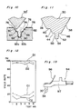
- the yield rate of styli according to the prior art showed very poor percentage as shown in graph of Fig. 12.
- abscissa and ordinate represent test number and yield rate in percentage, respectively.
- a line C1 shows percentages of styli which have been succeeded in engagement with the groove and, a line C2 shows percentage of styli which have been determined as acceptable.
- the acceptable styli is about 10 percent. Therfore, according to the prior art, it results in high manufacturing cost to obtain acceptable styli.
- the invention provides a stylus as defined in claim 1, with preferred embodiments defined in claims 2 to 8. Also, the invention provides a device for manufacturing a stylus as defined in claim 9, with preferred embodiments defined in claims 10 to 14. The invention further provides the method for manufacturing a stylus as defined in claim 15.
- any unwanted electrode material deposited on this lateral surfaces will be removed not only from the portion which enters the disc record groove but also from an adjacent area of the lateral surfaces which is outside the groove and where information from an adjacent groove might be sensed.
- the abrasive groove of the lapping disc or the like with shelves and tapering walls, not only said first and second shoulders can be formed in one operation, but also the insertion of the stylus in the abrasive groove is greatly facilitated and the risk of faulty lapping is reduced.
- a keel-tipped stylus 30 comprises a body 32 made of electrically non-conductive, hard and brittle material, such as diamond, and an electric conductive film 34, such as a metal film comprising titanium, deposited on a front face of the body 32 by any known method, for example, a vacuum deposition method.
- the body 32 is defined by: bevelled surfaces 36 and 38 intersecting at a prow line 37; and a front surface 39 extending between the bevelled surfaces 36 and 38 with a predetermined acute angle contained between the prow line 37 and the front surface 39.
- the front surface 39 is tapered, and is provided for depositing the electric conductive film 34.
- the body 32 is further defined by: first shoulders 44 and 46 extending, respectively, from opposite sides of the front surface 39 to the bevelled surfaces 36 and 38; second shoulders 40 and 42 provided adjacent to the first shoulders 44 and 46 and extending, respectively, from opposite sides of the front surface 39 to the bevelled surfaces 36 and 38; side surfaces 41 and 43 joining the first shoulders 41 and 46 to the second shoulders 40 and 42; respectively; and a terminal portion 48.
- the first and second shoulders 40, 42, 44 and 46 are parallel to each other and in perpendicular relation to an axis of the keel-tipped stylus, or they can be slightly slanted to define a downward slope towards the terminal portion 48.
- the side surfaces 41 and 43 are preferably tapered towards the terminal portion 48.
- the terminal portion 48 is defined by a pair of substantially parallel side surfaces 50 and 52 extending from the first shoulders 44 and 46, respectively, and a bottom surface 54.
- the side surfaces 50 and 52 can be slightly tapered towards the bottom surface 54.
- the bottom surface 54 is defined by a pair of slanted surfaces 54a and 54b which contain an angle of about 140 degrees to obtain a large contacting area with respect to the groove formed in the disc record.
- the slanted surfaces 54a and 54b intersects with each other along an apex line 56 which is in alignment with the prow line 37, when viewed from the bottom as shown in Fig. 6, but in bent relation with the prow line 37, when viewed from the side as shown in Fig. 5.
- the configuration of the keel-tipped stylus 30 is symmetric about its axis, as viewed in Fig. 4, and the dimension of major parts of the keel-tipped stylus 30 is as follows.
- the width W1 of the second shoulder 40 or 42 is 0.5-3.0 micrometers
- the width W2 of the first shoulder 44 or 46 is 1.5-2.0 micrometers
- the width W3 of the terminal portion 48 is 2 micrometers
- the height H1 of the side surface 41 or 43 is 2-3 micrometers
- the height H2 of the terminal portion 48 is 4 micrometers.
- the length of the apex line 56 is 4-5 micrometers. Futhermore, an angle contained by the bevelled surfaces 36 and 38 is 50-60 degrees.
- the electric conductive film 34 which has been described as deposited entirely on the front face of the body 32, can be deposited partly on the front face of the body 32 in a shape of elongated belt having the width W3 extending upwardly from the terminal portion 48.
- a device for manufacturing the keel-tipped stylus 30 comprises an abrasive lapping disc 60 mounted on a supportive turntable 62, a motor 64 connected to the turntable 62 and a holder 66 for holding a stylus to be abrased (hereinafter referred to as a V-shaped stylus 30' in contrast to the keel-tipped stylus 30).
- a clamper 68 is mounted on the abrasive lapping disc 60 to tightly hold the lapping disc 60 between the turntable 62 and the clamper 68.
- the device shown further comprises a scanner 70 for scanning the holder 66 in a radial direction over the lapping disc 60, and an electric control 72 for controlling the speed of rotation of the motor 64 and for controlling the speed of scan of the holder 60 relatively to the speed of the motor 64.
- the abrasive lapping disc 60 is formed by a flat plate having a spiral groove 74 formed therein.
- a pitch P1 between two adjacent grooves 74 and 74 is preferably about 10 to 15 micrometers.
- lands 76 are defined between the grooves 74 and 74.
- An abrasive material, such as grain of diamond is deposited on the plate to form an abrasive layer 78, as best shown in Fig. 9.
- groove 74 which has been described as formed in spiral on the plate, can be formed in concentric circles.
- the groove 74 is defined by side walls 80 and 82 extending from the lands 76 and so slanted as to widen the opening of the groove 74, shelves 84 and 86 extending from the side walls 80 and 82, respectively, a pair of side walls 88 and 90 extending downwardly from the shelves 84 and 86, respectively, and a bottom wall 92 defined by walls 92a and 92b slanted downwardly towards the center of the groove 74.
- the side walls 88 and 90 can. be parallel to each other or can be slightly tapered towards the bottom of the groove. Furthermore, the shelves 84 and 86 can be parallel to the land 76 or can be slightly slanted downwards to the center of the groove 74. Moreover, the bottom walls 92a and 92b are so slanted as to contain an angle of 140 degrees.
- the configuration of the groove 74 is symmetric about its axis, as viewed in Fig. 9, and the dimension of major parts of the groove is as follows.
- the width W4 of opening of the groove 74 i.s 8-9 micrometers
- the width W5 measured between farther edges of the shelves 84 and 86 is 4-5 micrometers
- the width W6 between the side walls 88 and 90 is 2 micrometers
- the height H3 of the slanted side wall 80 or 82 is 2-3 micrometers
- the height H4 of the side wall 88 or 90 is 4 micrometers.
- the V-shaped stylus 30' is fixedly attached to the holder 66 which is initially located above the perimeter portion of the abrasive lapping disc 60.
- the V-shaped stylus 30' is previously lapped to present a pointed end, such as a pointed end of a pyramid, and is deposited with the conductive electrode film.
- the V-shaped stylus 30' held by the holder 66 is gently lowered down until the tip of the V-shaped stylus 30' comes in contact with the running disc 60 with a determined pressure.
- the V-shaped stylus 30' should engage the groove 74 in a slight tilted manner towards forwards such that an angle contained between the electrode film 34 and the face of the abrasive lapping disc 60 is about 85 degrees.
- the tip of the V-shaped stylus 30' engages in the groove 74 with a high percentage above 90. Furthermore, since the opening of the groove 74 is relatively wide, it is possible to engage a V-shaped stylus 30' having a tip with a relatively large radius, such as 4 or 5 micrometers.
- the V-shaped stylus 30' slidingly runs along the groove 74 to lap the tip of the V-shaped stylus 30'. More particularly, the lands 76 on the lapping disc 60 lap the second shoulders 40 and 42; the side walls 80 and 82 lap the side surfaces 41 and 43; shelves 84 and 86 lap the first shoulders 44 and 46; side walls 88 and 90 lap the side surfaces 50 and 52; and the bottom walls 92a and 92b lap the slanted surfaces 54a and 54b of the bottom surface 54.
- the V-shaped stylus 30' runs over the abrasive lapping disc 60 for a required distance, a completed keel-tipped stylus 30 is obtained.
- the scanner 70 shifts the holder 66 towards the center of the disc 60 in a speed of one pitch P1 per one rotation of the disc 60. Therefore, the V-shaped stylus 30' can be applied with a pressure substantially perpendicular to the face of the disc 60.
- FIG. 10 there is shown a case in which the V-shaped stylus 30' is directed towards the groove 74 in offset relation with respect to the center of the groove 74.
- a keel-tipped stylus 30, as shown in Fig. 11 can be obtained.
- a keel-tipped stylus having a second shoulder 40 only on one side thereof is obtained.
- the yield rate of styli according to the method and device of the present invention showed an excellent percentage as shown in graph of Fig. 12.
- a line D1 shows percentages of styli which have succeeded in engagement with the groove and, a line D2 shows percentage of styli which have been determined as acceptable.
- the styli which have succeeded in engagement is nearly 100 percent and the acceptable styli is about 90 percent of all the tested pieces. Therefore, according to the present invention, a very few V-shaped styli fail to become keel-tipped styli. Thus, the manufacturing cost can be reduced.
- the holder 66 can hold a plurality of V-shaped styli 30' at the same time to form a plurality of keel-tipped styli 30 by one operation.
- the plurality of V-shaped styli 30' can be aligned in series to locate the styli 30' along the groove 74 or in parallel to locate the styli 30' in adjacent grooves 74.
- the keel-tipped stylus 30 When in use, the keel-tipped stylus 30 is mounted to a known cantilever 94 having a stylus support 95, as shown in Fig. 13.
- the electric conductive film 34 which is deposited on the body of the stylus 30, is electrically connected to a flylead 96 which serves not only as a terminal for producing signal from the electric conductive film 34, but also as a spring means to provide a predetermined pressure between the keel-tipped stylus 30 and a disc record 98 (Fig. 14).
- the disc record 98 as shown in Figs. 14 and 15 is formed by a record substrate formed by synthetic resin containing electric conductive toner.
- the disc record 98 is formed with a relatively fine spiral groove (e.g., groove width 2.6 micrometers).
- the groove is previously formed with geometric indentations to carry information of picture and/or sound.
- the keel-tipped stylus 30 engages the groove as the record is rotated by a supportive turntable (not shown), producing capacitive variations between the stylus electrode 34 and the conductive record disc. Such capacitive variations are sensed to reproduce the prerecorded information.
- the material for the electrode 34 undesirably deposited on the bevelled surfaces 36 and 38, particularly in a region close to the terminal portion 48, during the deposition process can be removed during the lapping of the shoulders 40, 42, 44 and 46. Since a distance between the adjacent groove in the record disc and the second shoulder, e.g., 40 is relatively long, the capacitance therebetween is very small and, therefore, the undesirably deposited material still remaining above the second shoulders 40 and 42 may not sense the information carried in the adjacent grooves.
- FIG. 16 there is shown another embodiment of the abrasive lapping disc 60' which further has flared walls 91 and 93 relative to the bottom wall 92 so as to further widen the opening of the groove 74.
- this embodiment is employed, the engagement between the V-shaped stylus and the groove 74 can be done with a higher percentage.
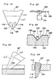
- a configuration of the V-shaped stylus 30' which is formed by an elongated body having a tapered portion 111 (A lower tip end portion 111' of the tapered portion 111 is formed by, e.g., diamond and an upper portion 111" thereof is formed by, e.g., titanium material) and a semi-cylindrical portion 112.
- the body is further defined by a plane 113 which extends over both the semi-cylindrical portion 112 and the tapered portion 111, and a pair of recesses 114 and 115 at the pointed end of the tapered portion 112.
- the plane 113 is slanted by an angle 01 (e.g., 5-18 degrees) with respect to the axis 117 of the elongated body.
- An electrode film (not shown) made of, e.g., titanium material is deposited entirely on the plane 113 by any known depositing technique.
- the recesses 114 and 115 are formed symmetrically when viewed in Fig. 17 and, as shown in Figs. 19,20 and 21, the recesses 114 and 115 are defined by a pair of shoulders 118 and 119 that extend inwardly towards the axis 117 and a pair of tapered surfaces 122 and 123.
- the tapered surfaces 122 and 123 are intersected with each other along a prow line 124 which is substantially aligned along the axis 117.
- a tip end portion 116 of the tapered end is formed with keel-tipped end, e.g., in a manner described above.
- a dotted line shown in the tip end portion 116 shows the keel-tipped end.
- Figs. 22, 23 and 24 there is shown a device for forming the recesses 114 and 115, in which Fig. 22 shows a diagrammatic view of the device, Fig. 23 shows a cross-sectional view of an abrasive lapping disc taken in a radius direction of the disc, and Fig. 24 shows a side view of a V-shaped stylus 30' having been lapped and also a cross-sectional view of an abrasive groove taken in a groove extending direction.
- the abrasive lapping disc 130 is supported on a turntable 132 which rotates at a high speed by a motor 131.
- the abrasive lapping disc 130 is formed by a substrate 133 made of plastic or metal, and a spiral groove 134 (Fig. 23) having a V-shape cross-section formed on a flat surface of the disc. It is to be noted that the groove 134 can be presented in a form of concentric circles. Furthermore, a pair of side walls 136 and 137 defining the groove 134 contain an angle 02 which is, e.g., 30-90 degrees.
- a hard and brittle abrasive material, such as grain of diamond is deposited or coated on the plate to form an abrasive layer 135.
- a material for forming the V-shaped stylus 30' is engaged in the groove 134 such that an angle 03 between the axis 117 of the material and the plane of the lapping disc 130 is adjusted to a predetermined degree, e.g., 20-70 degrees.
- the groove 134 laps the tip end of the material to define the recesses 114 and 115, thus presenting a V-shaped stylus 30'.
- the side walls 136 and 137 lap the tapered surfaces 122 and 123, and a pair of lands 138 and 139 on the opposite sides of the groove 134 lap the shoulders 118 and 119. Furthermore, a bottom corner 140 of the groove 134 forms the prow line 124. Therefore, by using the abrasive lapping disc 130 having a groove 134 and a pair of lands 138 and 139 on opposite sides of the groove 134, it is possible to automatically obtain a well sharpened V-shaped stylus 30' once the material for the stylus is adjusted in a position for the lapping.
- the pressure on the pointed tip will be lightened by the engagement between the lands 138 and 139 and the shoulders 118 and 119, respectively, and therefore, the pointed tip will not be undesirably lapped to form a rounded tip, even if the lapping disc 130 makes pitching or swerving motion.
- the abrasive lapping disc 130 can be formed by a drum having grooves formed on an outer curved face.
- FIG. 25 there is shown a condition in which the V-shaped stylus 30' is attached to a stylus holder 141. Since there is a plane 113 formed on the V-shaped stylus 30', the direction of the stylus 30', when it is held by the holder 141, can be easily determined. Furthermore, by a contact between the semi-cylindrical portion 112 and a wall 142 of the holder 141, it is possible to regulate an amount of extrusion of the stylus 30' from the holder 141. Therefore, the step for attaching the V-shaped stylus 30' to the holder 141 can be simplified.
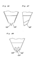
- FIG. 26 there is shown a modified V-shaped stylus.
- the V-shaped stylus shown has a pair of tapered surfaces 122' and 123' which are so curved inwardly as to present an acute prow 124'.
- Such a V-shaped stylus can be obtained by forming an abrasive groove having a corresponding curvature on its side walls.
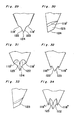
- FIG. 29 there is shown another modified V-shaped stylus.
- the V-shaped stylus shown has a pair of shoulders 118' and 119' which are flared relative to the prow 124 so that an angle contained between the shoulder, e.g. 118' and side surface 122 is an obtuse angle.
- the stylus shown can be obtained by the use of abrasive lapping disc 130' having a groove 134' as shown in Fig. 35.
- Each side of the groove 134' is defined by upper and lower walls 143a and 143b having a different slope.
- the lower wall 143b is steeper than the upper wall 143a. Therefore, it is possible to widen the opening of the groove and, thus, the engagement of the material for forming the V-shaped stylus into the groove can be carried out easily. Furthermore, by the steep walls 143b, an acute prow can be obtained.
- FIG. 32, 33 and 34 there is shown a further modified V-shaped stylus which has a pair of shoulders 118" and 119" so slanted with respect to the tapered surfaces 122 and 123 as to define an acute angle therebetween.
- the V-shaped stylus according to this modification can be obtained by the use of abrasive lapping disc 130" having a groove 134" as shown in Fig. 36. Since the disc 130"-has no land portion, the material for forming the V-shaped stylus can be engaged in the groove 134" without any failure.
- the yield rate of V-shaped styli according to the method and device described above showed very high percentage, when compared with prior art method and device, as shown in graph of Fig. 37.
- abscissa and ordinate represent test number and yield rate in percentage, respectively.
- a line E shows percentages of V-shaped styli prepared according to the above described method and device and, a line F shows percentage of V-shaped styli prepared according to the prior art method and device.
- the yield rate of the V-shaped styli prepared by the method and device described above is much higher than the yield rate according to the prior art. Therefore, by employing the above described method and device, it is possible to reduce the manufactuing cost of the V-shaped styli.
- the method for forming the V-shaped stylus described above can be carried out in two steps, the manufacturing steps can be simplified. Furthermore, according to the device for forming the V-shaped stylus described above, the stylus can be held in a proper position with respect to the stylus holder without any difficulty. Moreover, a plurality of V-shaped styli can be formed at a time and, therefore, the method and device is suitable for the mass production.
Landscapes
- Engineering & Computer Science (AREA)
- Mechanical Engineering (AREA)
- Multimedia (AREA)
- Polishing Bodies And Polishing Tools (AREA)
- Grinding And Polishing Of Tertiary Curved Surfaces And Surfaces With Complex Shapes (AREA)
- Infusion, Injection, And Reservoir Apparatuses (AREA)
- Magnetic Heads (AREA)
Claims (15)
wobei ein Paar von ersten Schultern (44, 46) in den Seitenflächen (36,38) ausgebildet ist und sich von gegenüberliegenden Seiten der Vorderfläche (39) aus erstreckt, und ein Paar von zweiten Seitenflächen (50, 52) die ersten Schultern (44,46) mit der Bodenfläche (54) des Grundkörpers verbindet und dadurch einen Abschlußteil (48) zwischen den beiden Seitenflächen (50, 52) bildet, dadurch gekennzeichnet, daß mindestens eine der Seitenflächen (36,38) mit einer zweiten Schulter (40, 42) versehen ist, die sich von einer Seitenkante der Vorderfläche (39) zu einer Stelle erstreckt, die bei und über der jeweiligen ersten Schulter (44, 46) liegt, und damit verbunden ist durch eine zweite Seitenfläche (41, 43).
Applications Claiming Priority (4)
| Application Number | Priority Date | Filing Date | Title |
|---|---|---|---|
| JP95494/81 | 1981-06-19 | ||
| JP9549481A JPS57210460A (en) | 1981-06-19 | 1981-06-19 | Scanning stylus and its manufacture |
| JP145166/81 | 1981-09-14 | ||
| JP14516681A JPS5848246A (ja) | 1981-09-14 | 1981-09-14 | スタイラス |
Publications (2)
| Publication Number | Publication Date |
|---|---|
| EP0068312A1 EP0068312A1 (de) | 1983-01-05 |
| EP0068312B1 true EP0068312B1 (de) | 1985-12-27 |
Family
ID=26436713
Family Applications (1)
| Application Number | Title | Priority Date | Filing Date |
|---|---|---|---|
| EP82105283A Expired EP0068312B1 (de) | 1981-06-19 | 1982-06-16 | Abtaststift mit kielförmiger Spitze, und Verfahren und Vorrichtung zur Herstellung eines Abtaststiftes mit kielförmiger Spitze |
Country Status (5)
| Country | Link |
|---|---|
| US (1) | US4450551A (de) |
| EP (1) | EP0068312B1 (de) |
| KR (1) | KR850001449B1 (de) |
| CA (1) | CA1174176A (de) |
| DE (1) | DE3268100D1 (de) |
Families Citing this family (15)
| Publication number | Priority date | Publication date | Assignee | Title |
|---|---|---|---|---|
| JPS58177543A (ja) * | 1982-04-09 | 1983-10-18 | Hitachi Ltd | ビデオディスク用再生針およびその製造方法 |
| KR20020011826A (ko) * | 2000-08-04 | 2002-02-09 | 김용구 | 칠보석을 이용한 수맥파 차단용 바닥재 |
| KR100417928B1 (ko) * | 2001-05-26 | 2004-02-11 | (주)지플러스 | 고로슬래그와 자극알칼리제를 첨가한 환경친화형 점토조성물 |
| US8738763B2 (en) | 2004-03-26 | 2014-05-27 | The Nielsen Company (Us), Llc | Research data gathering with a portable monitor and a stationary device |
| US7483975B2 (en) | 2004-03-26 | 2009-01-27 | Arbitron, Inc. | Systems and methods for gathering data concerning usage of media data |
| CN103000210A (zh) | 2005-10-21 | 2013-03-27 | 尼尔逊媒介研究股份有限公司 | 用于计量便携式媒体播放器的方法和装置 |
| CA2634706A1 (en) * | 2005-12-20 | 2007-06-28 | Arbitron Inc. | Methods and systems for conducting research operations |
| KR101583268B1 (ko) | 2006-03-27 | 2016-01-08 | 닐슨 미디어 리서치 인코퍼레이티드 | 무선통신장치에 표현되는 미디어 컨텐츠의 미터링 방법 및 시스템 |
| WO2008008913A2 (en) | 2006-07-12 | 2008-01-17 | Arbitron Inc. | Monitoring usage of a portable user appliance |
| WO2009088477A1 (en) | 2007-12-31 | 2009-07-16 | Arbitron, Inc. | Survey data acquisition |
| US8930003B2 (en) | 2007-12-31 | 2015-01-06 | The Nielsen Company (Us), Llc | Data capture bridge |
| US9696336B2 (en) | 2011-11-30 | 2017-07-04 | The Nielsen Company (Us), Llc | Multiple meter detection and processing using motion data |
| US9992729B2 (en) | 2012-10-22 | 2018-06-05 | The Nielsen Company (Us), Llc | Systems and methods for wirelessly modifying detection characteristics of portable devices |
| WO2014084928A1 (en) | 2012-11-30 | 2014-06-05 | Arbitron, Inc. | Multiple meter detection and processing using motion data |
| US9325381B2 (en) | 2013-03-15 | 2016-04-26 | The Nielsen Company (Us), Llc | Methods, apparatus and articles of manufacture to monitor mobile devices |
Family Cites Families (13)
| Publication number | Priority date | Publication date | Assignee | Title |
|---|---|---|---|---|
| US1817094A (en) * | 1929-01-22 | 1931-08-04 | Edison Inc Thomas A | Production of phonograph styli |
| GB655705A (en) * | 1948-09-30 | 1951-08-01 | Arpad Nagy | Improvements in or relating to the cutting and polishing of diamonds |
| DE2053866C3 (de) * | 1970-10-28 | 1974-04-04 | Ted Bildplatten Ag Aeg-Telefunkenteldec, Zug (Schweiz) | Zum Profilschleifen eines mechanischen Signalabtasters geeignetes Abspielgerät |
| DE2519172C3 (de) * | 1975-04-30 | 1980-01-31 | Ted Bildplatten Ag Aeg-Telefunken- Teldec, Zug (Schweiz) | Bildplattenspieler mit einer Poliereinrichtung für den Abtaster |
| DE2531135B2 (de) * | 1975-07-11 | 1979-07-05 | Sanyo Electric Co., Ltd., Moriguchi, Osaka (Japan) | Verfahren und Vorrichtung zum Nachschleifen des Tasters von Videoplattenspielern |
| JPS5812654B2 (ja) * | 1977-03-25 | 1983-03-09 | ア−ルシ−エ− コ−ポレ−ション | レコ−ド用畜針 |
| US4104832A (en) * | 1977-03-25 | 1978-08-08 | Rca Corporation | Method for forming keel-tipped stylus for video disc systems |
| US4098030A (en) * | 1977-03-28 | 1978-07-04 | Rca Corporation | Method for forming a narrowed-electrode pickup stylus for video disc systems |
| US4124867A (en) * | 1977-03-28 | 1978-11-07 | Rca Corporation | Narrowed-electrode pickup stylus for video disc systems |
| US4126867A (en) * | 1977-08-29 | 1978-11-21 | Silonics, Inc. | Ink jet printer driving circuit |
| US4315358A (en) * | 1980-04-21 | 1982-02-16 | Rca Corporation | Method for the manufacture of capacitive pickup styli |
| US4370739A (en) * | 1980-06-09 | 1983-01-25 | Rca Corporation | Spinel video disc playback stylus |
| JPS57152554A (en) * | 1981-03-13 | 1982-09-20 | Victor Co Of Japan Ltd | Reproducing stylus of variation detection type for electrostatic capacity value |
-
1982
- 1982-06-15 US US06/388,634 patent/US4450551A/en not_active Expired - Fee Related
- 1982-06-16 EP EP82105283A patent/EP0068312B1/de not_active Expired
- 1982-06-16 DE DE8282105283T patent/DE3268100D1/de not_active Expired
- 1982-06-16 CA CA000405271A patent/CA1174176A/en not_active Expired
- 1982-06-17 KR KR8202695A patent/KR850001449B1/ko not_active Expired
Also Published As
| Publication number | Publication date |
|---|---|
| DE3268100D1 (en) | 1986-02-06 |
| US4450551A (en) | 1984-05-22 |
| KR840000856A (ko) | 1984-02-27 |
| CA1174176A (en) | 1984-09-11 |
| EP0068312A1 (de) | 1983-01-05 |
| KR850001449B1 (ko) | 1985-10-05 |
Similar Documents
| Publication | Publication Date | Title |
|---|---|---|
| US4450551A (en) | Keel-tipped stylus, and method and device for making keel-tipped stylus | |
| US4104832A (en) | Method for forming keel-tipped stylus for video disc systems | |
| US4162510A (en) | Keel-tipped stylus for video disc systems | |
| US4165560A (en) | Method for manufacturing a diamond stylus for video disc players | |
| US3826877A (en) | Information playback system stylus | |
| CA1075810A (en) | Video disc stylus | |
| US5155306A (en) | Switch substrate and method of manufacture | |
| US4152641A (en) | Method and apparatus for the determination of signal pickup qualities of a stylus of a capacitive disc video player | |
| US4199782A (en) | Stylus for reproducing capacitive videodisc | |
| US4439855A (en) | Capacitive playback stylus | |
| US4098030A (en) | Method for forming a narrowed-electrode pickup stylus for video disc systems | |
| US4124867A (en) | Narrowed-electrode pickup stylus for video disc systems | |
| JPS5812654B2 (ja) | レコ−ド用畜針 | |
| US4273967A (en) | Stylus for reproducing capacitive videodisc | |
| US3774918A (en) | Phonograph pickup stylus | |
| US4497052A (en) | Stylus for reproducing information signals recorded on a recording medium | |
| US4375095A (en) | Method and apparatus for testing styli | |
| GB1601448A (en) | Narrowed-electrode pcikup stylus and forming methods for video disc systems | |
| US4534136A (en) | Information signal regenerating stylus and manufacturing method thereof | |
| US4371961A (en) | Capacitive information system | |
| US4439853A (en) | Capacitive playback stylus | |
| US4488281A (en) | Capacitance detection type record stylus having a conductive shank | |
| US4439854A (en) | Video disc stylus | |
| NL8000898A (nl) | Weergeefstift voor informatiesignaalregistreermedium van elektrostatisch capacitieve soort. | |
| EP0087020B1 (de) | Abtaststift und Verfahren zu seiner Herstellung |
Legal Events
| Date | Code | Title | Description |
|---|---|---|---|
| PUAI | Public reference made under article 153(3) epc to a published international application that has entered the european phase |
Free format text: ORIGINAL CODE: 0009012 |
|
| AK | Designated contracting states |
Designated state(s): DE FR GB |
|
| 17P | Request for examination filed |
Effective date: 19830616 |
|
| GRAA | (expected) grant |
Free format text: ORIGINAL CODE: 0009210 |
|
| AK | Designated contracting states |
Designated state(s): DE FR GB |
|
| REF | Corresponds to: |
Ref document number: 3268100 Country of ref document: DE Date of ref document: 19860206 |
|
| ET | Fr: translation filed | ||
| PLBE | No opposition filed within time limit |
Free format text: ORIGINAL CODE: 0009261 |
|
| STAA | Information on the status of an ep patent application or granted ep patent |
Free format text: STATUS: NO OPPOSITION FILED WITHIN TIME LIMIT |
|
| 26N | No opposition filed | ||
| PGFP | Annual fee paid to national office [announced via postgrant information from national office to epo] |
Ref country code: GB Payment date: 19910610 Year of fee payment: 10 |
|
| PGFP | Annual fee paid to national office [announced via postgrant information from national office to epo] |
Ref country code: FR Payment date: 19910619 Year of fee payment: 10 |
|
| PGFP | Annual fee paid to national office [announced via postgrant information from national office to epo] |
Ref country code: DE Payment date: 19910723 Year of fee payment: 10 |
|
| PG25 | Lapsed in a contracting state [announced via postgrant information from national office to epo] |
Ref country code: GB Effective date: 19920616 |
|
| GBPC | Gb: european patent ceased through non-payment of renewal fee |
Effective date: 19920616 |
|
| PG25 | Lapsed in a contracting state [announced via postgrant information from national office to epo] |
Ref country code: FR Effective date: 19930226 |
|
| PG25 | Lapsed in a contracting state [announced via postgrant information from national office to epo] |
Ref country code: DE Effective date: 19930302 |
|
| REG | Reference to a national code |
Ref country code: FR Ref legal event code: ST |