EP0068381B1 - Charrue tractée par tracteur - Google Patents
Charrue tractée par tracteur Download PDFInfo
- Publication number
- EP0068381B1 EP0068381B1 EP82105420A EP82105420A EP0068381B1 EP 0068381 B1 EP0068381 B1 EP 0068381B1 EP 82105420 A EP82105420 A EP 82105420A EP 82105420 A EP82105420 A EP 82105420A EP 0068381 B1 EP0068381 B1 EP 0068381B1
- Authority
- EP
- European Patent Office
- Prior art keywords
- main frame
- furrow
- furrow wheel
- plough
- motor
- Prior art date
- Legal status (The legal status is an assumption and is not a legal conclusion. Google has not performed a legal analysis and makes no representation as to the accuracy of the status listed.)
- Expired
Links
Images


Classifications
-
- A—HUMAN NECESSITIES
- A01—AGRICULTURE; FORESTRY; ANIMAL HUSBANDRY; HUNTING; TRAPPING; FISHING
- A01B—SOIL WORKING IN AGRICULTURE OR FORESTRY; PARTS, DETAILS, OR ACCESSORIES OF AGRICULTURAL MACHINES OR IMPLEMENTS, IN GENERAL
- A01B63/00—Lifting or adjusting devices or arrangements for agricultural machines or implements
- A01B63/14—Lifting or adjusting devices or arrangements for agricultural machines or implements for implements drawn by animals or tractors
- A01B63/16—Lifting or adjusting devices or arrangements for agricultural machines or implements for implements drawn by animals or tractors with wheels adjustable relatively to the frame
- A01B63/22—Lifting or adjusting devices or arrangements for agricultural machines or implements for implements drawn by animals or tractors with wheels adjustable relatively to the frame operated by hydraulic or pneumatic means
-
- A—HUMAN NECESSITIES
- A01—AGRICULTURE; FORESTRY; ANIMAL HUSBANDRY; HUNTING; TRAPPING; FISHING
- A01B—SOIL WORKING IN AGRICULTURE OR FORESTRY; PARTS, DETAILS, OR ACCESSORIES OF AGRICULTURAL MACHINES OR IMPLEMENTS, IN GENERAL
- A01B3/00—Ploughs with fixed plough-shares
- A01B3/24—Tractor-drawn ploughs
- A01B3/26—Tractor-drawn ploughs without alternating possibility
Definitions
- the invention relates to a plow drawn by a tractor with the features of the preamble of claim 1.
- Such a plow is known from US Pat. No. 3,731,749.
- the main frame is supported on three wheels so that the height of the main frame is not controlled by an adjustable pulling device.
- the known plow requires three thrust piston motors and an additional hand-adjustable adjustment device for adjusting the front furrow wheel between the plow position and the normal working position.
- this comprises an idle travel and adjustment device. This has an idle arm which can be freely pivoted on the main frame between two stops and to which a two-armed adjusting lever is articulated.
- the main frame can be lowered further compared to the front furrow wheel that is seated on the surface of the field when plowing.
- This further lowering movement is limited by a separate adjustable stop device. Thanks to the free travel arm, the push-piston engine can continue the retracting movement of its piston rod even if the main frame is prevented from following by the stop device.
- the adjustable or adjustable link is mounted directly on the main frame.
- An empty travel device in the connection between the thrust piston motor and the main frame is not necessary.
- the adjustable link on the main frame is automatically adjusted, depending on the retracting movement of the associated thrust piston motor and regardless of the desired setting of the furrow impeller.
- the arrangement according to the invention is thus much simpler, since it requires far fewer parts, requires significantly fewer adjustment steps and is therefore extremely easy to use in its changeover.
- Both stable positions which correspond to plowing or normal plowing, are determined solely by the mechanical design of the few parts of the adjustment device. Locking the convertible link is not absolutely necessary to maintain each of the two stable positions per se, but merely represents an additional safety measure. Locking is much easier, since the stable positions are automatically predetermined by the shape of the parts and the device is not under pretensioning forces and can therefore be easily operated by the driver.
- FIG. 1 shows a tandem flight with a front main frame and a main frame 22 lying opposite it, which are connected to one another in an articulated manner about an essentially transverse axis and are inclined in their position obliquely to the direction of travel.
- the front main frame 20 has a number of typical plow bodies 26, some of which are omitted for ease of illustration. The same applies to the plow bodies 28 of the rear main frame 22.
- the front main frame 20 is rigidly connected to a pull rod 30 which extends forward, the rigid connection being intended to be present at least with respect to relative vertical movements.
- the pull rod is supported at its front end by a train connection device 32 which comprises a rigid connecting member 34 which is connected to the connecting member 38 of the agricultural tractor 36 and is supported by the latter.
- Patent protection for the train connection device 32 is claimed in European Patent Application No. 84115705.0 (EP-A-0145027).
- the front right end 40 lies on the right and in front of the left front end, which is represented by the drawbar.
- the front right end of the main frame 20 is supported by a furrow wheel 42 through a support linkage 44.
- the rear end of the main frame 20 as well as the front end of the rear main frame 22 are supported on the ground by a wheeled bogie 46 while the rear end of the rear frame is typically supported by a further furrow wheel 48 and a feeler wheel 50.
- FIG. 1 The right front end of the main frame 20 on the furrow wheel 42 is supported by means of the support rod 44.
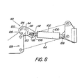
- Figures 2 to 8 best show details of the linkage, the lifting device and the other parts.
- the furrow impeller includes an axis, not shown, which is rigidly connected to an upright shaft 92, which is pivotable about a vertical axis in a bearing housing 94.
- the front end of the main frame 20 rigidly carries a holder 96.
- the support linkage 44 has two parallel links 98 which are articulated at their opposite ends to the bearing housing 94 or the holder 96 of the main frame.
- a double-acting hydraulic motor in the form of a reciprocating piston engine 100 lies between the bearing housing and the holder 96 and parallel to the support linkage, so that a relative lifting movement and lowering movement can be carried out between the main frame and the furrow impeller.
- this lifting and lowering movement of the main frame is coordinated via the furrow impeller with the corresponding lifting and lowering movement by the train connection 32.
- the hydraulic motor 100 comprises a cylinder 102, a piston and a piston rod 106.
- the closed end of the cylinder has an articulated connection 108 with a carrier 94 for the furrow impeller.
- the piston rod extends upwards and backwards to a connecting device 110 with the holder 96.
- bistable link As a bistable link, this has an arm 112 which can be pivoted on the holder 96 about a cross pin 114. To simplify and clarify, it is assumed that the arm moves from front to back and vice versa. However, these terms are only to be understood here relatively and not in a limited sense.
- the arm extends essentially downwards. Its free end is connected to the end of the piston rod 106 via a cross pin 116 so that the extension and retraction of the motor pivots the arm.
- the pivoting of the arm is limited in angular extent between two positions on opposite sides of a straight line drawn between the cylinder anchor pin 108 and the pivot axis 114 of the arm. Controlled movement of the arm in these two phases is achieved by front and rear stops 118 and 120. These are provided on the arm and can cooperate with corresponding front and rear sections or projections 122 and 124 of the holder 96 according to FIG. 6.
- Figures 3 and 6 show the components in the fully raised transport position of the plow. The furrow impeller motor is extended.
- the arm is pivoted forward into a position in contact with the rear stop. This prevents further counterclockwise pivoting.
- a pin 126 can be inserted into the arm and holder through aligned openings (not numbered) to lock the arm in this position. When the pin 126 is not needed, it can be inserted into the opening 128 in a non-use position.
- the pin 126 is left in place and the motor 100 is retracted. However, if there is no furrow, as is the case when plowing a field, pin 126 is removed and the motor is retracted. Since the plow has to be lowered by a larger amount than the furrow wheel when the furrow wheel is not in one Furrow is located, the arm can turn over its middle position until the stop elements 118 and 122 come to rest against each other (Fig. 7). This is because the furrow wheel runs on the top of the field and is therefore in a higher position than when running in a furrow.
- the plow is lowered to the ground until the associated hydraulic motor allows the arm to pivot past the center position to abut the stop members 120, 124 .
- the pin 126 is then inserted into the locking position in the upper openings of the arm and holder.
- the mode of operation of the bistable device can perhaps be better understood when describing the lowering of the plow from the position according to FIG. 6 to the position according to FIG. 7.
- the pin 126 is removed from the locked position and inserted into the opening 128.
- the furrow impeller swings essentially around pin 116 until the line through points 108, 116, 114 is reached. This is the dead center line.
- arm 112 snaps past the dead center line in a clockwise direction. A return to the raised position from the work-on position is possible with the arm in the same position.
- the hydraulic motor 100 is extended.
- the raised position of the plow is at a constant height, regardless of whether it is raised from the plowed position or from the normal working position.
- the bistable device ensures two different relative positions of the furrow wheel.
- the plow In order to change from the plowing position to the normal working position, the plow is brought into a position in which the furrow wheel can enter a furrow. The plow is still lying on the unploughed field, while the furrow wheel is literally hanging in the air. At that moment, the tractor is stopped and the hydraulic motor in question is retracted so that the plow penetrates the ground. If the engine is retracted further, the wheel is raised from the furrow floor. As a result, the arm 112 is pivoted counterclockwise until the stops 120, 124 take effect (FIG. 8). The pin 126 is inserted into its locked position (upper hole) to maintain this position for normal operation. When the tractor is moved forward, the plow bodies step into the ground and the furrow wheel runs in furrow.
- the operation of the motors for the train connection and for the furrow impeller is essentially synchronous, with the result that the front ends of the plow maintain their spatial position during lifting and lowering.
- the control device for the furrow impeller in particular in connection with the bistable arm 112, provides the necessary compensation for different functions when lowering into a working position in which a furrow is already present and when lowering into the working position when the furrow impeller has to run on the top of the field as is the case when plowing a field.
- the reverse stroke of the associated motor for the furrow impeller is the same, whereby the structure and the operation of the valve V are made considerably easier.
Landscapes
- Life Sciences & Earth Sciences (AREA)
- Engineering & Computer Science (AREA)
- Mechanical Engineering (AREA)
- Soil Sciences (AREA)
- Environmental Sciences (AREA)
- Zoology (AREA)
- Agricultural Machines (AREA)
- Soil Working Implements (AREA)
- Lifting Devices For Agricultural Implements (AREA)
Claims (4)
Applications Claiming Priority (2)
| Application Number | Priority Date | Filing Date | Title |
|---|---|---|---|
| US06/275,572 US4410047A (en) | 1981-06-22 | 1981-06-22 | Tractor-drawn plow with hitch and furrow wheel hydraulic motors connected in series |
| US275572 | 1981-06-22 |
Related Child Applications (2)
| Application Number | Title | Priority Date | Filing Date |
|---|---|---|---|
| EP84115705.0 Division-Into | 1982-06-21 | ||
| EP84115705A Division EP0145027A3 (fr) | 1981-06-22 | 1982-06-21 | Charrue tractée par tracteur |
Publications (2)
| Publication Number | Publication Date |
|---|---|
| EP0068381A1 EP0068381A1 (fr) | 1983-01-05 |
| EP0068381B1 true EP0068381B1 (fr) | 1986-09-17 |
Family
ID=23052895
Family Applications (2)
| Application Number | Title | Priority Date | Filing Date |
|---|---|---|---|
| EP84115705A Withdrawn EP0145027A3 (fr) | 1981-06-22 | 1982-06-21 | Charrue tractée par tracteur |
| EP82105420A Expired EP0068381B1 (fr) | 1981-06-22 | 1982-06-21 | Charrue tractée par tracteur |
Family Applications Before (1)
| Application Number | Title | Priority Date | Filing Date |
|---|---|---|---|
| EP84115705A Withdrawn EP0145027A3 (fr) | 1981-06-22 | 1982-06-21 | Charrue tractée par tracteur |
Country Status (9)
| Country | Link |
|---|---|
| US (1) | US4410047A (fr) |
| EP (2) | EP0145027A3 (fr) |
| AU (1) | AU542833B2 (fr) |
| CA (1) | CA1184806A (fr) |
| DE (1) | DE3273320D1 (fr) |
| DK (1) | DK280082A (fr) |
| ES (1) | ES513294A0 (fr) |
| FI (1) | FI822125L (fr) |
| ZA (1) | ZA824365B (fr) |
Families Citing this family (6)
| Publication number | Priority date | Publication date | Assignee | Title |
|---|---|---|---|---|
| US4504076A (en) * | 1983-09-16 | 1985-03-12 | Deere & Company | Forward-folding agricultural implement featuring narrow row spacing |
| DE3511099A1 (de) * | 1985-03-27 | 1986-10-09 | Claas Saulgau GmbH, 7968 Saulgau | Ueber eine zugdeichsel an einen schlepper anhaengbare landwirtschaftliche maschine |
| GB9610124D0 (en) * | 1996-05-15 | 1996-07-24 | Massey Ferguson Sa | Control of a semi-mounted plough |
| AUPQ221099A0 (en) * | 1999-08-13 | 1999-09-02 | Tanusi Pty Ltd | Improvements to agricultural implements |
| DE102010019819B4 (de) * | 2010-05-08 | 2014-09-18 | Lemken Gmbh & Co. Kg | Aufsatteldrehpflug |
| US12150396B1 (en) * | 2020-08-31 | 2024-11-26 | Abi Attachments, Inc. | Rear hitch apparatuses, systems, and methods |
Family Cites Families (10)
| Publication number | Priority date | Publication date | Assignee | Title |
|---|---|---|---|---|
| US1926401A (en) * | 1929-12-12 | 1933-09-12 | Deere & Co | Plow |
| US2605686A (en) * | 1946-10-28 | 1952-08-05 | John Deere Van Brunt Co | Power lift |
| US2925871A (en) * | 1956-06-08 | 1960-02-23 | Case Co J I | Synchronized multiple motor hydraulic power lift |
| US3236313A (en) * | 1964-05-28 | 1966-02-22 | Deere & Co | Towed plow |
| US3321029A (en) * | 1964-09-10 | 1967-05-23 | Int Harvester Co | Hydraulically controlled plow |
| US3481407A (en) * | 1966-09-15 | 1969-12-02 | Deere & Co | Plow |
| US3627053A (en) * | 1969-04-28 | 1971-12-14 | Deere & Co | Hydraulic power lift system for tractor and trailing implement |
| US3731749A (en) * | 1971-02-23 | 1973-05-08 | Deere & Co | Towed plow |
| US4047575A (en) * | 1976-01-08 | 1977-09-13 | Allis-Chalmers Corporation | Foldup implement with lift arrangement for wing thereof |
| US4121852A (en) * | 1976-09-16 | 1978-10-24 | Quanbeck Sherman H | Releasably retained hinged plow |
-
1981
- 1981-06-22 US US06/275,572 patent/US4410047A/en not_active Expired - Fee Related
-
1982
- 1982-06-10 CA CA000404862A patent/CA1184806A/fr not_active Expired
- 1982-06-14 FI FI822125A patent/FI822125L/fi not_active Application Discontinuation
- 1982-06-16 AU AU84908/82A patent/AU542833B2/en not_active Ceased
- 1982-06-21 ZA ZA824365A patent/ZA824365B/xx unknown
- 1982-06-21 DE DE8282105420T patent/DE3273320D1/de not_active Expired
- 1982-06-21 ES ES513294A patent/ES513294A0/es active Granted
- 1982-06-21 EP EP84115705A patent/EP0145027A3/fr not_active Withdrawn
- 1982-06-21 EP EP82105420A patent/EP0068381B1/fr not_active Expired
- 1982-06-22 DK DK280082A patent/DK280082A/da not_active Application Discontinuation
Also Published As
| Publication number | Publication date |
|---|---|
| DE3273320D1 (en) | 1986-10-23 |
| FI822125A7 (fi) | 1982-12-23 |
| CA1184806A (fr) | 1985-04-02 |
| DK280082A (da) | 1982-12-23 |
| EP0068381A1 (fr) | 1983-01-05 |
| ZA824365B (en) | 1984-02-29 |
| ES8304748A1 (es) | 1983-03-16 |
| US4410047A (en) | 1983-10-18 |
| AU542833B2 (en) | 1985-03-14 |
| FI822125A0 (fi) | 1982-06-14 |
| AU8490882A (en) | 1983-01-06 |
| ES513294A0 (es) | 1983-03-16 |
| EP0145027A3 (fr) | 1987-10-07 |
| FI822125L (fi) | 1982-12-23 |
| EP0145027A2 (fr) | 1985-06-19 |
Similar Documents
| Publication | Publication Date | Title |
|---|---|---|
| DE2737053C3 (de) | Landwirtschaftlich nutzbares Arbeitsgerät | |
| DE2922355C3 (de) | Aus Ackerschlepper mit Dreipunktanhängung und Kraftheber sowie einem Anbaugerät bestehende Geräteeinheit | |
| DE2902280A1 (de) | Anordnung an einer landwirtschaftlichen maschine | |
| DE3442557A1 (de) | Anschluss- und kupplungsvorrichtung zum frontseitigen anbau an ein arbeitsfahrzeug | |
| DE2541697A1 (de) | An einer zugmaschine anbringbare materialhandhabungsvorrichtung | |
| EP0094072B1 (fr) | Machine pour le travail du sol | |
| EP0567960B1 (fr) | Attelage de remorque pour traîner deux appareils | |
| DE68919954T2 (de) | Merhschariger Wendepflug mit einer gemeinsamen Einrichtung zur Neigungsverstellung, Seitengriffregelung und Arbeitsbreiten-Einstellung. | |
| EP0068381B1 (fr) | Charrue tractée par tracteur | |
| DE1557777A1 (de) | Aufsattelgeraet | |
| DE3411161C2 (fr) | ||
| DE1455578C3 (de) | Steuervorrichtung für Ackerschlepper mit einem Dreipunktgestänge sowie einem hydraulischen Kraftheber | |
| DE2754871A1 (de) | Landwirtschaftliche geraetekombination | |
| DE3713474C2 (fr) | ||
| DE4306145A1 (de) | Gerätekombination zum Pflügen landwirtschaftlicher Nutzflächen und zur Bodennachbearbeitung und/oder Bodenbestellung | |
| DE3784328T2 (de) | Landmaschine. | |
| EP3598882B1 (fr) | Accessoire agricole | |
| DE8716698U1 (de) | Heuwerbungsmaschine | |
| DE202017107372U1 (de) | Landwirtschaftliche Ernte- und/oder Bodenbearbeitungsmaschine | |
| DE69516361T2 (de) | Druckregelungsanlage für einen mit einer vielzahl angekoppelter saatbeetaufbereitungsvorrichtungen fortgesezten umkehrpflug | |
| DE1757198C3 (de) | Tragvorrichtung für Kartoffellegeeinheiten | |
| DE2615497B2 (de) | Zugdeichselanordnung für schleppergezogene landwirtschaftliche Maschinen | |
| DE2400894A1 (de) | Vorrichtung fuer eine an der dreipunktaushebevorrichtung eines schleppers gekuppeltt landmaschine mit seitlichen und hinter diesem angeordneten arbeitselementen | |
| DE2436457B2 (de) | Hydraulische Steuervorrichtung für die Ausheb- und Absenkbewegungen eines mit mehreren Pflugscharen versehenen Pfluges | |
| DE2722883A1 (de) | Anbaurahmen fuer die aufhaengung des starren tragrahmens eines maehwerkes |
Legal Events
| Date | Code | Title | Description |
|---|---|---|---|
| PUAI | Public reference made under article 153(3) epc to a published international application that has entered the european phase |
Free format text: ORIGINAL CODE: 0009012 |
|
| AK | Designated contracting states |
Designated state(s): DE FR GB SE |
|
| 17P | Request for examination filed |
Effective date: 19830610 |
|
| EL | Fr: translation of claims filed | ||
| GRAA | (expected) grant |
Free format text: ORIGINAL CODE: 0009210 |
|
| AK | Designated contracting states |
Kind code of ref document: B1 Designated state(s): DE FR GB SE |
|
| REF | Corresponds to: |
Ref document number: 3273320 Country of ref document: DE Date of ref document: 19861023 |
|
| ET | Fr: translation filed | ||
| PG25 | Lapsed in a contracting state [announced via postgrant information from national office to epo] |
Ref country code: SE Effective date: 19870622 |
|
| PLBE | No opposition filed within time limit |
Free format text: ORIGINAL CODE: 0009261 |
|
| STAA | Information on the status of an ep patent application or granted ep patent |
Free format text: STATUS: NO OPPOSITION FILED WITHIN TIME LIMIT |
|
| 26N | No opposition filed | ||
| PG25 | Lapsed in a contracting state [announced via postgrant information from national office to epo] |
Ref country code: FR Free format text: LAPSE BECAUSE OF NON-PAYMENT OF DUE FEES Effective date: 19880226 |
|
| PG25 | Lapsed in a contracting state [announced via postgrant information from national office to epo] |
Ref country code: DE Effective date: 19880301 |
|
| GBPC | Gb: european patent ceased through non-payment of renewal fee | ||
| REG | Reference to a national code |
Ref country code: FR Ref legal event code: ST |
|
| PG25 | Lapsed in a contracting state [announced via postgrant information from national office to epo] |
Ref country code: GB Effective date: 19881121 |
|
| EUG | Se: european patent has lapsed |
Ref document number: 82105420.2 Effective date: 19880712 |