EP0068406A2 - Druck- und Schneidvorrichtung für eine Registrierkasse oder eine ähnliche Maschine - Google Patents
Druck- und Schneidvorrichtung für eine Registrierkasse oder eine ähnliche Maschine Download PDFInfo
- Publication number
- EP0068406A2 EP0068406A2 EP82105458A EP82105458A EP0068406A2 EP 0068406 A2 EP0068406 A2 EP 0068406A2 EP 82105458 A EP82105458 A EP 82105458A EP 82105458 A EP82105458 A EP 82105458A EP 0068406 A2 EP0068406 A2 EP 0068406A2
- Authority
- EP
- European Patent Office
- Prior art keywords
- printing
- cutter
- lever
- printing device
- device body
- Prior art date
- Legal status (The legal status is an assumption and is not a legal conclusion. Google has not performed a legal analysis and makes no representation as to the accuracy of the status listed.)
- Granted
Links
Images



Classifications
-
- B—PERFORMING OPERATIONS; TRANSPORTING
- B41—PRINTING; LINING MACHINES; TYPEWRITERS; STAMPS
- B41J—TYPEWRITERS; SELECTIVE PRINTING MECHANISMS, i.e. MECHANISMS PRINTING OTHERWISE THAN FROM A FORME; CORRECTION OF TYPOGRAPHICAL ERRORS
- B41J11/00—Devices or arrangements of selective printing mechanisms, e.g. ink-jet printers or thermal printers, for supporting or handling copy material in sheet or web form
- B41J11/66—Applications of cutting devices
- B41J11/70—Applications of cutting devices cutting perpendicular to the direction of paper feed
Definitions
- This invention relates to a printing device for use in a cash register and so on.
- a printing device of this type is equipped with a cutter mechanism and stamp mechanism in a printing device body.
- a printing sheet such as a receipt sheet
- a printing head portion is disposed below the cutter mechanism and stamp mechanism, i.e., near a position where these mechanisms can cover the printing head and are fixed relative to the device body, making it difficult to effect the mounting and replacement of the ink ribbon disposed to face the forward end of the printing head, as well as the cleaning, etc., of the interior of the device body.
- the removing operation is difficult and in addition the maintenance and checking are also cumbersome.
- One object of this invention is to provide a printing device in which a cutter unit comprises a built in cutter mechanism, stamp mechanism, etc., and is pivotally supported on a printing device body such that it can cover or expose a printing head portion, whereby a series of maintenance and checking operations such as the mounting and replacement of the ink ribbon, the cleaning of the interior of the printing device body and the removing of a jammed paper are carried out.
- a cutter unit comprises a built in cutter mechanism, stamp mechanism, etc.
- Another ofject of this invention is to provide a printing device capable of making a cutter unit per se and thus the device compact as a whole and permitting ready assembly, by providing a cutter mechanism, stamp mechanism, etc., of a cutter unit as a driven system for a drive system of a printing device body and causing the driven system to be brought into or out of an interlocking engagement with the drive system on the printing device body sick through an engaging member.
- Another object of this invention is to provide a printing device capable of preventing a drop of an ink ribbon, as well as paper jamming, by providing a guide portion on an ink ribbon guide moved together with a printing head to permit the lower edge of the ribbon to be guided and providing inclined guide portions on both the end sides of the ribbon guide such that they are inclined in a direction of movement of a printing head.
- reference numeral 1 shows a body of a printing device of which the printing mechanism comprises a dot head 2 which is a printing head, platen 3, dot head feeding cam 4, cartridge 5, ribbon spools 6, ribbon guide pins 7, and ink ribbon 8.
- the ink ribbon 8 is arranged along the platen 3 such that it confronts the dot head 2.
- Reference numeral 9 shows a printing paper. A pair of printing papers 9, are fed in two rows in a direction of arrows in Fig. 1 from a roll (not shown) in the device body 1.
- one of the printing papers is wound on a take-up drum (not shown) which is arranged in the device body, while the other is stamped and cut by a stamp mechanism and a cutter mechanism, respectively, of a later-described cutter unit so that it may be used as a receipt sheet, etc.
- One end of the cutter unit 10 is supported by a pivot 11 on the device body 1 such that it is rotated in a direction of an arrow a with the pivot 11 as a fulcrum to permit the portion of the dot head 2 to be covered or exposed.
- a unit case 10a which constitutes a body of the cutter unit 10 is spring urged against and supported by a retaining member 12 comprised of a leaf spring disposed on the side of the device body 1 and these members are attached by the pivot 11 as mentioned above.
- An engaging projection 13 is formed on the inner wall surface of the retaining member 12, i.e., on that wall surface of the member 12 which is spring-urged against the unit case 10a.
- a plurality of engaging holes 14 are arcuately formed in a spaced-apart relation on that side wall 10b of the unit case 10a confronting the engaging projection 13, with the pivot 11 as the center of the arc.
- the cutter unit 10 is arranged such that it can be held at a predetermined rotation angle by causing the projection 14 to be properly engaged with one of the engaging holes 14.
- a fixing mechanism 15 is provided at the other end of the cutter unit 10 as shown in Figs. 4 and 5 to fix the unit 10 to the printing device body 1.
- the fixing mechanism 15 is so arranged that it positions the cutter unit 10 relative to the device body 1 in its up and down directions by causing a fixing screw 16 on the side of the unit case 10a to be threadably secured to a hub 18 provided on a fixing member 17 at the printing device body side.
- An inclined guide surface 18a is formed on the inner surface of the hub 18 to facilitate the threadable insertion of the fixing screw 16 therein.
- the cutter unit 10 is located with respect to its forward and backward directions by causing projections 19a, 19b formed at the forward end of the case 10a to be engaged with, or abutted against, stepped portions 20a, 20b formed on the forward end portion of the fixing member 17.
- a forward, outturned portion 19a' of the projection 19a provides a grip section when the unit is opened.
- a grove 16a is provided in the top of the head of the fixing screw 16 to permit, for example, a coin to be fitted therein.
- the outer periphery of the head of the fixing screw 16 is knurled to provide an antiskid section.
- a cutter mechanism 22 and stamp mechanism 38 are received within the cutter unit 10. These mechanisms are operated in interlock with a drive system on the side of the device body to provide what we called a driven system. The operation of these mechanisms will be explained below by referring to Fig. 6a.
- a cutter 24 is rotatably supported on a cutter shaft 25 attached to the unit case with a return spring 27 anchored to the cutter shaft 25.
- a fixed cutting edge 26 is disposed on the side of the device body 1 to face the cutter 24. During the operation the cutter 24 is brought into abutting engagement with the fixed cutting edge 26 to cut the printing paper as will be explained later.
- a cutter lever 28 is disposed below the cutter 24 and one end portion of the cutter lever 28 is rotatably supported on a lever shaft 29 attached to the unit case.
- An engaging pin 30 is attached to the other end portion of the lever 28 and inserted into an elongated engaging hole 31 which is formed in the cutter 24.
- a switching lever 32 is disposed below the cutter lever 28.
- the switching lever 32 has an elongated sliding hole 33 through which a lever shaft 29 extends.
- the switching lever 32 is guided by the lever shaft 29 in the sliding hole 33 and slidably moved in a direction of an arrow d a along an outturned portion 34 which is provided by bending the edge portion of the cutter lever 28.
- the forward end of the lever 32 is brought into interlocking engagement with a drive lever 21 of a drive system on the side of the device body 1.
- the drive lever 21 is arranged such that, as shown in Fig.
- the intermediate portion of the lever 21 is pivotally mounted on a projecting shaft la attached to the device body 1, the upper end portion of the lever 21 has an engaging portion 48 adapted to be brought into or out of engagement with the forward stepped portion of the switching lever 32 and the lower end of the lever 21 is abutted against a cam 50 which is mounted on a rotation shaft 49 adapted to be driven in interlock with the drive system on the side of the device body 1.
- the lever 21 is rotated according to the motion of the cam 50 which is rotated in a direction of an arrow in Fig. 6b and the engaging portion 48 of the lever 21 is moved in the direction of an arrow b in Fig. 6b into engagement with the switching lever 32 on the cutter unit side to cause the associated driven system to be driven in interlocking relation.
- reference numeral 35 is an operation lever adapted to cause the switching lever 32 to be slidably moved.
- the operation lever 35 is connected to a connecting rod 36 attached to the solenoid 37 and rotated in a direction of an arrow c in Fig. 6a by the operation of the solenoid.
- a stamp 39 of a stamp mechanism 38 is arranged below the cutter 24 and a stamp rest 42 is disposed below the fixed cutting edge 26.
- a stamp base 40 is integrally mounted on the stamp 39 and the stamp base 40 is connected to the cutter lever 28 through springs 41. That is, the springs 41 are anchored at one end to an end 40a of the stamp base 40 and at the other end to the side edge of the cutter lever 28.
- An abutting section 28a extends from the side edge of the cutter lever 28. By causing the forward end of the abutting section 28a to abut against the end 40a of the stamp base 40 the springs 41 are held such that they are normally urged in a tension direction.
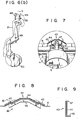
- a ribbon guide 43 has guide surface portions 44 and 45, 45 for guiding the ink ribbon 8 and the lower ends of the respective guide surface portions have a range of guide surface 46 along the lower edge of the ink ribbon 8.
- the upper ends of the respective guide surface portions have guide portions 47, ... which are outturned on the side of the ink ribbon 8.
- the guide surface portions 45 are located on both the end sides of the ribbon guide 43, i.e. on the entry and exit end sides of the ink ribbon 8, such that they are inclined in a direction of movement of the dot head 2 as shown in Fig. 8.
- the printing device so arranged will be explained below.
- the replacement, maintenance, checking, etc. of the ink ribbon 8 are carried out as follows:
- the fixing mechanism of the cutter unit of this application has been explained in connection with one embodiment as shown in Figs. 4 and 5, this invention is not restricted thereto.
- the fixing mechanism may be of such a type as shown, for example, in Figs. 10 and 11.
- In the fixing mechanism 50 use is made of a fixed lever 51 in place of the fixing screw 16.
- the fixing lever 51 is such that, as shown in Fig. 10a, engaging projections 51a and 51b are provided at both ends thereof with an insertion hole 51c and engaging holes 51d, 5ld formed in the upper surface of a plate-like body thereof.
- an engaging cutout 53a corresponding to the engaging projection 5la is provided in the forward end wall of the member 53 and an engaging cutout 53b corresponding to the engaging projection 51b is formed in the side wall portion of a supporting plate which has an insertion hole 53c.
- 54 shows a leaf plate like fixing plate having a stepped portion. As shown in Fig. 11, a fixing plate 54 has an insertion hole 54c in one side section 54a and an engaging projection 54d on the lower surface of the other side section 54b. As shown in Fig.
- the upper end of a fixing shaft 52 is inserted into the insertion hole 51c of the lever 51 and insertion hole 55c in a unit case 10a and the fixing plate 54 is inserted into an opening 55 of the unit case 10a with the side section 54b thereof located at the lower side to spring-urge the upper surface of the fixing lever 51.
- the side section 54a of the fixing plate is left at the upper side, and the upper end of the fixed shaft 52 which extends through the insertion hole 55c of the unit case 10a is inserted through the insertion hole 54c in the side portion 54a and riveted.
- the fixing lever 51 is rotatably supported on the lower surface of the unit case 10a and, when the lever 51 is rotated, the engaging projection 54d of the fixing plate 54 can be snap-fitted into either one of the engaging holes 51d, thus restricting the rotation position.
- the cutter unit 10 can be readily opened and closed, as well as readily fixed in place as in the preceding embodiment without using any fixing screw.
Landscapes
- Handling Of Sheets (AREA)
Applications Claiming Priority (2)
| Application Number | Priority Date | Filing Date | Title |
|---|---|---|---|
| JP100468/81 | 1981-06-30 | ||
| JP56100468A JPS583889A (ja) | 1981-06-30 | 1981-06-30 | プリンタ装置 |
Publications (3)
| Publication Number | Publication Date |
|---|---|
| EP0068406A2 true EP0068406A2 (de) | 1983-01-05 |
| EP0068406A3 EP0068406A3 (en) | 1985-05-15 |
| EP0068406B1 EP0068406B1 (de) | 1988-04-27 |
Family
ID=14274734
Family Applications (1)
| Application Number | Title | Priority Date | Filing Date |
|---|---|---|---|
| EP82105458A Expired EP0068406B1 (de) | 1981-06-30 | 1982-06-22 | Druck- und Schneidvorrichtung für eine Registrierkasse oder eine ähnliche Maschine |
Country Status (4)
| Country | Link |
|---|---|
| US (1) | US4451167A (de) |
| EP (1) | EP0068406B1 (de) |
| JP (1) | JPS583889A (de) |
| DE (1) | DE3278392D1 (de) |
Cited By (2)
| Publication number | Priority date | Publication date | Assignee | Title |
|---|---|---|---|---|
| GB2144373A (en) * | 1983-06-21 | 1985-03-06 | Solari & C Spa | Time clock apparatus for recording attendance data on clocking cards |
| EP0764542A1 (de) * | 1995-09-19 | 1997-03-26 | Seiko Epson Corporation | Druckvorrichtung mit automatischem Schneider |
Families Citing this family (12)
| Publication number | Priority date | Publication date | Assignee | Title |
|---|---|---|---|---|
| JPS6052378A (ja) * | 1983-09-02 | 1985-03-25 | Canon Inc | 記録紙カッタ |
| US4544293A (en) * | 1984-06-11 | 1985-10-01 | Eaton Corporation | Printer apparatus and cutting mechanism |
| JPS61102541U (de) * | 1984-12-12 | 1986-06-30 | ||
| JPS62191441U (de) * | 1986-05-28 | 1987-12-05 | ||
| TW226004B (en) * | 1993-05-10 | 1994-07-01 | Siemens Nixdorf Inf Syst | A cutting device for cutting prints in the printing machine |
| US5397880A (en) * | 1993-10-04 | 1995-03-14 | Georgilis; Steven | Taxi meter |
| KR100234589B1 (ko) * | 1995-11-21 | 1999-12-15 | 야스카와 히데아키 | 절단장치를 구비한 프린터 |
| US20090000437A1 (en) * | 2005-07-14 | 2009-01-01 | Provo Craft And Novelty, Inc. | Methods for Cutting |
| US7845259B2 (en) * | 2005-07-14 | 2010-12-07 | Provo Craft And Novelty, Inc. | Electronic paper cutting apparatus |
| US7930958B2 (en) | 2005-07-14 | 2011-04-26 | Provo Craft And Novelty, Inc. | Blade housing for electronic cutting apparatus |
| JP5001324B2 (ja) * | 2009-03-30 | 2012-08-15 | シチズンホールディングス株式会社 | プリンタ |
| US20110280999A1 (en) | 2009-12-23 | 2011-11-17 | Provo Craft And Novelty, Inc. | Foodstuff Crafting Apparatus, Components, Assembly, and Method for Utilizing the Same |
Family Cites Families (4)
| Publication number | Priority date | Publication date | Assignee | Title |
|---|---|---|---|---|
| US3850068A (en) * | 1973-07-31 | 1974-11-26 | Ncr Co | Record material cutting mechanism |
| DE2343858C3 (de) * | 1973-08-30 | 1979-05-03 | Nixdorf Computer Ag, 4790 Paderborn | Elektromechanisches Schreibwerk mit Rollenmesser |
| US4110050A (en) * | 1977-04-04 | 1978-08-29 | Texas Instruments Incorporated | Print ribbon handler |
| US4391541A (en) * | 1981-11-23 | 1983-07-05 | International Telephone & Telegraph Corp. | Mosaic printer and ribbon guide therefor |
-
1981
- 1981-06-30 JP JP56100468A patent/JPS583889A/ja active Granted
-
1982
- 1982-06-22 EP EP82105458A patent/EP0068406B1/de not_active Expired
- 1982-06-22 DE DE8282105458T patent/DE3278392D1/de not_active Expired
- 1982-06-23 US US06/391,156 patent/US4451167A/en not_active Expired - Fee Related
Cited By (4)
| Publication number | Priority date | Publication date | Assignee | Title |
|---|---|---|---|---|
| GB2144373A (en) * | 1983-06-21 | 1985-03-06 | Solari & C Spa | Time clock apparatus for recording attendance data on clocking cards |
| EP0764542A1 (de) * | 1995-09-19 | 1997-03-26 | Seiko Epson Corporation | Druckvorrichtung mit automatischem Schneider |
| US5746527A (en) * | 1995-09-19 | 1998-05-05 | Seiko Epson Corporation | Printing apparatus provided with an auto cutter |
| CN1093800C (zh) * | 1995-09-19 | 2002-11-06 | 精工爱普生株式会社 | 带有自动切纸器的打印装置 |
Also Published As
| Publication number | Publication date |
|---|---|
| EP0068406A3 (en) | 1985-05-15 |
| DE3278392D1 (en) | 1988-06-01 |
| EP0068406B1 (de) | 1988-04-27 |
| JPS6236876B2 (de) | 1987-08-10 |
| US4451167A (en) | 1984-05-29 |
| JPS583889A (ja) | 1983-01-10 |
Similar Documents
| Publication | Publication Date | Title |
|---|---|---|
| EP0068406B1 (de) | Druck- und Schneidvorrichtung für eine Registrierkasse oder eine ähnliche Maschine | |
| US6508600B1 (en) | Printer | |
| US4815875A (en) | Tape-ribbon cartridge and receiver tray with pivoted cover and cam | |
| US4815874A (en) | Thermal printer and tape-ribbon cartridge with cut-off mechanism | |
| US5181787A (en) | Thermal line printer having a rotatable head holding member | |
| US5393152A (en) | Printing device having opening and shutting mechanism | |
| KR20010062495A (ko) | 프린터 | |
| US4835619A (en) | Original reading apparatus | |
| EP0894640A2 (de) | Druckvorrichtung | |
| KR20150002536A (ko) | 서멀 프린터 | |
| JPH02299870A (ja) | プリンタ | |
| US4732068A (en) | Cutting device | |
| GB2141073A (en) | Ink ribbon feeding mechanism | |
| EP0326277A2 (de) | Gehäuse für die Baugruppen eines Druckers | |
| JP5912047B2 (ja) | サーマルプリンタ | |
| JPH0434511B2 (de) | ||
| US11926149B2 (en) | Printer | |
| JP3765397B2 (ja) | 熱転写プリンタ | |
| JP3738581B2 (ja) | テープ印刷装置 | |
| EP0286363B1 (de) | Stiftherausziehanordnung | |
| JP3345736B2 (ja) | カ−ド送り装置 | |
| JPH10258555A (ja) | ペーパーカッター装置 | |
| JP2517763Y2 (ja) | プリンタ | |
| JP2932037B2 (ja) | 紙切断装置における紙押え構造 | |
| JPH10258559A (ja) | 用紙ガイド装置 |
Legal Events
| Date | Code | Title | Description |
|---|---|---|---|
| PUAI | Public reference made under article 153(3) epc to a published international application that has entered the european phase |
Free format text: ORIGINAL CODE: 0009012 |
|
| AK | Designated contracting states |
Designated state(s): DE FR GB IT NL |
|
| PUAL | Search report despatched |
Free format text: ORIGINAL CODE: 0009013 |
|
| AK | Designated contracting states |
Designated state(s): DE FR GB IT NL |
|
| 17P | Request for examination filed |
Effective date: 19850905 |
|
| 17Q | First examination report despatched |
Effective date: 19860808 |
|
| GRAA | (expected) grant |
Free format text: ORIGINAL CODE: 0009210 |
|
| AK | Designated contracting states |
Kind code of ref document: B1 Designated state(s): DE FR GB |
|
| REF | Corresponds to: |
Ref document number: 3278392 Country of ref document: DE Date of ref document: 19880601 |
|
| ET | Fr: translation filed | ||
| PLBE | No opposition filed within time limit |
Free format text: ORIGINAL CODE: 0009261 |
|
| STAA | Information on the status of an ep patent application or granted ep patent |
Free format text: STATUS: NO OPPOSITION FILED WITHIN TIME LIMIT |
|
| 26N | No opposition filed | ||
| PGFP | Annual fee paid to national office [announced via postgrant information from national office to epo] |
Ref country code: FR Payment date: 19930514 Year of fee payment: 12 |
|
| PGFP | Annual fee paid to national office [announced via postgrant information from national office to epo] |
Ref country code: GB Payment date: 19930611 Year of fee payment: 12 |
|
| PGFP | Annual fee paid to national office [announced via postgrant information from national office to epo] |
Ref country code: DE Payment date: 19930625 Year of fee payment: 12 |
|
| PG25 | Lapsed in a contracting state [announced via postgrant information from national office to epo] |
Ref country code: GB Effective date: 19940622 |
|
| GBPC | Gb: european patent ceased through non-payment of renewal fee |
Effective date: 19940622 |
|
| PG25 | Lapsed in a contracting state [announced via postgrant information from national office to epo] |
Ref country code: FR Effective date: 19950228 |
|
| PG25 | Lapsed in a contracting state [announced via postgrant information from national office to epo] |
Ref country code: DE Effective date: 19950301 |
|
| REG | Reference to a national code |
Ref country code: FR Ref legal event code: ST |