EP0068452A2 - Maskenfokusierende Farbbildröhre - Google Patents
Maskenfokusierende Farbbildröhre Download PDFInfo
- Publication number
- EP0068452A2 EP0068452A2 EP82105584A EP82105584A EP0068452A2 EP 0068452 A2 EP0068452 A2 EP 0068452A2 EP 82105584 A EP82105584 A EP 82105584A EP 82105584 A EP82105584 A EP 82105584A EP 0068452 A2 EP0068452 A2 EP 0068452A2
- Authority
- EP
- European Patent Office
- Prior art keywords
- mask
- projections
- rows
- apertures
- shadow masks
- Prior art date
- Legal status (The legal status is an assumption and is not a legal conclusion. Google has not performed a legal analysis and makes no representation as to the accuracy of the status listed.)
- Granted
Links
Images



Classifications
-
- H—ELECTRICITY
- H01—ELECTRIC ELEMENTS
- H01J—ELECTRIC DISCHARGE TUBES OR DISCHARGE LAMPS
- H01J29/00—Details of cathode-ray tubes or of electron-beam tubes of the types covered by group H01J31/00
- H01J29/46—Arrangements of electrodes and associated parts for generating or controlling the ray or beam, e.g. electron-optical arrangement
- H01J29/80—Arrangements for controlling the ray or beam after passing the main deflection system, e.g. for post-acceleration or post-concentration, for colour switching
- H01J29/81—Arrangements for controlling the ray or beam after passing the main deflection system, e.g. for post-acceleration or post-concentration, for colour switching using shadow masks
Definitions
- the present invention relates to a mask-focusing color picture tube in which a plurality of shadow masks are opposed to a phosphor screen at a small distance therefrom and are insulated from each other to define an electrostatic lens by themselves or with a phosphor screen and, more particularly, to a shadow mask structure in such a color picture tube.
- the electron beam utility factor is as low as about 20% due to the presence of the shadow mask, and the brightness of the screen is limited. It is known that the best method to improve brightness is to increase the aperture diameter of the shadow mask and post-focus the electron beams.
- a mask-focusing color picture tube is proposed in which an electrostatic lens is formed in the vicinity of a shadow mask. Such a mask-focusing color picture tube is described in Japanese Patent Disclosure Nos. 79963/1973 and 38580/1976, Japanese Patent Publication Nos. 8261/1972 and 31265/1972, Utility Model Registration Publication No. 40681/1977, and U.S. Patent Nos. 2,971,117 and 4,112,563.
- the electrostatic lenses are formed by predetermined potential differences between a plurality of shadow masks.
- the focusing power of the electrostatic lens is weak, a great potential difference must be set between the shadow masks. Then, an arc may occured between the shadow masks, which is a serious problem.
- FIG. 1 Another type of mask-focusing color picture tube is also known in which grill-shaped shadow masks are arranged to form quadrupole lenses in the apertures of the shadow masks so as to enhance focusing force in one direction.
- the grill-shaped shadow masks are inferior in mechanical strength and formability. Therefore, such a color picture tube is also impractical.
- ridge-like projections 3 and 4 are respectively symmetrically arranged with shadow mask apertures 5 and 6 disposed therebetween. These ridge-like projections 3 and 4 oppose each other and extend in the same direction as that of phosphor stripes coated on the screen (not shown).
- lines of strong electric force are induced from the projections 4 to the projections 3. Therefore, an electrostatic lens of stronger focusing power than that obtainable without the projections may be formed.
- the deflected electron beam becomes incident on the surface of the shadow mask at a great incident angle.
- Fig. 2 shows a section, along the plane including axes X and Z, of the parts of the shadow masks 1 and 2 at a given distance on the X axis from the centers O' of the shadow masks 1 and 2.
- line l connecting the centers of apertures 5 and 6 of the shadow masks 1 and 2 coincides with a central axis m of an incident electron beam 7.
- Surfaces 8 of the shadow masks 1 and 2 form an angle ⁇ with respective to the central axis m of an incident electron beam 7.
- the central axis m of the incident electron beam 7 forms an incident angle (2 - 6) with respect to the principal plane n of an electrostatic lens 9. Therefore, with fluctuations in the focusing power of the electrostatic lens 9 due to fluctuations in the potential difference between the shadow masks 1 and 2, a central axis o of an electron beam 10 which passed through the lens 9 toward a phosphor screen 11 also fluctuates.
- This phenomenon is well known as the coma aberration of lens.
- Such fluctuations in the central axis o of the electron beam 10 which has passed through the lens 9 prevents the electron beam from bombarding on the corresponding phosphor stripe and degrades the color purity.
- the electron beam In order to solve this problem, the electron beam must be made to become incident perpendicularly to the surface of the shadow mask even at the periphery thereof.
- a mask-focusing color picture tube comprising: an evacuated envelope; means to generate a number of electron beams; a display screen comprising a large number of phosphor stripes luminescing in different colors; a plurality of masks being spaced in the predetermined distance each other, individually having a number of apertures which is arranged in rows and being disposed in the vicinity of said screen, each electron beam being assigned to phosphor stripe of a respective color through said corresponding mask aperture, wherein at least one of said plurality of shadow masks has a plurality of projections on at least one surface of said shadow mask, said projections being separated each other by the rows of said apertures and at least part of said projections being located at non-symmetrical positions with respect to the centers of the appertures.
- the present invention provides an improvement in a mask-focusing color picture tube which has shadow masks with projections formed in the vicinities of shadow mask apertures.
- color purity is generally degraded since the electron beams do not become perpendicularly incident on the parts of the shadow mask surfaces which are far in the horizontal direction from the vertical axes (vertical lines including the centers of the shadow masks) of the shadow masks.
- this degradation in the color purity is improved by horizontally offsetting the projections located at the right and left sides of the apertures in accordance with the incident angles of the electron beams.
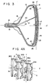
- Fig. 3 is a schematic sectional view shewing the arrangement of a mask-focusing color picture tube of the present invention.
- a funnel 13 is joined to the outer periphery of a faceplate 12, on the inner surface of which is formed a phosphor screen 11.
- a neck 14 is joined to the end of the funnel 13.
- Electron guns 15 are desposed in the neck 14.
- a deflection apparatus 16 is mounted over the outer surfaces of the funnel 13 and of the neck 14.
- a first shadow mask 17 opposes the phorphor screen 1, and a second shadow mask 18 opposes the first shadow mask 17.
- the second shadow mask 18 is mounted to the faceplate 12 by a mask frame 25 and another support means (not shown), while the first shadow mask 17 is mounted to the second shadow mask 18 through an insulating member 26.
- the phosphor screen 11 comprises phosphor stripes 23 of regularly alternating three colors coated on the inner surface of the faceplate 12, and a thin metal back layer 24 formed on the phosphor stripes 23.
- a conductive film 19 is uniformly coated on the inner surface of the funnel 13 and on part of the inner surface of the neck 14.
- three electron beams 20, 21 and 22 emitted from the electron guns 15 are deflected by the deflection apparatus 16, are selectively focused by the second and first shadow masks 18 and 17, pass through the metal back player 24, and are emitted on the respective phosphor stripes 23 which then emit light of the corresponding colors.
- the potentials of the phosphor screen 11, the conductive film 19 on the inner surface of the funnel 13, the first shadow mask 17 and the second shadow mask 18 may be set through suitable connectors (not shown) from several anode buttons (not shown) mounted on, for example, the funnel 13.
- An anode high voltage is applied to the phosphor screen 11, the conductive film 19 on the inner surface of the funnel 13 and the second shadow mask 18 at the side of the electron guns, while a voltage lower than the anode high voltage is applied to the first shadow mask 17.
- Fig. 4A is a partial enlarged view of parts, of two shadow masks according to an embodiment of the present invention, which are at a predetermined distance from the centers O' of the shadow masks on the horizontal axis (perpendicular to the phosphor stripes, -- X' axis --).
- Fig. 4B is a sectional view of the shadow masks in Fig. 4A along the plane including axes X and Z.
- ridge-like projections 33a, 30a, 34a, 34b, 35a, 35b, 36a and 36b vertically (in the direction of the phosphor stripes) extend on both surfaces of the first and second shadow masks 17 and 18 such that they sandwich arrays of apertures 31 and 32 formed in the masks 17 and 18, respectively.
- arrays of apertures and ridge-like projections are alternately formed for each of the first and second shadow masks 17 and 18.
- ridge-like projections 33a, 33b, 34a, 34b, 35a, 35b, 36a and 36b are non-symmetrical with respect to the centers of the apertures 31 or 32 interposed therebetween. This will be described in further detail with reference to the surface of the first shadow mask 17 opposing the phosphor screen 11. Referring to this surface of the first shadow mask 17, the distance from the projection 33a to the center of any aperture 31 is different from that from the projection 33b to the center of the aperture 31. The projection 33b is closer to the aperture 31 than the projection 33a. In this case, if a projection between two horizontally adjacent apertures is considered, the projection is closer to one of these apertures than the other. In other words, the projections 33a and .
- the projections 33b are offset by a predetermined distance from the centers of the horizontally adjacent apertures in the horizontal direction (direction perpendicular to the direction in which the projections extend). This applies to the projections formed on the other surface of the first shadow mask 17, and on both surfaces of the second shadow mask 18. However, the direction of offset differs from one surface to another.
- the projections 34a, 34b, 36a and 36b of the first and second shadow masks 17 and 18 on which the electron beams are incident offset toward the centers of these shadow masks.
- the degree of offset of the projections depends upon the incident angle of the electron beam. The larger the incident angle of the electron beam or the closer toward the peripheries of the shadow masks, the greater the deviation in the positions of the projections with respect to the center of the aperture. It may be easily understood that the positions of the projections need not be offset at the central part 0' of each shadow mask where the incident angle of the electron beam is close to or exactly 0°. Accordingly, a structure may be adopted wherein the measurements of offset of the projections increase toward the peripheries of the shadow masks from the vertical axes thereof (Y' axis in Fig. 3). Alternatively, another structure may be adopted wherein the measurements of offset of the projections stepwise at predetermined intervals toward the peripheries of the shadow masks from the vertical axes thereof.
- the tilt angle of the principal plane of an electrostatic lens formed between the opposing apertures of two shadow masks is determined by the plane at which the electron beam becomes incident on the aperture and the plane from which the electron beam emerges.
- the ridge-like projection 36a is located at one side of the aperture 32 in the horizontal direction, and no projection is present at the other side of the aperture 32 (the projection 36b is at a distance from the aperture 32).
- the plane of incidence of the aperture 32 corresponds to a plane 44 indicated by a dotted line which connects the pointed end of the projection 36a with the opposing flat portion in which no projection is presen-:.
- the plane of emergence of the aperture 32 corresponds to a plane 43
- the plane of incidence of the aperture 31 corresponds to a plane 42
- the plane of emergence of the aperture 31 corresponds to a plane 41, respectively.
- planes 41, 42, 43 and 44 are inclined with respect to the surfaces of the first and second shadow masks 17 and 18, and may be made perpendicular to the axis p of an electron beam 37 by suitably adjusting the heights and positions of the projections. Then, a principal plane 48 of an electrostatic lens 49 formed between the apertures of the two shadow masks can be oriented perpendicularly with respect to the axis p of the electron beam 37.
- the electron beam 37 becomes incident on the electrostatic lens 49 perpendicularly, the fluctuation in the central axis of the beam transmitted through the lens, that is, coma aberration is eliminated. Therefore, even if the focusing power of the electrostatic lens fluctuates, the central axis of the beam does not fluctuate.
- the specifications of the color picture tube of the embodiment described above are, for example, as follows.
- the mask-focusing color picture tube was of 20" 90° deflection type.
- the radius of curvature of the first and second shadow masks in the horizontal direction was about 740 mm.
- the radius of curvature of the phosphour screen in the horizontal direction was about 790 mm.
- the incident angle of the electron beams to the shadow masks was about 20° and the distance between the phosphor screen and the first shadow mask 17 was about 14.5 mm.
- the distance between the first and second shadow masks was about 0.5 mm.
- the aperture diameter of the shadow mask was 0.45 mm, and the aperture pitch (distance between the centers of the apertures) was 0.75 mm.
- the height of the ridge-like projections at the sides of the apertures was 0.10 mm.
- the positions of the ridge-like projections were horizontally offset by about 0.1 mm from the intermediate point between the two apertures sandwiching each of these projections.
- ridge-like projections which are non-symmetrical about the apertures or which are offset in their positions are formed on both surfaces of each of the two shadow masks.
- projections may be formed on one or both surfaces of only one of the two shadow masks. It is also possible to form such projections on one surface each of the two shadow masks.
- the angle formed by the principal plane of the electrostatic lens formed between the apertures of the opposing shadow masks with the axis of the electron beam may be adjustable through control of the height of the projections.
- the projections are not limited to the ridge-like projections which extend from the upper side to the lower side of the shadow mask.
- the projections may be small projections as seen in U.S.S.N. 351,882, which are independently formed on both sides of each aperture.
- the shape of the aperture need not be circular but may be elliptic or rectangular to obtain the same effects of the present invention.
- the projections extend in the same direction of the phosphor stripes, that is, the projections extend vertically, in each of the two shadow masks.
- the present invention is not limited to this.
- shadow masks of the structure may be adopted wherein the vertically extending projections as shown in Fig. 4A are formed on the surface of the screen side shadow mask facing the electron gun side shadow mask, while projections extending perpendicularly to the phosphor stripes are formed on the surface of the electron gun side shadow mask, facing the screen side shadow mask at the side of the phosphor screen.
- the projections formed on the facing surfaces of the two shadow masks extend perpendicularly to each other, and an electrostatic lens formed between the corresponding apertures is a quadrupole lens.
- the shadow masks of such a structure is shown in U.S.S.N. 351,882 in detail.
- the central axis of the electron beam does not coincide with the center of the quadrupole lens and is not subject to the uniform focusing power by the quadrupole lens. Therefore, the axis of the electron beam which has passed through the quadrupole lens fluctuates with fluctuations in the focusing power. This problem may be solved by offsetting the positions of the projections formed on the shadow mask at the periphery of the phosphor screen. This will be described below with reference to Fig. 5.
- Fig. 5 is a sectional view of side parts of shadow masks away from the centers thereof along a horizontal axis.
- ridge-like projections 53 are formed on the surface of a first shadow mask 57 facing a second shadow mask 58 to be non-symmetrical about an aperture 51 or extend vertically at positions offset from the center of the aperture 51 toward the central part of the first shadow mask 57.
- ridge-like projections 54 extend horizontally on the surface of the second shadow mask 58 facing the first shadow maks 57.
- the middle point between the projections 53 or a center 60 of the electrostatic lens is moved from the center of the aperture 51 in the same direction of offset of the projections.
- an electron beam 61 is subjected to focusing powers 63 and 64 which are substantially equal to each other.
- a central axis 62 of the electron beam 61 which has passed through the apertures 51 and 52 may not fluctuate with fluctuations in the potential difference between the shadow masks 57 and 58 or in the intensity of the electrostatic lens.
- the horizontally extending ridge-like projections 54 formed on the second shadow mask 58 are symmetrical about the center of each aperture.
- these ridge-like projections 54 may be increasingly vertically offset toward the upper and lower sides of the shadow mask from the horizontal axis thereof as in the case of the horizontally offsetting ridge-like projections 53 formed on the shadow mask 57.
- Fig. 6 shows an embodiment of shadow masks wherein both of the horizontally and vertically extending projections are non-symmetrical about the centers of the apertures or are offset therefrom.
- the shadow masks structure showed in Fig. 6 is at some distance from the center O' of the shadow mask in the direction of horizontal and in the direction of vertical. Referring to Fig.
- ridge-like projections 73 formed on the surface of a first shadow mask 77 opposing a second shadow mask 78 as well as ridge-like projections 74 formed on the surface of the second shadow mask 78 opposing the first shadow mask 77 are both non-symmetrically about the centers of apertures 71 and 72 or are deviated therefrom.
- the projections 74 are deviated toward the upper and lower sides of the shadow mask unlike the direction of deviation of the projections 73.
- the shadow masks shown in Fig. 6 may be manufactured by coating one surface of an iron plate with a mask pattern for apertures and another surface of the iron plate with a stripe-shaped mask pattern which is non-symmetrical about the centers of these apertures, and then etching the iron plate through these mask patterns.
- the present invention has been described with reference to the embodiments of mask-focusing color picture tubes having two shadow masks. However, the present invention is similarly applicable to mask-focusing color picture tubes having a plurality of shadow masks.
Landscapes
- Electrodes For Cathode-Ray Tubes (AREA)
Applications Claiming Priority (2)
| Application Number | Priority Date | Filing Date | Title |
|---|---|---|---|
| JP98200/81 | 1981-06-26 | ||
| JP56098200A JPS581955A (ja) | 1981-06-26 | 1981-06-26 | マスク集束型カラ−受像管 |
Publications (3)
| Publication Number | Publication Date |
|---|---|
| EP0068452A2 true EP0068452A2 (de) | 1983-01-05 |
| EP0068452A3 EP0068452A3 (en) | 1983-05-25 |
| EP0068452B1 EP0068452B1 (de) | 1986-02-05 |
Family
ID=14213356
Family Applications (1)
| Application Number | Title | Priority Date | Filing Date |
|---|---|---|---|
| EP82105584A Expired EP0068452B1 (de) | 1981-06-26 | 1982-06-24 | Maskenfokusierende Farbbildröhre |
Country Status (4)
| Country | Link |
|---|---|
| US (1) | US4503355A (de) |
| EP (1) | EP0068452B1 (de) |
| JP (1) | JPS581955A (de) |
| DE (1) | DE3268941D1 (de) |
Cited By (1)
| Publication number | Priority date | Publication date | Assignee | Title |
|---|---|---|---|---|
| DE3328884A1 (de) * | 1982-08-11 | 1984-02-16 | RCA Corp., 10020 New York, N.Y. | Kathodenstrahlroehre mit vierpolig fokussierender farbwahleinrichtung |
Families Citing this family (2)
| Publication number | Priority date | Publication date | Assignee | Title |
|---|---|---|---|---|
| JPS57163955A (en) * | 1981-02-25 | 1982-10-08 | Toshiba Corp | Mask focusing type color picture tube |
| BE1007430A3 (nl) * | 1993-08-02 | 1995-06-13 | Philips Electronics Nv | Kleurenkathodestraalbuis en beeldweergeefinrichting. |
Family Cites Families (10)
| Publication number | Priority date | Publication date | Assignee | Title |
|---|---|---|---|---|
| US2971117A (en) * | 1956-03-01 | 1961-02-07 | Rca Corp | Color-kinescopes, etc. |
| US3668002A (en) * | 1968-07-01 | 1972-06-06 | Hitachi Ltd | Shadow mask having focusing function and method of making same |
| US3502942A (en) * | 1968-10-24 | 1970-03-24 | Zenith Radio Corp | Post-deflection-focus cathode-ray tube |
| US3944867A (en) * | 1974-03-15 | 1976-03-16 | Zenith Radio Corporation | Shadow mask having ribs bounding rectangular apertures |
| US4059781A (en) * | 1974-07-17 | 1977-11-22 | U.S. Philips Corporation | Shadow mask each aperture of which is defined by a quadrupolar lens |
| NL7600420A (nl) * | 1976-01-16 | 1977-07-19 | Philips Nv | Elektrische ontladingsinrichting. |
| NL7600419A (nl) * | 1976-01-16 | 1977-07-19 | Philips Nv | Kleurenbeeldbuis en werkwijze ter vervaardiging daarvan. |
| US4112563A (en) * | 1977-01-13 | 1978-09-12 | U.S. Philips Corporation | Color display tube and method of manufacturing same |
| NL7909232A (nl) * | 1979-12-21 | 1981-07-16 | Philips Nv | Kathodenstraalbuis. |
| JPS57163955A (en) * | 1981-02-25 | 1982-10-08 | Toshiba Corp | Mask focusing type color picture tube |
-
1981
- 1981-06-26 JP JP56098200A patent/JPS581955A/ja active Granted
-
1982
- 1982-06-24 EP EP82105584A patent/EP0068452B1/de not_active Expired
- 1982-06-24 DE DE8282105584T patent/DE3268941D1/de not_active Expired
- 1982-06-25 US US06/392,244 patent/US4503355A/en not_active Expired - Fee Related
Cited By (1)
| Publication number | Priority date | Publication date | Assignee | Title |
|---|---|---|---|---|
| DE3328884A1 (de) * | 1982-08-11 | 1984-02-16 | RCA Corp., 10020 New York, N.Y. | Kathodenstrahlroehre mit vierpolig fokussierender farbwahleinrichtung |
Also Published As
| Publication number | Publication date |
|---|---|
| US4503355A (en) | 1985-03-05 |
| EP0068452A3 (en) | 1983-05-25 |
| JPS581955A (ja) | 1983-01-07 |
| EP0068452B1 (de) | 1986-02-05 |
| JPH0226338B2 (de) | 1990-06-08 |
| DE3268941D1 (en) | 1986-03-20 |
Similar Documents
| Publication | Publication Date | Title |
|---|---|---|
| US2957106A (en) | Plural beam gun | |
| US4935663A (en) | Electron gun assembly for color cathode ray tube apparatus | |
| CA1212144A (en) | Cathode-ray tube having an asymmetric slot formed in a screen grid electrode of an inline electron gun | |
| PL117769B1 (en) | Colour picture tube | |
| JP2711553B2 (ja) | カラーディスプレイ管及びそれに使用する電子銃 | |
| US5932958A (en) | Color cathode ray tube having beam passageways with barrel-like segment | |
| EP0058992B1 (de) | Farbbildröhre mit Fokussierungsmaske | |
| US4503355A (en) | Mask-focusing color picture tube | |
| US5942844A (en) | Color cathode ray tube having a small neck diameter | |
| EP0452789B1 (de) | Farbbildröhre mit "inline" Elektronenkanone mit Fokusjustierung | |
| JPH03233839A (ja) | カラー陰極線管 | |
| CA1228108A (en) | Cathode ray tube with helical lens | |
| GB2175743A (en) | Cathode-ray tube electron gun having improved screen grid | |
| EP0501584B1 (de) | Kathodenstrahlröhre mit Elektronenstrahlerzeugersystem mit planparalleler Optik | |
| GB2314966A (en) | Electron gun for colour cathode ray tube | |
| CA1137153A (en) | Means and method for beam spot distortion in tv picture tubes | |
| US4701665A (en) | Color cathode-ray tube | |
| JP3742122B2 (ja) | カラー受像管用インライン型電子銃 | |
| GB2135503A (en) | Accelerating and scan expansion electron lens system | |
| EP1361596B1 (de) | Inline-Elektronenkanone und Farbbildröhre mit selbiger | |
| EP0226145A2 (de) | Elektronenkanone | |
| US6628061B2 (en) | Electron gun for cathode ray tube | |
| US3619687A (en) | Color tv tube having curved convergence deflection plates | |
| US5243254A (en) | Electron gun for color picture tube | |
| KR0129381Y1 (ko) | 칼라수상관용 전자총 |
Legal Events
| Date | Code | Title | Description |
|---|---|---|---|
| PUAI | Public reference made under article 153(3) epc to a published international application that has entered the european phase |
Free format text: ORIGINAL CODE: 0009012 |
|
| 17P | Request for examination filed |
Effective date: 19820721 |
|
| AK | Designated contracting states |
Designated state(s): DE FR GB |
|
| PUAL | Search report despatched |
Free format text: ORIGINAL CODE: 0009013 |
|
| AK | Designated contracting states |
Designated state(s): DE FR GB |
|
| RAP1 | Party data changed (applicant data changed or rights of an application transferred) |
Owner name: KABUSHIKI KAISHA TOSHIBA |
|
| GRAA | (expected) grant |
Free format text: ORIGINAL CODE: 0009210 |
|
| AK | Designated contracting states |
Designated state(s): DE FR GB |
|
| ET | Fr: translation filed | ||
| REF | Corresponds to: |
Ref document number: 3268941 Country of ref document: DE Date of ref document: 19860320 |
|
| PLBE | No opposition filed within time limit |
Free format text: ORIGINAL CODE: 0009261 |
|
| STAA | Information on the status of an ep patent application or granted ep patent |
Free format text: STATUS: NO OPPOSITION FILED WITHIN TIME LIMIT |
|
| REG | Reference to a national code |
Ref country code: GB Ref legal event code: 746 |
|
| 26N | No opposition filed | ||
| PGFP | Annual fee paid to national office [announced via postgrant information from national office to epo] |
Ref country code: FR Payment date: 19940609 Year of fee payment: 13 |
|
| PGFP | Annual fee paid to national office [announced via postgrant information from national office to epo] |
Ref country code: GB Payment date: 19940615 Year of fee payment: 13 |
|
| PGFP | Annual fee paid to national office [announced via postgrant information from national office to epo] |
Ref country code: DE Payment date: 19940622 Year of fee payment: 13 |
|
| PG25 | Lapsed in a contracting state [announced via postgrant information from national office to epo] |
Ref country code: GB Effective date: 19950624 |
|
| GBPC | Gb: european patent ceased through non-payment of renewal fee |
Effective date: 19950624 |
|
| PG25 | Lapsed in a contracting state [announced via postgrant information from national office to epo] |
Ref country code: FR Effective date: 19960229 |
|
| PG25 | Lapsed in a contracting state [announced via postgrant information from national office to epo] |
Ref country code: DE Effective date: 19960301 |
|
| REG | Reference to a national code |
Ref country code: FR Ref legal event code: ST |