EP0068455A1 - Socken mit einer Halteeinrichtung - Google Patents
Socken mit einer Halteeinrichtung Download PDFInfo
- Publication number
- EP0068455A1 EP0068455A1 EP82105619A EP82105619A EP0068455A1 EP 0068455 A1 EP0068455 A1 EP 0068455A1 EP 82105619 A EP82105619 A EP 82105619A EP 82105619 A EP82105619 A EP 82105619A EP 0068455 A1 EP0068455 A1 EP 0068455A1
- Authority
- EP
- European Patent Office
- Prior art keywords
- sock
- holding elements
- holding
- sock according
- shaft
- Prior art date
- Legal status (The legal status is an assumption and is not a legal conclusion. Google has not performed a legal analysis and makes no representation as to the accuracy of the status listed.)
- Granted
Links
- 230000000694 effects Effects 0.000 claims description 4
- 229920001971 elastomer Polymers 0.000 claims description 2
- 239000000806 elastomer Substances 0.000 claims description 2
- 230000002093 peripheral effect Effects 0.000 abstract 1
- 239000000463 material Substances 0.000 description 7
- 238000004519 manufacturing process Methods 0.000 description 3
- 230000017531 blood circulation Effects 0.000 description 2
- 210000002683 foot Anatomy 0.000 description 2
- 239000000758 substrate Substances 0.000 description 2
- 239000004753 textile Substances 0.000 description 2
- 238000004873 anchoring Methods 0.000 description 1
- 210000003423 ankle Anatomy 0.000 description 1
- 239000004744 fabric Substances 0.000 description 1
- 238000005457 optimization Methods 0.000 description 1
Images
Classifications
-
- D—TEXTILES; PAPER
- D04—BRAIDING; LACE-MAKING; KNITTING; TRIMMINGS; NON-WOVEN FABRICS
- D04B—KNITTING
- D04B1/00—Weft knitting processes for the production of fabrics or articles not dependent on the use of particular machines; Fabrics or articles defined by such processes
- D04B1/22—Weft knitting processes for the production of fabrics or articles not dependent on the use of particular machines; Fabrics or articles defined by such processes specially adapted for knitting goods of particular configuration
- D04B1/24—Weft knitting processes for the production of fabrics or articles not dependent on the use of particular machines; Fabrics or articles defined by such processes specially adapted for knitting goods of particular configuration wearing apparel
- D04B1/26—Weft knitting processes for the production of fabrics or articles not dependent on the use of particular machines; Fabrics or articles defined by such processes specially adapted for knitting goods of particular configuration wearing apparel stockings
-
- A—HUMAN NECESSITIES
- A41—WEARING APPAREL
- A41B—SHIRTS; UNDERWEAR; BABY LINEN; HANDKERCHIEFS
- A41B11/00—Hosiery; Panti-hose
- A41B11/02—Reinforcements
- A41B11/04—Reinforcements of the stocking top
-
- A—HUMAN NECESSITIES
- A41—WEARING APPAREL
- A41B—SHIRTS; UNDERWEAR; BABY LINEN; HANDKERCHIEFS
- A41B11/00—Hosiery; Panti-hose
- A41B11/12—Means at the upper end to keep the stockings up
- A41B11/126—Means at the upper end to keep the stockings up having friction increasing means
- A41B11/128—Means at the upper end to keep the stockings up having friction increasing means in discontinuous form
Definitions
- the invention relates to a sock with a holding device for maintaining its position on the wearer's leg.
- socks refers to short stockings that have an ankle or calf-length stocking. Most socks end in the wearer's leg, which widens upwards. As a result, holding the sock in its stretched position is not guaranteed without special measures.
- Various solutions have become known as holding devices. The solution often used in the past, using sock holders, is increasingly being replaced by a solution in which the sock shaft is given a special shape. An embodiment is known in which the sock shaft is shaped in accordance with the leg area of the wearer.
- the invention has for its object to design a sock of the type described above so that the disadvantages of the known holding devices are avoided and a tight fit of the sock shaft on the leg part can be ensured without a special shape of the sock shaft or the application which complicates the manufacture a portion of higher elasticity constricting the leg area would be required.
- This object is achieved according to the invention in that flexible and curved holding elements extending in the circumferential direction are arranged on the two-sided surface of a sock part. It is thereby achieved that the holding elements can follow changes in circumference with corresponding changes in shape, so that repeated tightening of the sock shaft is achieved on the leg circumference.
- the holding elements are expediently shaped in such a way that they have a convex curvature directed towards the foot.
- the sock shown in Fig. 1 corresponds to a known, often executed sock shape, which are mainly produced as a calf-length men's sock as knitted or crocheted.
- a collar 3 is arranged at the upper end of the sock shaft 2. If the sock is not worn, the waistband 3 narrows because it is designed as a section of increased elasticity.
- holding elements 4 which are arranged one above the other in some rows, for example.
- the holding elements 4 do not need to lie at the point shown, but this part can also be placed in the collar 3. Otherwise it would also be possible to provide the entire sock shaft 2 with holding elements 4 or to arrange the holding elements 4 in some parts which are separated from one another by spacing.
- the holding elements 4 are flexible and curved threads that extend in the circumferential direction. These are anchored in a manner not shown in the material of the sock shaft 2. Anchoring can be done in different ways. In the case of a knitted or knitted sock shaft, it is expedient to introduce the holding elements 4, which are designed as threads, into the knitted or knitted fabric with the manufacture of the shaft. It may be expedient here to hold the holding elements 4 in Arrange rows 5 one above the other, the holding elements 4 of a row 5 consisting of a single thread.
- the holding elements 4 can form a convex loop directed towards the foot, as shown in FIG. 2.
- the holding elements 4 can form an approximate circular arc.
- the bow height h can be selected in a relatively wide range and can be approximately 0.3-1.5 times the length 1 of the holding element 4 when the sock is worn. This means that, depending on the stretch of the sock on the leg, the arch height h in the unworn state can be greater than the specified value.
- the holding elements 4 described above achieve the permanently tight contact of the sock shaft 2 with the leg area of the wearer without any unpleasant side effects.
- the annoying constriction of the blood circulation can also be avoided by means of a collar 3 with great spring force.
- How this tightening of the sock shaft 2 comes about can only be guessed at. It seems that the constant changes in the circumference of the leg area surrounded by the sock shaft 2 result in stretching and thus straightening of the holding elements. When the circumference of the leg part is reduced, the straight holding element 4 apparently no longer completely returns to its original position. These differences are presumably very small, but they are sufficient to achieve the desired tight fit of the sock shaft 2 on the leg area.
- the holding elements 4 used as threads can themselves have an additional extensibility by forming the Holding elements 4 elastic threads, for example threads with a stretch effect or textile-covered elastomer threads, can be used.
- the holding elements 4 of the individual rows 5 do not have to lie one below the other. You can also, e.g. be offset in the side and / or in height.
- the holding device described in the form of a number of holding elements 4 represents a surprisingly simple and effective solution. It can be used irrespective of the material of the sock, the material of the holding elements 4 also being able to be adapted to the different materials both in shape and in material. The number of holding elements used also depends on the material and the manufacture of the sock.
- the holding device can be used wherever textile substrates worn on the body are to be held taut, for example in bandages for bandages, camisoles or the like.
- the holding elements are to be arranged so that the clamping effect occurs in the desired direction, depending on the processing and the material of the holding elements With appropriate optimization, the arch height of the textile substrate can slightly exceed the specified width, e.g. 4.0 times the length l.
Landscapes
- Engineering & Computer Science (AREA)
- Textile Engineering (AREA)
- Socks And Pantyhose (AREA)
- Treatment Of Fiber Materials (AREA)
- Knitting Machines (AREA)
- Adornments (AREA)
- Holders For Apparel And Elements Relating To Apparel (AREA)
Abstract
Description
- Die Erfindung betrifft eine Socke mit einer Halteeinrichtung zur Einhaltung ihrer Lage am Bein des Trägers.
- Unter dem Begriff "Socke" werden hier kurze Strümpfe bezeichnet, die etwa einen knöchel- oder wadenlangen Strumpfschaft aufweisen. Die meisten Socken enden in einer Beinpartie des Trägers, die sich nach oben erweitert. Dies hat zur Folge, dass das Festhalten des Sockens in seiner gestreckten Lage nicht ohne besondere Massnahmen gewährleistet ist. Als Halteeinrichtungen sind verschiedene Lösungen bekannt geworden. Die früher häufig angewendete Lösung unter Verwendung von Sockenhaltern wird mehr und mehr durch eine Lösung ersetzt, bei der dem Sockenschaft eine besondere Formgebung erteilt wird. Bekannt ist eine Ausführungsform, bei der der Sockenschaft entsprechend der Beinpartie des Trägers geformt ist. Damit wird zwar ein gutes Anliegen des Sockenschaftes an die Beinpartie des Trägers erreicht, jedoch kann ein Abgleiten des Sockenschaftes nicht verhindert werden; beim Gehen ist das Abwärtsrutschen des Sockenschaftes nicht zu vermeiden, und es bilden sich unschöne Falten. Eine weitere, viel verwendete Halteeinrichtung bei Socken besteht darin, dass am Ende des Schaftbundes eine Bundpartie vorgesehen wird, die eine stärkere Elastizität aufweist als der übrige Teil des Sockenschaftes. Der Nachteil dieser Ausführung besteht darin, dass die Partie stärkerer Elastizität bzw. stärkerer Federwirkung tiefer in die Beinpartie des Trägers einschneidet und damit die Blutzirkulation in der Beinpartie behindert; für Personen mit empfindlichen Beinpartien können solche Socken unangenehm oder sogar schmerzhaft sein. Auch wenn man von diesem Nachteil absieht, ist auch diese Halteeinrichtung keineswegs in der Lage, den Sockenschaft straff an der Beinpartie des Trägers, insbesondere beim Gehen, zu halten.
- Der Erfindung liegt die Aufgabe zugrunde, eine Socke der eingangs beschriebenen Art so auszugestalten, dass die Nachteile der bekannten Halteeinrichtungen vermieden werden und ein straffes Anliegen des Sockenschaftes an der Beinpartie gewährleistet werden kann, ohne dass eine die Fabrikation erschwerende besondere Formgebung des Sockenschaftes oder die Anwendung einer die Beinpartie einschnürenden Partie höherer Elastizität erforderlich wäre.
- Diese Aufgabe wird gemäss der Erfindung dadurch gelöst, dass auf der beinseitigen Oberfläche eines Sockenteils sich in Umfangsrichtung erstreckende flexible und gebogene Halteelemente angeordnet sind. Dadurch wird erreicht, dass die Halteelemente Umfangsänderungen mit entsprechenden Formänderungen folgen können, so dass damit am Beinumfang ein wiederholtes Straffen des Sockenschaftes erzielt wird. Zweckmässig sind hierbei die Halteelemente derart geformt, dass sie eine fusswärts gerichtete konvexe Wölbung aufweisen.
- Die Erfindung ist in der Zeichnung in einem Ausführungsbeispiel dargestellt und nachfolgend beschrieben. Es zeigen:
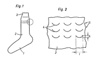
- Fig. 1 eine schematisch dargestellte Ansicht einer Socke und
- Fig. 2 einen Ausschnitt aus der in Fig. 1 markierten Partie des Sockenschaftes in vergrösserter Darstellung.
- Die in Fig. l dargestellte Socke entspricht einer bekannten, vielfach ausgeführten Sockenform, die hauptsächlich als wadenlange Herrensocke als Gestricke oder Gewirke hergestellt werden. Am oberen Ende des Sockenschaftes 2 ist ein Bund 3 angeordnet. Wird die Socke nicht getragen, verengt sich der Bund 3, da er als Partie erhöhter Elastizität ausgebildet ist.
- Unterhalb des Bundes 3 sind als Punkte angeordnete Halteelemente 4 vorgesehen, die beispielsweise in einigen Reihen übereinander angeordnet sind. Die Halteelemente 4 brauchen nicht an der eingezeichneten Stelle zu liegen, vielmehr kann diese Partie ebenfalls in den Bund 3 gelegt werden. Im übrigen wäre es auch möglich, den gesamten Sockenschaft 2 mit Halteelementen 4 zu versehen oder die Halteelemente 4 in einigen, durch Abstände voneinander getrennten Partien anzuordnen.
- Wie aus Fig. 2 ersichtlich ist, die eine vergrösserte Darstellung der in Fig. 1 eingerahmten Partie zeigt, sind die Halteelemente 4 sich in Umfangsrichtung erstreckende flexible und gebogene Fäden. Diese sind in nicht näher dargestellter Weise in dem Material des Sockenschaftes 2 verankert. Die Verankerung kann in verschiedener Weise erfolgen. Bei einem gewirkten oder gestrickten Sockenschaft ist es zweckmässig, die als Fäden ausgebildeten Halteelemente 4 mit der Herstellung des Schaftes in das Gestricke oder Gewirke einzubringen. Hierbei kann es zweckmässig sein, die Halteelemente 4 in übereinanderliegenden Reihen 5 anzuordnen, wobei die Halteelemente 4 einer Reihe 5 aus einem einzigen Faden bestehen.
- Wesentlich ist, dass die Halteelemente 4 eine fusswärts gerichtete konvexe Schlaufe bilden, wie dies Fig. 2 zeigt. Die Halteelemente 4 können hierbei einen angenäherten Kreisbogen bilden. Die Bogenhöhe h kann in verhältnismässig weitem Bereich gewählt werden und kann beim Tragen der Socke etwa das 0,3 - 1,5-fache der Länge 1 des Halteelementes 4 betragen. Dies bedeutet, dass je nach der Dehnung der Socke am Bein die Bogenhöhe h in ungetragenem Zustand grösser als der angegebene Wert sein kann.
- Es hat sich nun überraschend gezeigt, dass durch die vorstehend beschriebenen Halteelemente 4 das dauernd straffe Anliegen des Sockenschaftes 2 an die Beinpartie des Trägers erreicht wird, ohne dass unangenehme Nebenwirkungen auftreten würden. Insbesondere kann auch das lästige Abschnüren der Blutzirkulation durch einen Schaftbund 3 mit grosser Federkraft vermieden werden. Wie dieses Straffen des Sockenschaftes 2 zustandekommt, kann nur vermutet werden. Es scheint, dass durch die dauernden Veränderungen des Umfangs der vom Sockenschaft 2 umgebenen Beinpartie ein Strecken und damit ein Geraderichten der Halteelemente zustandekommt. Bei Verminderung des Umfangs der Beinpartie geht offenbar das geradegerichtete Halteelement 4 nicht mehr ganz in seine ursprüngliche Lage zurück. Diese Unterschiede sind vermutlich sehr klein, doch reichen sie völlig aus, um das gewünschte straffe Anliegen des Sockenschaftes 2 an der Beinpartie zu erreichen.
- Die als Fäden verwendeten Halteelemente 4 können selbst eine zusätzliche Dehnbarkeit aufweisen, indem für die Bildung der Halteelemente 4 elastische Fäden, z.B. Fäden mit Stretch-Wirkung oder textilumsponnene Elastomerfäden, verwendet werden.
- Die Halteelemente 4 der einzelnen Reihen 5 brauchen nicht untereinanderzuliegen. Sie können auch, z.B. in der Seite und/oder in der Höhe, versetzt angeordnet sein.
- Damit die gewünschte Lage der Halteelemente 4 unabhängig von der Art des Anziehens der Socke eingehalten wird, kann es zweckmässig sein, die Halteelemente 4 einer formstabilisierenden Behandlung zu unterziehen. Das Straffhalten des Sockenschaftes 2 tritt jedoch auch auf, wenn eine solche Behandlung nicht vorgenommen wird. Diese dient mehr dem praktischen Zweck, die Lageanordnung der Halteelemente 4 auch bei unsachgemässer Behandlung der Socke zu gewährleisten.
- Die beschriebene Halteeinrichtung in Form einer Anzahl Halteelementen 4 stellt eine überraschend einfache und wirksame Lösung dar. Sie kann unabhängig vom Material der Socke verwendet werden, wobei auch das Material der Halteelemente 4 den verschiedenen Materialien sowohl in der Form als auch im Material angepasst werden kann. Die Zahl der verwendeten Halteelemente richtet sich ebenfalls nach dem Material und der Herstellung der Socke.
- Die Halteeinrichtung kann überall dort angewandt werden, wo auf dem Körper getragene textile Substrate gespannt gehalten werden sollen, z.B. bei Binden für Verbände, Leibchen o.dgl. Die Halteelemente sind hierbei so anzuordnen, dass die Spannwirkung in der gewünschten Richtung auftritt, je nach der Verarbeitung und dem Material des die Halteelemente aufweisenden textilen Substrats kann die Bogenhöhe bei entsprechender Optimierung die angegebene Weite etwas überschreiten, z.B. das 4,0 fache der Länge ℓ.
Claims (9)
Priority Applications (1)
| Application Number | Priority Date | Filing Date | Title |
|---|---|---|---|
| AT82105619T ATE26907T1 (de) | 1981-06-29 | 1982-06-25 | Socken mit einer halteeinrichtung. |
Applications Claiming Priority (2)
| Application Number | Priority Date | Filing Date | Title |
|---|---|---|---|
| CH4280/81A CH659175A5 (de) | 1981-06-29 | 1981-06-29 | Socken mit einer halteeinrichtung. |
| CH4280/81 | 1981-06-29 |
Publications (2)
| Publication Number | Publication Date |
|---|---|
| EP0068455A1 true EP0068455A1 (de) | 1983-01-05 |
| EP0068455B1 EP0068455B1 (de) | 1987-05-06 |
Family
ID=4273168
Family Applications (1)
| Application Number | Title | Priority Date | Filing Date |
|---|---|---|---|
| EP82105619A Expired EP0068455B1 (de) | 1981-06-29 | 1982-06-25 | Socken mit einer Halteeinrichtung |
Country Status (5)
| Country | Link |
|---|---|
| EP (1) | EP0068455B1 (de) |
| JP (1) | JPS588101A (de) |
| AT (1) | ATE26907T1 (de) |
| CH (1) | CH659175A5 (de) |
| DE (1) | DE3276211D1 (de) |
Citations (6)
| Publication number | Priority date | Publication date | Assignee | Title |
|---|---|---|---|---|
| CH151656A (de) * | 1930-06-12 | 1931-12-31 | Philipp Weil & Cie | Strumpf oder Socken mit Befestigungsrand. |
| FR963871A (de) * | 1950-07-24 | |||
| US2977782A (en) * | 1959-04-29 | 1961-04-04 | Hanes Hosiery Mills Company | Knitted fabric |
| FR1287120A (fr) * | 1961-04-19 | 1962-03-09 | Perfectionnement aux chaussettes | |
| US3249110A (en) * | 1964-02-19 | 1966-05-03 | Beautiful Bryans Inc | Combination supporting garment and hosiery |
| GB2044815A (en) * | 1979-03-09 | 1980-10-22 | Pschorr R | A knitted stocking and process for producing it |
Family Cites Families (1)
| Publication number | Priority date | Publication date | Assignee | Title |
|---|---|---|---|---|
| JPS512094Y2 (de) * | 1971-01-14 | 1976-01-22 |
-
1981
- 1981-06-29 CH CH4280/81A patent/CH659175A5/de not_active IP Right Cessation
-
1982
- 1982-06-25 DE DE8282105619T patent/DE3276211D1/de not_active Expired
- 1982-06-25 AT AT82105619T patent/ATE26907T1/de not_active IP Right Cessation
- 1982-06-25 EP EP82105619A patent/EP0068455B1/de not_active Expired
- 1982-06-29 JP JP57110899A patent/JPS588101A/ja active Pending
Patent Citations (6)
| Publication number | Priority date | Publication date | Assignee | Title |
|---|---|---|---|---|
| FR963871A (de) * | 1950-07-24 | |||
| CH151656A (de) * | 1930-06-12 | 1931-12-31 | Philipp Weil & Cie | Strumpf oder Socken mit Befestigungsrand. |
| US2977782A (en) * | 1959-04-29 | 1961-04-04 | Hanes Hosiery Mills Company | Knitted fabric |
| FR1287120A (fr) * | 1961-04-19 | 1962-03-09 | Perfectionnement aux chaussettes | |
| US3249110A (en) * | 1964-02-19 | 1966-05-03 | Beautiful Bryans Inc | Combination supporting garment and hosiery |
| GB2044815A (en) * | 1979-03-09 | 1980-10-22 | Pschorr R | A knitted stocking and process for producing it |
Also Published As
| Publication number | Publication date |
|---|---|
| JPS588101A (ja) | 1983-01-18 |
| CH659175A5 (de) | 1987-01-15 |
| EP0068455B1 (de) | 1987-05-06 |
| ATE26907T1 (de) | 1987-05-15 |
| DE3276211D1 (en) | 1987-06-11 |
Similar Documents
| Publication | Publication Date | Title |
|---|---|---|
| DE69400773T2 (de) | Medizinische Kompressionseinrichtung für ein Bein oder einen Arm | |
| DE2056271A1 (de) | Bandage zur Fixierung von Wundver banden | |
| CH712938B1 (de) | Kompressionskleidungsstück. | |
| DE69315086T2 (de) | Bandage | |
| DE69710600T2 (de) | Mittel zur haltung von strümpfen oder strümpfhosen an hüften und so hergestellte strümpfhosen | |
| EP0068455B1 (de) | Socken mit einer Halteeinrichtung | |
| DE662633C (de) | Auf der flachen Kulierwirkmaschine formgerecht gearbeiteter glatter Strumpf | |
| AT527162B1 (de) | Vorrichtung zum verkürzen einer randkante von textilien | |
| DE666955C (de) | Strumpfoberteil | |
| DE3205109C2 (de) | Zweiteilige Strumpfwarenkombination | |
| CH495717A (de) | Formfixiertes Hüftstrumpfpaar | |
| DE816231C (de) | Socke fuer Herren und Damen | |
| DE975881C (de) | Kettenwirkware mit Gummikettenfaeden | |
| DE182899C (de) | ||
| DE7032243U (de) | Strumpfhose fuer schwangere. | |
| DE414177C (de) | Als Abschluss der Socke oder des Strumpfes dienender Halter | |
| DE659581C (de) | Langer Damenstrumpf mit aus einem Gewebeband bestehendem Randabschluss | |
| DE8900936U1 (de) | Stützbandagen für Gliedmaßen und/oder Gelenke | |
| AT206561B (de) | Hochelastischer Strickstoff | |
| DE2029933A1 (en) | Knitted tights stretch panties - with increased longitudinal stretch around the waist band | |
| DE2041764A1 (de) | Damenlangbeinhose | |
| DE845632C (de) | Befestigungsvorrichtung fuer fertige Krawatten | |
| EP1051923A2 (de) | Elastiches Band und Verfahren zu dessen Herstellung | |
| EP3747292A1 (de) | Hemd umfassend ein vorderteil, ein rückenteil, zwei ärmel und einen kragen | |
| DE8513619U1 (de) | Medizinischer, schenkellanger Strumpf |
Legal Events
| Date | Code | Title | Description |
|---|---|---|---|
| PUAI | Public reference made under article 153(3) epc to a published international application that has entered the european phase |
Free format text: ORIGINAL CODE: 0009012 |
|
| AK | Designated contracting states |
Designated state(s): AT BE CH DE FR GB IT LI LU NL SE |
|
| 17P | Request for examination filed |
Effective date: 19830625 |
|
| GRAA | (expected) grant |
Free format text: ORIGINAL CODE: 0009210 |
|
| AK | Designated contracting states |
Kind code of ref document: B1 Designated state(s): AT BE CH DE FR GB IT LI LU NL SE |
|
| REF | Corresponds to: |
Ref document number: 26907 Country of ref document: AT Date of ref document: 19870515 Kind code of ref document: T |
|
| ITF | It: translation for a ep patent filed | ||
| REF | Corresponds to: |
Ref document number: 3276211 Country of ref document: DE Date of ref document: 19870611 |
|
| ET | Fr: translation filed | ||
| PLBE | No opposition filed within time limit |
Free format text: ORIGINAL CODE: 0009261 |
|
| STAA | Information on the status of an ep patent application or granted ep patent |
Free format text: STATUS: NO OPPOSITION FILED WITHIN TIME LIMIT |
|
| 26N | No opposition filed | ||
| ITTA | It: last paid annual fee | ||
| EPTA | Lu: last paid annual fee | ||
| EAL | Se: european patent in force in sweden |
Ref document number: 82105619.9 |
|
| PGFP | Annual fee paid to national office [announced via postgrant information from national office to epo] |
Ref country code: CH Payment date: 19980911 Year of fee payment: 17 |
|
| PGFP | Annual fee paid to national office [announced via postgrant information from national office to epo] |
Ref country code: GB Payment date: 19981210 Year of fee payment: 17 |
|
| PGFP | Annual fee paid to national office [announced via postgrant information from national office to epo] |
Ref country code: AT Payment date: 19981211 Year of fee payment: 17 |
|
| PGFP | Annual fee paid to national office [announced via postgrant information from national office to epo] |
Ref country code: SE Payment date: 19981214 Year of fee payment: 17 |
|
| PGFP | Annual fee paid to national office [announced via postgrant information from national office to epo] |
Ref country code: LU Payment date: 19981215 Year of fee payment: 17 |
|
| PGFP | Annual fee paid to national office [announced via postgrant information from national office to epo] |
Ref country code: NL Payment date: 19981217 Year of fee payment: 17 |
|
| PGFP | Annual fee paid to national office [announced via postgrant information from national office to epo] |
Ref country code: FR Payment date: 19981228 Year of fee payment: 17 |
|
| PGFP | Annual fee paid to national office [announced via postgrant information from national office to epo] |
Ref country code: DE Payment date: 19981231 Year of fee payment: 17 |
|
| PGFP | Annual fee paid to national office [announced via postgrant information from national office to epo] |
Ref country code: BE Payment date: 19990119 Year of fee payment: 17 |
|
| PG25 | Lapsed in a contracting state [announced via postgrant information from national office to epo] |
Ref country code: LU Free format text: LAPSE BECAUSE OF NON-PAYMENT OF DUE FEES Effective date: 19990625 Ref country code: GB Free format text: LAPSE BECAUSE OF NON-PAYMENT OF DUE FEES Effective date: 19990625 Ref country code: AT Free format text: LAPSE BECAUSE OF NON-PAYMENT OF DUE FEES Effective date: 19990625 |
|
| PG25 | Lapsed in a contracting state [announced via postgrant information from national office to epo] |
Ref country code: SE Free format text: THE PATENT HAS BEEN ANNULLED BY A DECISION OF A NATIONAL AUTHORITY Effective date: 19990629 |
|
| PG25 | Lapsed in a contracting state [announced via postgrant information from national office to epo] |
Ref country code: LI Free format text: LAPSE BECAUSE OF NON-PAYMENT OF DUE FEES Effective date: 19990630 Ref country code: FR Free format text: THE PATENT HAS BEEN ANNULLED BY A DECISION OF A NATIONAL AUTHORITY Effective date: 19990630 Ref country code: CH Free format text: LAPSE BECAUSE OF NON-PAYMENT OF DUE FEES Effective date: 19990630 Ref country code: BE Free format text: LAPSE BECAUSE OF NON-PAYMENT OF DUE FEES Effective date: 19990630 |
|
| BERE | Be: lapsed |
Owner name: ZELLWEGER MAX Effective date: 19990630 |
|
| PG25 | Lapsed in a contracting state [announced via postgrant information from national office to epo] |
Ref country code: NL Free format text: LAPSE BECAUSE OF NON-PAYMENT OF DUE FEES Effective date: 20000101 |
|
| REG | Reference to a national code |
Ref country code: CH Ref legal event code: PL |
|
| GBPC | Gb: european patent ceased through non-payment of renewal fee |
Effective date: 19990625 |
|
| EUG | Se: european patent has lapsed |
Ref document number: 82105619.9 |
|
| NLV4 | Nl: lapsed or anulled due to non-payment of the annual fee |
Effective date: 20000101 |
|
| PG25 | Lapsed in a contracting state [announced via postgrant information from national office to epo] |
Ref country code: DE Free format text: LAPSE BECAUSE OF NON-PAYMENT OF DUE FEES Effective date: 20000503 |
|
| REG | Reference to a national code |
Ref country code: FR Ref legal event code: ST |