EP0068559A2 - Fluidiumbetriebenes Rad - Google Patents
Fluidiumbetriebenes Rad Download PDFInfo
- Publication number
- EP0068559A2 EP0068559A2 EP82200737A EP82200737A EP0068559A2 EP 0068559 A2 EP0068559 A2 EP 0068559A2 EP 82200737 A EP82200737 A EP 82200737A EP 82200737 A EP82200737 A EP 82200737A EP 0068559 A2 EP0068559 A2 EP 0068559A2
- Authority
- EP
- European Patent Office
- Prior art keywords
- annular part
- members
- wheel
- central shaft
- rotation
- Prior art date
- Legal status (The legal status is an assumption and is not a legal conclusion. Google has not performed a legal analysis and makes no representation as to the accuracy of the status listed.)
- Granted
Links
Images


Classifications
-
- F—MECHANICAL ENGINEERING; LIGHTING; HEATING; WEAPONS; BLASTING
- F03—MACHINES OR ENGINES FOR LIQUIDS; WIND, SPRING, OR WEIGHT MOTORS; PRODUCING MECHANICAL POWER OR A REACTIVE PROPULSIVE THRUST, NOT OTHERWISE PROVIDED FOR
- F03D—WIND MOTORS
- F03D3/00—Wind motors with rotation axis substantially perpendicular to the air flow entering the rotor
- F03D3/06—Rotors
- F03D3/062—Rotors characterised by their construction elements
- F03D3/066—Rotors characterised by their construction elements the wind engaging parts being movable relative to the rotor
- F03D3/067—Cyclic movements
- F03D3/068—Cyclic movements mechanically controlled by the rotor structure
-
- F—MECHANICAL ENGINEERING; LIGHTING; HEATING; WEAPONS; BLASTING
- F05—INDEXING SCHEMES RELATING TO ENGINES OR PUMPS IN VARIOUS SUBCLASSES OF CLASSES F01-F04
- F05B—INDEXING SCHEME RELATING TO WIND, SPRING, WEIGHT, INERTIA OR LIKE MOTORS, TO MACHINES OR ENGINES FOR LIQUIDS COVERED BY SUBCLASSES F03B, F03D AND F03G
- F05B2260/00—Function
- F05B2260/50—Kinematic linkage, i.e. transmission of position
- F05B2260/506—Kinematic linkage, i.e. transmission of position using cams or eccentrics
-
- F—MECHANICAL ENGINEERING; LIGHTING; HEATING; WEAPONS; BLASTING
- F05—INDEXING SCHEMES RELATING TO ENGINES OR PUMPS IN VARIOUS SUBCLASSES OF CLASSES F01-F04
- F05B—INDEXING SCHEME RELATING TO WIND, SPRING, WEIGHT, INERTIA OR LIKE MOTORS, TO MACHINES OR ENGINES FOR LIQUIDS COVERED BY SUBCLASSES F03B, F03D AND F03G
- F05B2260/00—Function
- F05B2260/70—Adjusting of angle of incidence or attack of rotating blades
- F05B2260/71—Adjusting of angle of incidence or attack of rotating blades as a function of flow velocity
-
- F—MECHANICAL ENGINEERING; LIGHTING; HEATING; WEAPONS; BLASTING
- F05—INDEXING SCHEMES RELATING TO ENGINES OR PUMPS IN VARIOUS SUBCLASSES OF CLASSES F01-F04
- F05B—INDEXING SCHEME RELATING TO WIND, SPRING, WEIGHT, INERTIA OR LIKE MOTORS, TO MACHINES OR ENGINES FOR LIQUIDS COVERED BY SUBCLASSES F03B, F03D AND F03G
- F05B2260/00—Function
- F05B2260/70—Adjusting of angle of incidence or attack of rotating blades
- F05B2260/72—Adjusting of angle of incidence or attack of rotating blades by turning around an axis parallel to the rotor centre line
-
- Y—GENERAL TAGGING OF NEW TECHNOLOGICAL DEVELOPMENTS; GENERAL TAGGING OF CROSS-SECTIONAL TECHNOLOGIES SPANNING OVER SEVERAL SECTIONS OF THE IPC; TECHNICAL SUBJECTS COVERED BY FORMER USPC CROSS-REFERENCE ART COLLECTIONS [XRACs] AND DIGESTS
- Y02—TECHNOLOGIES OR APPLICATIONS FOR MITIGATION OR ADAPTATION AGAINST CLIMATE CHANGE
- Y02E—REDUCTION OF GREENHOUSE GAS [GHG] EMISSIONS, RELATED TO ENERGY GENERATION, TRANSMISSION OR DISTRIBUTION
- Y02E10/00—Energy generation through renewable energy sources
- Y02E10/20—Hydro energy
-
- Y—GENERAL TAGGING OF NEW TECHNOLOGICAL DEVELOPMENTS; GENERAL TAGGING OF CROSS-SECTIONAL TECHNOLOGIES SPANNING OVER SEVERAL SECTIONS OF THE IPC; TECHNICAL SUBJECTS COVERED BY FORMER USPC CROSS-REFERENCE ART COLLECTIONS [XRACs] AND DIGESTS
- Y02—TECHNOLOGIES OR APPLICATIONS FOR MITIGATION OR ADAPTATION AGAINST CLIMATE CHANGE
- Y02E—REDUCTION OF GREENHOUSE GAS [GHG] EMISSIONS, RELATED TO ENERGY GENERATION, TRANSMISSION OR DISTRIBUTION
- Y02E10/00—Energy generation through renewable energy sources
- Y02E10/70—Wind energy
- Y02E10/74—Wind turbines with rotation axis perpendicular to the wind direction
Definitions
- the present invention relates to a wheel comprising wing-shaped members arranged around a central shaft, articulated between two supports along a pivot axis parallel to the central shaft.
- the wheel comprising a mechanism for controlling the movement of the members produced so that, in each angular position of the wheel during its rotation around the central shaft, the planes erected along the axes of pivoting of the members and perpendicular to the main planes of the latter intersect along a single straight line which is located outside a cylinder generated by the axes of said members during their rotation about the central axis and which is included in the plane passing through the central axis and oriented perpendicularly to the direction of movement of the fluid, the mechanism comprising at least one annular part with an axis of rotation parallel but distinct from that of the central shaft connected to one of the supports so as to ensure displacement t angular identical to the annular part around its axis of rotation and to the wheel around the axis of rotation of the central shaft, and of the
- the guide parts are rigidly fixed to the annular part.
- the annular part is rotated by a certain angle around its center of rotation and the guide parts make a circular movement centered on the center of rotation of the annular part. It can be shown geometrically that such an adjustment by circular displacement of the adjustment parts only allows an orientation to be reached very approximately such that the planes erected perpendicular to the wings intersect along a single straight line which is situated outside said cylinder and which is included in the plane passing through the central axis and oriented perpendicular to the direction of movement of the fluid. Such small deviations in the orientation of the wings from the theoretical orientation can lead to a considerable reduction in efficiency.
- the invention aims to remedy these drawbacks and it is characterized, for this purpose, in that the guide parts are movable relative to the annular part and connected to the latter by an adjustment device arranged so as to simultaneously moving all the guide pieces in a predetermined movement relative to said annular piece.
- said adjustment parts are moved in tangential or radial directions relative to the annular part and this adjustment is controlled by a centrifugal regulator.
- the wheel shown diagrammatically in FIGS. 1a and 1b constitutes a wind engine and comprises a vertical shaft 1, around which wings 2 are arranged, carried by pivots 3 arranged parallel to the vertical shaft 1 and mounted to rotate between two supports of general shape circular 4 and 4a, having as center of rotation the axis la of the vertical shaft.
- the wheel further comprises a device controlling the orientation of the wings during their rotation around the shaft 1.
- This device comprises an annular part 6, connected by four connecting rods 7 to the circular part 4.
- These connecting rods provide an angular displacement identical to the annular part 6 around its center of rotation 8 and the circular parts 4 and 4a around their axis la, these two axes being parallel to each other and distant from each other.
- This arrangement makes it possible to orient the center 8 in the direction 5 of movement of the fluid with respect to the vertical shaft 1.
- a cruciform piece 24 is mounted to rotate freely on the shaft 1 and has on its side arms two rotating discs 25 on vertical axes. These discs are supported on the inner edge of the annular part 6.
- the fourth arm is provided with a vane-shaped member 26 orientable on an axis 27. Thanks to this arrangement, the movement around the two axes of rotation la and 8 is very well stabilized and the device for controlling the movement of the wings is constantly maintained in the correct position relative to the movement of the fluid 5 to capture its energy.
- the annular part 6 has at its periphery rods 9 in number equal to the number of wings 2 and oriented tangentially to a circle of diameter substantially equal to the trajectory circle of the axes of the wings.
- Each of these rods carries a guide piece in the form of a stud 10, fixed in a determined position and intended to cooperate with a slide 11 secured to the pivot 3 of each wing, the slide being oriented parallel to the main plane of the wing. .
- the pins corresponding to each of the wings occupy an identical position on the rods 9, adjusted by means of a ring 16.
- the planes 12 passing through the axes of the wings 3 and normal to the planes main wings 2 intersect substantially along the same straight line 13 lying outside the trajectory circle of the axes of the wings 3 on a plane 14 perpendicular to the plane determined by the two axes of rotation la and 8 and passing through the axis of rotation.
- the position of the nipples 10 on the rods 9, precisely defines the movement of the wings and determines the position of the intersection line 13 on the plane 14. If the nipples are placed near the attachment points of the rods, the line d intersection 13 is in a position tending towards infinity and the wings are substantially parallel to each other. The rotation speed is zero. If all the nipples are now moved simultaneously on the rods 9 by turning the ring 16 so as to increase the distances 15, the radius separating the straight line 13 from the axis decreases it in an inversely proportional manner and the speed of rotation of the wheel gradually increases for a given fluid displacement speed.
- the wings When the wheel rotates clockwise around the axis la, the wings rotate in the opposite direction around the axes 3. For an outside observer, the wings appear to be in a swinging motion. centered on the right 13, intersection of the normal planes with the wings.
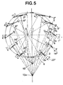
- the wheel is driven by a moving flt having a speed V. If the wheel is not subjected to any load, the wheel is driven at a peripheral speed U 0 , which in correlation with the speed V gives a resulting speed ⁇ V 0 of the wheel with respect to the moving fluid.
- the wing-shaped members 2 are oriented so that their main plane 2a is oriented patallally to the vector W 0 and the normal to the wings crossing in a single intersection 13.
- the wheel If the wheel is now subjected to a load, its speed of rotation decreases and the peripheral speed corresponds only to a value L'c.
- the fluid then moves relative to the moving wing at a resulting speed represented by the vector W c which makes with the prircipal plane 2a of the wings an angle of incidence variable according to the angular position occupied by the wing.
- the normals at these real resulting speeds W c intersect at a point 13a which, by definition, is the instantaneous rotatian center.
- the load is such that the real peripheral speed U c under load is reduced by 27% compared to the peripheral speed without load and the vectors W c therefore make with the planes main wings 2a an angle of incidence varying from 0 to 20 ° approximately.
- the angle of incidence of the wings can be controlled by an automatic adjustment device acting on the adjustment ring 16 which in turn allows to move all the guide parts 10 on the rods 9 with reference to Figure 1 and 2.
- This device can be achieved by various means, mechanical or electronic.
- An example of a mechanical embodiment is shown in FIG. 2, by a centrifugal regulator 32.
- the latter comprises an arm 28, fixed by one of its ends to the annular part 6 and another arm 29 mounted by one of its ends on the ring adjustment 16.
- a counterweight 30 subjected to the centrifugal force acts against the action of the spring 31 and in this way makes it possible to correct variations in the speed of rotation by adjusting the angle of incidence of the wings.
- the variant of the wing control device shown in FIG. 3 comprises an annular part 17 provided with as many arms 18 at its periphery as the wheel has wings.
- the adjustment of the orientation of the wings is also produced by guide pieces or pins 10 cooperating with rigid slides connected to the pivot axes of the wings, but the displacement of the pins in a substantially tangential direction is carried out by a device comprising a rod. sliding 19, ur.e link 20 and an adjusting ring 21.
- Each of the pins 10 is fixed substantially to one end of the rod 19, the other end of the latter carrying a finger 22 capable of sliding in the radial direction in a slide 23, provided on the annular part 17.
- the rod 19 is further connected to the annular part by the link 20 pivotally mounted by one of its ends on one of the arms 18 of the annular part 17 and by the other end on the rod 19.
- This rod is intended to guide the movement of the rod so that, when the latter moves, said stud 10 moves in a sensibleme direction nt tangential to a circle of diameter substantially equal to the trajectory circle of the axes of the wings.
- the adjusting ring 21 can be controlled by a centrifugal regulator 32 similar to that described with reference to FIG. 2.
- FIG. 4 Another variant of the wing control device, illustrated in FIG. 4, differs from the fact that the slides 11 and the corresponding wings 2 form an angle of 90 ° between them.
- the plane passing through the axes of rotation la and 8 of the vertical shaft, respectively of the annular part 6, must no longer be oriented parallel to the direction of movement of the fluid, as in the embodiment according to Figure 1, but perpendicular to this direction.
- the position of the intersection line 13 on the plane 14 is adjusted by moving all the guide parts or pins 10, cooperating with the slides 11, in a radial direction relative to the center, in an identical manner. of rotation 8 of the annular part 6.
- Such an adjustment can be achieved by means of a ring 28, on which rods 29 are pivotally mounted by one of their ends, the other end of these rods being fixed to the pins 10.
- the latter pass through the annular part by radial slots 30 to cooperate with the slides 11 oriented perpendicularly to the wings 2.
- the ring 28 can, as before, be controlled by a centrifugal regulator, not shown in FIG. 4.
Landscapes
- Engineering & Computer Science (AREA)
- Life Sciences & Earth Sciences (AREA)
- Sustainable Development (AREA)
- Sustainable Energy (AREA)
- Chemical & Material Sciences (AREA)
- Combustion & Propulsion (AREA)
- Mechanical Engineering (AREA)
- General Engineering & Computer Science (AREA)
- Structures Of Non-Positive Displacement Pumps (AREA)
- Prostheses (AREA)
Applications Claiming Priority (2)
| Application Number | Priority Date | Filing Date | Title |
|---|---|---|---|
| CH406181A CH643633A5 (fr) | 1981-06-19 | 1981-06-19 | Roue a pales cooperant avec un fluide. |
| CH4061/81 | 1981-06-19 |
Publications (3)
| Publication Number | Publication Date |
|---|---|
| EP0068559A2 true EP0068559A2 (de) | 1983-01-05 |
| EP0068559A3 EP0068559A3 (en) | 1984-08-15 |
| EP0068559B1 EP0068559B1 (de) | 1986-11-12 |
Family
ID=4269075
Family Applications (1)
| Application Number | Title | Priority Date | Filing Date |
|---|---|---|---|
| EP82200737A Expired EP0068559B1 (de) | 1981-06-19 | 1982-06-16 | Fluidiumbetriebenes Rad |
Country Status (5)
| Country | Link |
|---|---|
| US (1) | US4507049A (de) |
| EP (1) | EP0068559B1 (de) |
| CA (1) | CA1183756A (de) |
| CH (1) | CH643633A5 (de) |
| DE (1) | DE3274279D1 (de) |
Cited By (5)
| Publication number | Priority date | Publication date | Assignee | Title |
|---|---|---|---|---|
| WO1984001406A1 (en) * | 1982-10-06 | 1984-04-12 | Jonsson Pumpkonsult | Turbo machine of the rotodynamic type |
| GB2244099A (en) * | 1990-05-16 | 1991-11-20 | Printer Marketing Company Limi | Turbine assembly |
| WO1995008708A1 (de) * | 1993-09-21 | 1995-03-30 | Franz Schweighofer | Einrichtung zur umwandlung von wasser- oder windenergie |
| GB2360551A (en) * | 2000-03-21 | 2001-09-26 | Alan John Rogan | Turbine |
| ITUB20159512A1 (it) * | 2015-12-01 | 2017-06-01 | Chiariatti Antonio Francesco | Anello per il controllo del pitch delle pale di turbine ad asse verticale |
Families Citing this family (23)
| Publication number | Priority date | Publication date | Assignee | Title |
|---|---|---|---|---|
| US4618312A (en) * | 1985-01-28 | 1986-10-21 | Williams Robert A | Wind operated apparatus |
| AT401409B (de) * | 1995-03-08 | 1996-09-25 | Lukas Peter | Vorrichtung zur erzeugung mechanischer energie aus strömungen |
| US5855470A (en) * | 1997-03-21 | 1999-01-05 | Holmes; Alan G. | Wind wheel with rotationally faced plates |
| RU2161731C1 (ru) * | 1999-10-26 | 2001-01-10 | Ушаков Григорий Германович | Активная турбина |
| US6543999B1 (en) | 2002-02-15 | 2003-04-08 | James Van Polen | Windmill |
| EP1457672A1 (de) * | 2003-03-12 | 2004-09-15 | Arthur Bachot | Windturbine mit senkrechter Drehachse |
| NL1024958C2 (nl) * | 2003-12-05 | 2005-06-07 | Jekele Hendrik Ir Raukema | Windmolen. |
| US20070104578A1 (en) * | 2005-11-09 | 2007-05-10 | Andrews James W | Radially-sliding wind turbine |
| DE102006002137A1 (de) * | 2006-01-17 | 2007-07-19 | Schiel, Katja | Rotationssegel II |
| US20070169482A1 (en) * | 2006-01-24 | 2007-07-26 | Weightman Gerald N | Aspects derived from a discovery of the inherent properties and traits of planar curves herein classified as Limaconic Motation technology |
| CN100406719C (zh) * | 2006-02-15 | 2008-07-30 | 严强 | 垂直轴风力发电机叶片攻角调节方法和调节装置 |
| US20080236159A1 (en) * | 2007-03-27 | 2008-10-02 | Glenn Martin Tierney | Cycloidal power generator |
| US20080298965A1 (en) * | 2007-06-04 | 2008-12-04 | Michael Alan Keena | Wind Drum |
| US20090136346A1 (en) * | 2007-11-23 | 2009-05-28 | Samuel Thomas Kelly | Vertical axis wind turbine |
| US8373297B2 (en) * | 2009-01-16 | 2013-02-12 | Charles Grigg | Wind turbine generator and motor |
| EP2556244B1 (de) | 2010-01-14 | 2014-05-21 | Daniel P. Coffey | Gerät zum umsetzen von windenergie |
| US9346535B1 (en) * | 2012-04-05 | 2016-05-24 | The United States Of America As Represented By The Secretary Of The Air Force | Ring cam and ring cam assembly for dynamically controlling pitch of cycloidal rotor blades |
| CA2798526A1 (en) | 2012-11-29 | 2014-05-29 | Wayne Olaf Martinson | Fluid apparatus with pitch adjustable vanes |
| KR101483461B1 (ko) * | 2012-12-26 | 2015-01-21 | 민영희 | 회전블레이드 각도조절식 수직축 풍력발전기 |
| KR101480312B1 (ko) * | 2013-07-15 | 2015-01-08 | 주식회사 씨윈피에스 | 풍향에 따라 날개각도가 가변되는 풍력발전기의 원통형풍차 |
| US20180030956A1 (en) * | 2015-02-05 | 2018-02-01 | Vijay Rao | Fluid Turbine with Control System |
| CA3017702C (en) * | 2016-03-30 | 2023-10-10 | Adv Tech | Fluidic rotor having orientable blades with improved blade control |
| US10994840B1 (en) | 2017-08-16 | 2021-05-04 | United States Of America As Represented By The Secretary Of The Air Force | Thrust vectoring control of a cyclorotor |
Family Cites Families (26)
| Publication number | Priority date | Publication date | Assignee | Title |
|---|---|---|---|---|
| US1432700A (en) * | 1922-10-17 | Propeller | ||
| US441461A (en) * | 1890-11-25 | Apparatus with feathering blades for obtaining | ||
| DE304433C (de) * | ||||
| GB182774A (en) * | 1921-07-05 | 1923-11-30 | William Benjamin Chenoweth | Improvements in or relating to wind motors |
| US1465593A (en) * | 1921-09-30 | 1923-08-21 | Barrett John Fitzallan | Feathering mechanism for paddle-type stream motors and propellers |
| US1775593A (en) * | 1924-08-02 | 1930-09-09 | Kahn Louis Lazare | Turbine-wheel propeller or motor |
| FR640890A (fr) * | 1927-02-25 | 1928-07-24 | Moteur sustentateur et propulseur dans un fiuide | |
| AT114323B (de) * | 1928-02-02 | 1929-09-25 | Voith J M Fa | Antriebsvorrichtung für Schaufelräder. |
| US1885640A (en) * | 1929-11-20 | 1932-11-01 | Strandgren Carl Bruno | Turbine wheel propeller and motor |
| US1921534A (en) * | 1932-02-29 | 1933-08-08 | Bynum B Mccrosky | Propeller |
| DE635962C (de) * | 1932-03-11 | 1936-09-29 | Carl Bruno Strandgren | Fluegelrad, insbesondere an Flugzeugen |
| US2063549A (en) * | 1935-01-17 | 1936-12-08 | Elbert D Hale | Wind wheel |
| AT153685B (de) * | 1937-03-13 | 1938-06-25 | Ernst Schneider | Schaufelradpropeller. |
| US2291062A (en) * | 1939-02-06 | 1942-07-28 | Voith Schneider Propeller Comp | Blade wheel propeller, particularly for watercraft |
| DE742788C (de) * | 1939-06-04 | 1943-12-16 | Licht Und Kraft Ag | Vertikalachsiges Schaufelrad |
| DE860466C (de) * | 1942-06-09 | 1952-12-22 | Voith Gmbh J M | Fluegelradpropeller mit relativ zum Radkoerper isochron rotierenden Fluegeln |
| US2580428A (en) * | 1945-07-10 | 1952-01-01 | Herbert M Heuver | Cycloidal rotor for aircraft |
| FR1014530A (fr) * | 1947-07-29 | 1952-08-18 | Aéromoteur à pales animées d'un double mouvement circulaire et d'axe de rotation perpendiculaire à la direction du vent | |
| US2688285A (en) * | 1952-03-13 | 1954-09-07 | Stockett | Variable stroke control windmill |
| FR1396515A (fr) * | 1964-03-12 | 1965-04-23 | Moteur à axe vertical et à ailes orientables entraîné par un écoulement filuide | |
| GB2017230B (en) * | 1978-03-28 | 1982-07-07 | Hayes M R | Transverse flow turbines |
| DE2826180C2 (de) * | 1978-06-15 | 1981-09-24 | Friedrich 6141 Seidenbuch Roth | Windkraftmaschine mit vertikaler Hauptachse |
| NL7811248A (nl) * | 1978-11-14 | 1980-05-19 | Schelde Nv | Stromingsmachine. |
| DE2927956C2 (de) * | 1979-07-11 | 1981-10-29 | J.M. Voith Gmbh, 7920 Heidenheim | Wind- oder Wasserkraftvorrichtung |
| US4260328A (en) * | 1980-03-10 | 1981-04-07 | Hamel Roland R | Windmill |
| US4383801A (en) * | 1981-03-02 | 1983-05-17 | Pryor Dale H | Wind turbine with adjustable air foils |
-
1981
- 1981-06-19 CH CH406181A patent/CH643633A5/fr not_active IP Right Cessation
-
1982
- 1982-06-10 CA CA000404875A patent/CA1183756A/fr not_active Expired
- 1982-06-16 EP EP82200737A patent/EP0068559B1/de not_active Expired
- 1982-06-16 DE DE8282200737T patent/DE3274279D1/de not_active Expired
- 1982-06-18 US US06/390,029 patent/US4507049A/en not_active Expired - Fee Related
Cited By (8)
| Publication number | Priority date | Publication date | Assignee | Title |
|---|---|---|---|---|
| WO1984001406A1 (en) * | 1982-10-06 | 1984-04-12 | Jonsson Pumpkonsult | Turbo machine of the rotodynamic type |
| GB2158523A (en) * | 1982-10-06 | 1985-11-13 | Jonsson Pumpkonsult | Turbo machine of the rotodynamic type |
| GB2244099A (en) * | 1990-05-16 | 1991-11-20 | Printer Marketing Company Limi | Turbine assembly |
| GB2244099B (en) * | 1990-05-16 | 1995-01-11 | Printer Marketing Company Limi | Turbine assembly |
| WO1995008708A1 (de) * | 1993-09-21 | 1995-03-30 | Franz Schweighofer | Einrichtung zur umwandlung von wasser- oder windenergie |
| GB2360551A (en) * | 2000-03-21 | 2001-09-26 | Alan John Rogan | Turbine |
| GB2360551B (en) * | 2000-03-21 | 2003-01-22 | Alan John Rogan | Turbines |
| ITUB20159512A1 (it) * | 2015-12-01 | 2017-06-01 | Chiariatti Antonio Francesco | Anello per il controllo del pitch delle pale di turbine ad asse verticale |
Also Published As
| Publication number | Publication date |
|---|---|
| CH643633A5 (fr) | 1984-06-15 |
| EP0068559A3 (en) | 1984-08-15 |
| DE3274279D1 (en) | 1987-01-02 |
| CA1183756A (fr) | 1985-03-12 |
| EP0068559B1 (de) | 1986-11-12 |
| US4507049A (en) | 1985-03-26 |
Similar Documents
| Publication | Publication Date | Title |
|---|---|---|
| EP0068559B1 (de) | Fluidiumbetriebenes Rad | |
| EP1724472B1 (de) | Kontrollanlage für verstellbare Leitschaufelstufen einer Turbomaschine | |
| FR2545624A1 (fr) | Dispositif d'actionnement electromecanique compact | |
| FR2579170A1 (fr) | Organe de centrage d'un plateau oscillant, a bielles tangentielles, pour la commande du pas des pales d'un rotor d'helicoptere | |
| FR2864613A1 (fr) | Dispositif de deploiement et d'entrainement de gouvernes d'un projectile | |
| FR2534829A1 (fr) | Broyeur en cone | |
| FR3046440B1 (fr) | Module de soufflante a aubes a calage variable pour une turbomachine | |
| FR2713330A1 (fr) | Dispositif de commande de vol. | |
| EP3956219B1 (de) | Antriebsvorrichtung für einen drehflügler mit senkrechtstart und -landung und ein drehflügler mit mindestens einer solchen antriebsvorrichtung | |
| EP1772698B1 (de) | Antreibvorrichtung für die Ruder eines Geschosses | |
| EP2314507A1 (de) | Taumelscheibeneinheit für Längs- und Quersteuerung eines Hauptrotors sowie ein Hauptrotor mit einer solchen Einheit | |
| FR3126019A1 (fr) | Module de soufflante a pales a calage variable | |
| FR3020342A1 (fr) | Ensemble de plateaux cycliques pour commander le pas de pales d'un rotor, rotor et aeronef muni d'un tel ensemble | |
| EP0143061B1 (de) | Automatische Verstellvorrichtung für den Propellerblattwinkel | |
| FR3046433A1 (fr) | Module de soufflante a aubes a calage variable pour une turbomachine | |
| FR2607107A1 (fr) | Rotor d'helicoptere | |
| EP2864594B1 (de) | Bläser mit variabler einstellung der schaufeln mittels differentieller rotation der rotorscheiben des bläsers | |
| CH622065A5 (en) | Variable-geometry wind turbine | |
| CH718509A1 (fr) | Régulateur centrifuge à frottement pour mouvement horloger. | |
| FR2577516A1 (fr) | Rotor d'helicoptere | |
| EP0047694A2 (de) | Fliehkraftregler mit direktem Antrieb für einen an einem Raumfahrtkörper angelenkten Mechanismus | |
| FR2852918A1 (fr) | Dispositif de commande de vol pour giravions. | |
| FR2876752A1 (fr) | Dispositif de pas variable pour eolienne a axe de rotation dans la direction du vent agissant par action combinee de la poussee du vent sur les pales et de regulateurs centrifuges | |
| FR2610859A1 (fr) | Robot a plusieurs bras, equipes de mecanismes de coordination des mouvements de ces bras | |
| EP0383369B1 (de) | Anordnung bestehend aus einer Drehklappe und einem Antriebsorgan, verbunden durch ein Hebelgestänge |
Legal Events
| Date | Code | Title | Description |
|---|---|---|---|
| PUAI | Public reference made under article 153(3) epc to a published international application that has entered the european phase |
Free format text: ORIGINAL CODE: 0009012 |
|
| AK | Designated contracting states |
Designated state(s): DE FR GB NL SE |
|
| PUAL | Search report despatched |
Free format text: ORIGINAL CODE: 0009013 |
|
| AK | Designated contracting states |
Designated state(s): DE FR GB NL SE |
|
| 17P | Request for examination filed |
Effective date: 19850206 |
|
| GRAA | (expected) grant |
Free format text: ORIGINAL CODE: 0009210 |
|
| AK | Designated contracting states |
Kind code of ref document: B1 Designated state(s): DE FR GB NL SE |
|
| PG25 | Lapsed in a contracting state [announced via postgrant information from national office to epo] |
Ref country code: NL Effective date: 19861112 |
|
| PG25 | Lapsed in a contracting state [announced via postgrant information from national office to epo] |
Ref country code: SE Effective date: 19861130 |
|
| REF | Corresponds to: |
Ref document number: 3274279 Country of ref document: DE Date of ref document: 19870102 |
|
| NLV1 | Nl: lapsed or annulled due to failure to fulfill the requirements of art. 29p and 29m of the patents act | ||
| PLBE | No opposition filed within time limit |
Free format text: ORIGINAL CODE: 0009261 |
|
| STAA | Information on the status of an ep patent application or granted ep patent |
Free format text: STATUS: NO OPPOSITION FILED WITHIN TIME LIMIT |
|
| 26N | No opposition filed | ||
| PG25 | Lapsed in a contracting state [announced via postgrant information from national office to epo] |
Ref country code: GB Effective date: 19880616 |
|
| GBPC | Gb: european patent ceased through non-payment of renewal fee | ||
| PG25 | Lapsed in a contracting state [announced via postgrant information from national office to epo] |
Ref country code: FR Free format text: LAPSE BECAUSE OF NON-PAYMENT OF DUE FEES Effective date: 19890228 |
|
| PG25 | Lapsed in a contracting state [announced via postgrant information from national office to epo] |
Ref country code: DE Effective date: 19890301 |
|
| REG | Reference to a national code |
Ref country code: FR Ref legal event code: ST |