EP0068666A1 - Système d'entraînement pour une bande sans fin et convoyeur avec ce système d'entraînement - Google Patents
Système d'entraînement pour une bande sans fin et convoyeur avec ce système d'entraînement Download PDFInfo
- Publication number
- EP0068666A1 EP0068666A1 EP82302915A EP82302915A EP0068666A1 EP 0068666 A1 EP0068666 A1 EP 0068666A1 EP 82302915 A EP82302915 A EP 82302915A EP 82302915 A EP82302915 A EP 82302915A EP 0068666 A1 EP0068666 A1 EP 0068666A1
- Authority
- EP
- European Patent Office
- Prior art keywords
- belt
- rollers
- drive
- path
- plane
- Prior art date
- Legal status (The legal status is an assumption and is not a legal conclusion. Google has not performed a legal analysis and makes no representation as to the accuracy of the status listed.)
- Granted
Links
- 235000013305 food Nutrition 0.000 claims abstract description 6
- 238000011282 treatment Methods 0.000 claims description 5
- 239000002184 metal Substances 0.000 claims description 3
- 230000002093 peripheral effect Effects 0.000 claims 1
- 238000010276 construction Methods 0.000 description 5
- 238000007710 freezing Methods 0.000 description 5
- 230000008014 freezing Effects 0.000 description 5
- 239000011248 coating agent Substances 0.000 description 4
- 238000000576 coating method Methods 0.000 description 3
- 230000000694 effects Effects 0.000 description 3
- 238000010438 heat treatment Methods 0.000 description 2
- 229920001903 high density polyethylene Polymers 0.000 description 2
- 239000004700 high-density polyethylene Substances 0.000 description 2
- 239000010935 stainless steel Substances 0.000 description 2
- 229910001220 stainless steel Inorganic materials 0.000 description 2
- 239000004677 Nylon Substances 0.000 description 1
- 235000019219 chocolate Nutrition 0.000 description 1
- 238000010411 cooking Methods 0.000 description 1
- 239000002826 coolant Substances 0.000 description 1
- 238000001816 cooling Methods 0.000 description 1
- 239000000463 material Substances 0.000 description 1
- 229920001778 nylon Polymers 0.000 description 1
- 239000004033 plastic Substances 0.000 description 1
- 229920003023 plastic Polymers 0.000 description 1
- -1 polytetra- fluorethylene Polymers 0.000 description 1
- 230000000630 rising effect Effects 0.000 description 1
- 238000013020 steam cleaning Methods 0.000 description 1
- 238000004659 sterilization and disinfection Methods 0.000 description 1
- 239000013589 supplement Substances 0.000 description 1
Images

Classifications
-
- B—PERFORMING OPERATIONS; TRANSPORTING
- B65—CONVEYING; PACKING; STORING; HANDLING THIN OR FILAMENTARY MATERIAL
- B65G—TRANSPORT OR STORAGE DEVICES, e.g. CONVEYORS FOR LOADING OR TIPPING, SHOP CONVEYOR SYSTEMS OR PNEUMATIC TUBE CONVEYORS
- B65G21/00—Supporting or protective framework or housings for endless load-carriers or traction elements of belt or chain conveyors
- B65G21/16—Supporting or protective framework or housings for endless load-carriers or traction elements of belt or chain conveyors for conveyors having endless load-carriers movable in curved paths
- B65G21/18—Supporting or protective framework or housings for endless load-carriers or traction elements of belt or chain conveyors for conveyors having endless load-carriers movable in curved paths in three-dimensionally curved paths
-
- B—PERFORMING OPERATIONS; TRANSPORTING
- B65—CONVEYING; PACKING; STORING; HANDLING THIN OR FILAMENTARY MATERIAL
- B65G—TRANSPORT OR STORAGE DEVICES, e.g. CONVEYORS FOR LOADING OR TIPPING, SHOP CONVEYOR SYSTEMS OR PNEUMATIC TUBE CONVEYORS
- B65G23/00—Driving gear for endless conveyors; Belt- or chain-tensioning arrangements
- B65G23/02—Belt- or chain-engaging elements
- B65G23/04—Drums, rollers, or wheels
-
- B—PERFORMING OPERATIONS; TRANSPORTING
- B65—CONVEYING; PACKING; STORING; HANDLING THIN OR FILAMENTARY MATERIAL
- B65G—TRANSPORT OR STORAGE DEVICES, e.g. CONVEYORS FOR LOADING OR TIPPING, SHOP CONVEYOR SYSTEMS OR PNEUMATIC TUBE CONVEYORS
- B65G2207/00—Indexing codes relating to constructional details, configuration and additional features of a handling device, e.g. Conveyors
- B65G2207/24—Helical or spiral conveying path
Definitions
- the present invention relates to a drive system for an endless belt and a conveyor system incorporating that drive system, notably to a conveyor system for use in a food processing operation.
- the items of food are usually placed on a moving belt which is moved through a freezing station.
- the belt can be a linear belt, it has been proposed to cause the belt to follow a helical path through the freezing station around a central rotating drum.
- the frictional contact between the drum and the edge of the belt carries the belt around the drum in a similar way to that in which a rope is carried by a capstan drum.
- Typical of such a system is that described in British Patent No 1090630.
- the drive drum occupies a comparatively large volume of the whole freezing station and it is necessary to support the belt as it is carried vertically up, or down.
- Such support must be provided from the outer periphery of the belt by cantilever arm supports which are often of comparatively massive construction and which reduce the usable headroom above the surface of the belt. It has therefore been proposed, for example in BP 1420576, to form the belt with lateral walls so that the walls on one tier of the belt rest on and are supported by the walls of the tier below.
- the belt thus forms a self-supporting coil carried by a basal drive and support member.
- a construction is costly and can cause problems with adequate circulation of air over the items carried by the belt.
- US Patent No. 3682295 to drive the belt by means of an intermediate belt carrying radial lugs on which the main belt rests.
- the intermediate belt is driven by means of a series of wheels engaging the inner surface of the intermediate belt and arranged around the arc of the curve which the intermediate belt follows.
- a series of wheels engaging the inner surface of the intermediate belt and arranged around the arc of the curve which the intermediate belt follows.
- the drive system for the intermediate belt occupies the area within the spiral path of the main belt.
- the supports for the intermediate belt require considerable headroom between each successive level of the main belt.
- Such a system has in practice not proved feasible for multi-tier use and its commercial use has been restricted to the driving of the feed or off-take sections of a main belt being driven by a drum as in BP 1090630.
- the single drive drum used hitherto at each 180 or 360° curve in the path of the belt is replaced by a plurality of smaller drive rollers engaging directly with the edge of the belt.
- These rollers-drive and support the belt and achieve a low tension drive system but enable the belt to be supported from both sides without the use of space consuming cantilever or other supports; and also enable the volume hitherto occupied by the single drive drum or the intermediate belt drive system to be used to locate the heating or cooling mechanism, thus leading to a more compact system.
- the drive system of the invention can be used to propel conventional belts along substantially straight paths, in which case the drive systems can be located at intervals along the run of the belt and thus reduce the overall tension in the belt.
- the drive system finds especial use where the belt follows a path which is curved in the plane of the belt, e.g. the belt travels around a helical or dog-leg path. In this case, at least one and preferably each curve in the path is provided with a drive system of the invention.
- the present invention provides a drive system for an endless belt adapted to carry articles through a path which system comprises one or more drive stations adapted to propel the belt characterised in that at least one of the drive stations comprises a plurality of rollers adapted to rotate about their longitudinal axes and to engage the belt directly and to propel the belt, the rollers having their axes of rotation generally, e.g. within +20 0 of, normal to the plane of the belt at the point of contact when the belt is in position, with the proviso that where the belt is to travel around a path having one or more curves in the plane of the belt, at least one of those curves is provided with a drive station as defined above.
- the present invention also provides a conveyor system which comprises an endless belt adapted to carry articles through a path, the belt being adapted to be propelled parallel to its plane characterised in that the belt is provided with one or more drive stations, at least one of which comprises a plurality of rollers rotatable about their longitudinal axes, which rollers engage directly with and are adapted to propel an edge of the belt, the axes of rotation of the rollers being generally, i.e. within +20 0 of, normal to the plane of the belt at the points of contact.
- the belt is one which can be longitudinally collapsed across its width so that the belt can be curved in its plane and the path which the belt follows is preferably one containing at least one curve.
- the path which the belt follows is preferably one containing at least one curve.
- the present invention further provides a conveyor system which comprises an endless belt which is adapted to carry loads and is progressively longitudinally collapsible across its width, whereby it can conform to a path having curves in the plane of the belt, which belt is formed into a circuit having one or more curves in the plane of the belt characterised in that at least one curve of the belt is provided with a drive station comprising a plurality of rotatable drive rollers which engage directly with and are adapted to propel an edge of the belt, the axis of rotation of the rollers being within +20 0 of, normal to the plane of the belt at the points of contact.
- the drive rollers are located at the inner radius of each curve in the path through which the belt travels and act also to support that edge of the belt with which they engage.
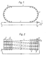
- a collapsible belt 1 is caused to travel around a generally helical path.
- the path need not be of oval plan as shown in Figure 1, but could be circular or of a more complex and convoluted form. However, it is preferred to have a simple path in which the belt is carried through several complete turns of 360°, e.g. 3 to 40 turns, around the vertical axis of a substantially symmetrical plan-view path.
- the belt 1 is of any suitable form, e.g. a chain link, slatted or corrugated rubber belt, which can collapse longitudinally along its inner edge to follow a curved path.
- the belt is made from stainless steel or plastic-coated metal and many suitable forms are commercially available.
- a particularly suitable form comprises a series of rods or bars linking two collapsible chains which form the outer edges of the belt.
- the bars can carry a mesh or expanded metal platform to provide a plane surface to the belt.
- Such a belt can be collapsed along one edge to adopt an arcuate form as shown in Figure 4, the radii of curvature of the edges of the belt having a common centre.
- suitable belts for present use are those sold by Ashworth Brothers Inc of the United States of America.
- the central drive drum used hitherto is replaced by a series of smaller drive rollers 2 disposed around the inner radius of the path around which the belt is carried.
- the rollers 2 are mounted at 5 to 20° intervals along each curve to provide a smooth carriage of the belt around each curve of the path. However, larger intervals between rollers may be acceptable.
- the rollers are arranged so that the belt travels around each curve with its outer edge 3 fully extended and its inner edge 4 fully collapsed.
- rollers serve to support the belt radially as it travels around the arc of the curve and also to drive the belt.
- Each roller can be driven, e.g. by suitable chain drive, belting or gearing from a prime mover (not shown). However, if desired some (e.g. every other one) of the rollers can be undriven and merely act as idling supports.
- the rollers can take the form of simple cylindrical rollers or can be provided with longitudinal ribs or flutes which support the belt and act as drive ribs. If desired the roller or its ribs or flutes can be given an anti-slip coating where excessive slip between the roller and the belt might otherwise occur.
- a stainless steel roller can have high density polyethylene ribs affixed thereto, or be fitted with a rubber sleeve.
- the belt follow a generally helical path, for example with the belt rising (or falling) as it travels through each curve and remaining level between the curves, or vice versa.
- the longitudinal axes about which each roller rotates can be inclined, e.g. at from 5 to 10°,,to the vertical. Where the axes are inclined toward the centre of the arc of the curve, the belt will ascend as it travels around the curve, and when outward the belt will descend.
- the rollers can be formed as frusto cones and rotate about substantially vertical axes to achieve a similar effect.
- roller is that shown in Figure 3 and comprises a substantially cylindrical roller mounted with its longitudinal axis of rotation substantially vertical.
- the surface of the roller is provided with circumferential grooves 5 or ribs 6 to form circumferential recesses adapted to receive the inner edge 4 of the belt.
- the recesses can be provided with an annular rubber or similar sleeve to'improve the frictional contact between the roller and the edge of the belt.
- the recess serves the function of providing the drive surface of the roller and also acts to support the inner edge of the belt.
- the recesses on successive rollers on that curve can be formed higher up the roller; or rollers of essentially identical construc.tion can be mounted at progressively increasing heights around the arc of the curve. If desired, support members can also be provided between rollers to provide additional support to the belt. Also, the surface of the recess which supports the belt can be shaped so as to maximise the area of contact between the roller and the belt.
- the outer edge of the belt also requires to be supported. This can be achieved by providing support fingers or rails 7 under each tier of the belt or by providing the belt with upstanding lateral walls as in BP 1420576 to form a self-supporting stack. Alternatively, a series of rollers similar to those used at the inner radius of the curve can be used. If desired, these outer rollers can be driven to supplement the driving effect of the inner rollers, or can merely be idler rollers. As shown in Figure 1, there may be straight sections of belt between the curves where the drive rollers are located. It is preferred to support both edges of the belt over these straight portions, which can be inclined as shown in Figure 2, or can be level. Suitable support means include lateral support fingers or rails or further rollers.
- the support means can provide lateral restraint, for example as when a vertical upstand 8 is provided to the support means 7 as shown in Figure 3.
- the bearing surfaces of the support means can be given a low friction surface coating or layer, e.g. of high density polyethylene or polytetra- fluorethylene.
- Suitable take-off means include a separate belt drive station 10 in which the belt is drawn off the generally helical path, e.g. by an opposed pair of vertical drive rollers of the type used in the generally helical path, or a conventional horizontal drive roller which can carry teeth to engage in the lateral slats of the belt.
- the belt is then returned by a suitable path to the feed in to the generally helical path to form a closed loop of belt.
- the belt in this return portion can be subjected to steam cleaning or other treatments;further,the strip can be twisted in this return portion so that the closed loop of belt adopts a Mobius configuration to reduce lateral wear on the belt by alternating the edges carried on the drive rollers.
- the drive rollers 2 and the take-off means 10 are actuated and cause the belt 1 to come under tension and bear in slipping frictional contact directly against the drive rollers 2.
- the belt is moved through the generally helical path at the desired rate under the influence of the drive rollers.
- the take-off means operates at a speed of belt travel the same as or slower, e.g. 5 to 50% slower, than the linear rate of travel of the belt along the generally helical path.
- Articles, e.g. pieces of foodstuff are fed to the feed-in point (A) of the belt; are carried through the generally helical path; and are removed at the off-take point B having undergone the desired treatment.
- the rate of travel of the belt can be varied over wide ranges to suit the items carried on the belt and the treatment to be carried out.
- the drive system as a series of individual drive rollers in direct contact with the belt, the central space within the helical path is no longer obstructed and can be utilised to aid optimum flow of, e.g. coolant or heating, medium over items carried on the belt.
- the conveyor system of the invention finds widespread use wherever it is desired to carry items on a path.
- the system finds use in carrying items through a warehouse or store, in which case the path will not be the generally helical path described above, but could be a series of straight runs connected by 45°, 90°, 180° or other angled bends to form a tortuous path serving the various bays of the warehouse or store.
- the invention is of especial use where it is desired to cause a treating medium (e.g. steam or air) or a coating agent (e.g. chocolate) to flow over items carried on the belt which follows a helical or other path within an enclosed treatment zone.
- a treating medium e.g. steam or air
- a coating agent e.g. chocolate
Landscapes
- Engineering & Computer Science (AREA)
- Mechanical Engineering (AREA)
- Structure Of Belt Conveyors (AREA)
- Freezing, Cooling And Drying Of Foods (AREA)
Applications Claiming Priority (2)
| Application Number | Priority Date | Filing Date | Title |
|---|---|---|---|
| GB8119881 | 1981-06-27 | ||
| GB8119881 | 1981-06-27 |
Publications (2)
| Publication Number | Publication Date |
|---|---|
| EP0068666A1 true EP0068666A1 (fr) | 1983-01-05 |
| EP0068666B1 EP0068666B1 (fr) | 1988-06-08 |
Family
ID=10522854
Family Applications (1)
| Application Number | Title | Priority Date | Filing Date |
|---|---|---|---|
| EP82302915A Expired EP0068666B1 (fr) | 1981-06-27 | 1982-06-07 | Système d'entraînement pour une bande sans fin et convoyeur avec ce système d'entraînement |
Country Status (5)
| Country | Link |
|---|---|
| EP (1) | EP0068666B1 (fr) |
| JP (1) | JPS5811403A (fr) |
| AU (1) | AU8494182A (fr) |
| DE (1) | DE3278634D1 (fr) |
| ZA (1) | ZA824377B (fr) |
Cited By (5)
| Publication number | Priority date | Publication date | Assignee | Title |
|---|---|---|---|---|
| ES2127080A1 (es) * | 1995-10-16 | 1999-04-01 | Castano Juan Antonio Segura | Maquina para cocinar alimentos de forma continua. |
| ES2127079A1 (es) * | 1995-10-16 | 1999-04-01 | Castano Juan Antonio Segura | Instalacion para cocinar alimentos de forma continua. |
| EP1086033A4 (fr) * | 1998-02-18 | 2008-01-16 | Span Tech Llc | Systeme de convoyeur, a flexion laterale pourvu d'un dispositif de reduction des forces de trainee |
| EP2154089A3 (fr) * | 2008-08-14 | 2011-06-22 | Krones AG | Transporteur sans fin à trajet courbe |
| CN102502181A (zh) * | 2011-10-22 | 2012-06-20 | 芜湖市贺记食品有限公司 | 传送带的传动装置 |
Citations (3)
| Publication number | Priority date | Publication date | Assignee | Title |
|---|---|---|---|---|
| FR1385156A (fr) * | 1964-03-11 | 1965-01-08 | Fordertechnik Gmbh | Installation de transport à bande transporteuse à maillons |
| US3682295A (en) * | 1970-05-11 | 1972-08-08 | Ashworth Bros Inc | Edge driven conveyor system |
| DE2106708A1 (de) * | 1971-02-12 | 1972-08-17 | Neff Maschbau Heinrich | Vorrichtung zum Auf- oder Abwärtsfördern von Gläsern, Flaschen, Dosen und dergleichen |
-
1982
- 1982-06-07 EP EP82302915A patent/EP0068666B1/fr not_active Expired
- 1982-06-07 DE DE8282302915T patent/DE3278634D1/de not_active Expired
- 1982-06-17 AU AU84941/82A patent/AU8494182A/en not_active Abandoned
- 1982-06-21 ZA ZA824377A patent/ZA824377B/xx unknown
- 1982-06-25 JP JP57108605A patent/JPS5811403A/ja active Pending
Patent Citations (3)
| Publication number | Priority date | Publication date | Assignee | Title |
|---|---|---|---|---|
| FR1385156A (fr) * | 1964-03-11 | 1965-01-08 | Fordertechnik Gmbh | Installation de transport à bande transporteuse à maillons |
| US3682295A (en) * | 1970-05-11 | 1972-08-08 | Ashworth Bros Inc | Edge driven conveyor system |
| DE2106708A1 (de) * | 1971-02-12 | 1972-08-17 | Neff Maschbau Heinrich | Vorrichtung zum Auf- oder Abwärtsfördern von Gläsern, Flaschen, Dosen und dergleichen |
Cited By (7)
| Publication number | Priority date | Publication date | Assignee | Title |
|---|---|---|---|---|
| ES2127080A1 (es) * | 1995-10-16 | 1999-04-01 | Castano Juan Antonio Segura | Maquina para cocinar alimentos de forma continua. |
| ES2127079A1 (es) * | 1995-10-16 | 1999-04-01 | Castano Juan Antonio Segura | Instalacion para cocinar alimentos de forma continua. |
| EP1086033A4 (fr) * | 1998-02-18 | 2008-01-16 | Span Tech Llc | Systeme de convoyeur, a flexion laterale pourvu d'un dispositif de reduction des forces de trainee |
| EP2154089A3 (fr) * | 2008-08-14 | 2011-06-22 | Krones AG | Transporteur sans fin à trajet courbe |
| US8011496B2 (en) | 2008-08-14 | 2011-09-06 | Krones Ag | Conveyor means for articles |
| EP2626321A1 (fr) * | 2008-08-14 | 2013-08-14 | Krones AG | Convoyeur sans fin avec un trajet courbé |
| CN102502181A (zh) * | 2011-10-22 | 2012-06-20 | 芜湖市贺记食品有限公司 | 传送带的传动装置 |
Also Published As
| Publication number | Publication date |
|---|---|
| AU8494182A (en) | 1983-01-06 |
| JPS5811403A (ja) | 1983-01-22 |
| EP0068666B1 (fr) | 1988-06-08 |
| DE3278634D1 (en) | 1988-07-14 |
| ZA824377B (en) | 1983-05-25 |
Similar Documents
| Publication | Publication Date | Title |
|---|---|---|
| EP0650575B1 (fr) | Convoyeur pour congelateur | |
| US4944162A (en) | Helical conveyor food freezer | |
| US3664487A (en) | Endless helical conveyer and belt | |
| EP0333565B1 (fr) | Chambre de climatisation avec convoyeur | |
| US4901844A (en) | Low tension plastic conveyor belt system | |
| US4276980A (en) | Conveyor belt for conveyor system | |
| JP3155974B2 (ja) | コンベア装置 | |
| US5501319A (en) | Conveyor belt with asymmetric edge links | |
| US5884753A (en) | Conveyor system | |
| US4448301A (en) | Conveyor system with frictionally driven conveyor belt | |
| US6125995A (en) | External guide assembly for reducing conveyor belt drag | |
| EP0068666B1 (fr) | Système d'entraînement pour une bande sans fin et convoyeur avec ce système d'entraînement | |
| GB2067494A (en) | Endless conveyors | |
| US3603450A (en) | Enclosed belt conveyor | |
| US5038923A (en) | Mini-roller conveyor with variable pressure traction sleeve | |
| US4893708A (en) | Conveyor for freezing food packages | |
| NL8700099A (nl) | Transportinrichting met aangedreven kogels, beschermbaar tegen overbelasting. | |
| GB2063201A (en) | Conveyor apparatus | |
| EP1572560B1 (fr) | Installation de support et son element porteur | |
| EP4416085B1 (fr) | Transporteur en spirale et entraînement à tambour pour un transporteur en spirale | |
| US1948090A (en) | Conveyer | |
| EP2212222A1 (fr) | Convoyeur hélicoïdal | |
| US3807246A (en) | Work table drive | |
| US3840111A (en) | Chain conveyor | |
| US2211801A (en) | Can handling machine |
Legal Events
| Date | Code | Title | Description |
|---|---|---|---|
| PUAI | Public reference made under article 153(3) epc to a published international application that has entered the european phase |
Free format text: ORIGINAL CODE: 0009012 |
|
| 17P | Request for examination filed |
Effective date: 19820608 |
|
| AK | Designated contracting states |
Designated state(s): BE CH DE FR GB IT LI NL SE |
|
| ITF | It: translation for a ep patent filed | ||
| RAP1 | Party data changed (applicant data changed or rights of an application transferred) |
Owner name: APV HALL LIMITED |
|
| RAP1 | Party data changed (applicant data changed or rights of an application transferred) |
Owner name: APV BAKER LIMITED |
|
| GRAA | (expected) grant |
Free format text: ORIGINAL CODE: 0009210 |
|
| AK | Designated contracting states |
Kind code of ref document: B1 Designated state(s): BE CH DE FR GB IT LI NL SE |
|
| PG25 | Lapsed in a contracting state [announced via postgrant information from national office to epo] |
Ref country code: LI Effective date: 19880608 Ref country code: CH Effective date: 19880608 Ref country code: BE Effective date: 19880608 |
|
| REF | Corresponds to: |
Ref document number: 3278634 Country of ref document: DE Date of ref document: 19880714 |
|
| ET | Fr: translation filed | ||
| REG | Reference to a national code |
Ref country code: CH Ref legal event code: PL |
|
| PLBE | No opposition filed within time limit |
Free format text: ORIGINAL CODE: 0009261 |
|
| STAA | Information on the status of an ep patent application or granted ep patent |
Free format text: STATUS: NO OPPOSITION FILED WITHIN TIME LIMIT |
|
| 26N | No opposition filed | ||
| ITTA | It: last paid annual fee | ||
| EAL | Se: european patent in force in sweden |
Ref document number: 82302915.2 |
|
| PGFP | Annual fee paid to national office [announced via postgrant information from national office to epo] |
Ref country code: SE Payment date: 19960528 Year of fee payment: 15 |
|
| PGFP | Annual fee paid to national office [announced via postgrant information from national office to epo] |
Ref country code: GB Payment date: 19960529 Year of fee payment: 15 |
|
| PGFP | Annual fee paid to national office [announced via postgrant information from national office to epo] |
Ref country code: FR Payment date: 19960611 Year of fee payment: 15 |
|
| PGFP | Annual fee paid to national office [announced via postgrant information from national office to epo] |
Ref country code: DE Payment date: 19960612 Year of fee payment: 15 |
|
| PGFP | Annual fee paid to national office [announced via postgrant information from national office to epo] |
Ref country code: NL Payment date: 19960626 Year of fee payment: 15 |
|
| REG | Reference to a national code |
Ref country code: GB Ref legal event code: 732E |
|
| NLT1 | Nl: modifications of names registered in virtue of documents presented to the patent office pursuant to art. 16 a, paragraph 1 |
Owner name: APV UK PLC;APV CORPORATION LIMITED |
|
| NLS | Nl: assignments of ep-patents |
Owner name: AAF-MCQUAY INCORPORATED;PORTALEGRE LIMITED |
|
| REG | Reference to a national code |
Ref country code: GB Ref legal event code: 732E |
|
| REG | Reference to a national code |
Ref country code: FR Ref legal event code: TP Ref country code: FR Ref legal event code: CD |
|
| REG | Reference to a national code |
Ref country code: FR Ref legal event code: RM |
|
| PG25 | Lapsed in a contracting state [announced via postgrant information from national office to epo] |
Ref country code: GB Free format text: LAPSE BECAUSE OF NON-PAYMENT OF DUE FEES Effective date: 19970607 |
|
| PG25 | Lapsed in a contracting state [announced via postgrant information from national office to epo] |
Ref country code: SE Effective date: 19970608 |
|
| PG25 | Lapsed in a contracting state [announced via postgrant information from national office to epo] |
Ref country code: NL Effective date: 19980101 |
|
| GBPC | Gb: european patent ceased through non-payment of renewal fee |
Effective date: 19970607 |
|
| PG25 | Lapsed in a contracting state [announced via postgrant information from national office to epo] |
Ref country code: FR Free format text: LAPSE BECAUSE OF NON-PAYMENT OF DUE FEES Effective date: 19980227 |
|
| EUG | Se: european patent has lapsed |
Ref document number: 82302915.2 |
|
| NLV4 | Nl: lapsed or anulled due to non-payment of the annual fee |
Effective date: 19980101 |
|
| PG25 | Lapsed in a contracting state [announced via postgrant information from national office to epo] |
Ref country code: DE Free format text: LAPSE BECAUSE OF NON-PAYMENT OF DUE FEES Effective date: 19980303 |
|
| REG | Reference to a national code |
Ref country code: FR Ref legal event code: ST |
|
| REG | Reference to a national code |
Ref country code: FR Ref legal event code: ST |