EP0068667A1 - Dispositif de réglage de vitesse pour machine à coudre - Google Patents
Dispositif de réglage de vitesse pour machine à coudre Download PDFInfo
- Publication number
- EP0068667A1 EP0068667A1 EP82302923A EP82302923A EP0068667A1 EP 0068667 A1 EP0068667 A1 EP 0068667A1 EP 82302923 A EP82302923 A EP 82302923A EP 82302923 A EP82302923 A EP 82302923A EP 0068667 A1 EP0068667 A1 EP 0068667A1
- Authority
- EP
- European Patent Office
- Prior art keywords
- speed setting
- lever
- shaft
- setting device
- members
- Prior art date
- Legal status (The legal status is an assumption and is not a legal conclusion. Google has not performed a legal analysis and makes no representation as to the accuracy of the status listed.)
- Granted
Links
Images


Classifications
-
- D—TEXTILES; PAPER
- D05—SEWING; EMBROIDERING; TUFTING
- D05B—SEWING
- D05B69/00—Driving-gear; Control devices
- D05B69/14—Devices for changing speed or for reversing direction of rotation
- D05B69/18—Devices for changing speed or for reversing direction of rotation electric, e.g. foot pedals
Definitions
- the present invention relates generally to industrial sewing machines, and in particular to a speed setting device for such sewing machines.
- Industrial sewing machines include a motor and a control box fixed to the underside of the motor.
- An operator-controlled lever is pivotally mounted on one side wall of the control box, one end of the pivoted lever being connected by a Pitman rod to the foot pedal of the sewing machine.
- the angular displacement of the foot pedal is transmitted via the lever to inside of the control box where a swingable arm is located.
- the free end of the arm is formed into the shape of an arch adjacent to which is located an angular displacement sensor for generating a speed setting signal in response to the rotation of the arm.
- the speed setting signal is used to control the speed of the motor to effect various automatic functions including variable speed control, needle position detection and stoppage and thread cutting operation.
- One disadvantage of the conventional speed setting device is that the lever and the arm must be rigidly coupled together with such a strength that there is no slippage at the point of coupling. If this strength is not sufficient, the slippage will result in an error in the speed setting signal.
- Another disadvantage relates to the fact that the maximum range of angular displacement is not sufficient for the displacement sensor to generate a position signal which is an accurate representation of the angular position of the foot pedal. As a result, an extra device is needed for amplifying the amount of angular displacement of the arm. '
- the present invention provides an improved speed setting device for industrial sewing machines which is free from the problems associated with conventional speed setting devices.
- the speed setting device of the invention comprises a first member, or lever pivoted at one end thereof to a stationary wall and adapted to be pivotally moved in response to the operator's action.
- a second member, or arm is pivoted at one end to the stationary wall and operatively engaged with the first member so that they rotate in unison about their respective pivot points.
- the pivot point of the second member is located intermediate the pivot point of the first member and the point of engagement between the first and second members.
- the angular displacement detector preferably comprises a permanent magnet mounted on the pivot point of the second member and a magnetic flux sensor stationarily mounted with respect to the magnet for detecting the direction of magnetic flux of the magnet.
- the pivot points of the first and second members are formed by a shaft comprising oil-impregnated material or polyacetal to assure smooth rotary movement of the arms.
- the speed setting device for generating a speed setting signal of a sewing machine by detecting the angular displacement of a foot pedal in response to an operator's action.
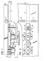
- the speed setting device comprises a lever 5 having an iron pivot shaft 11 firmly inserted to one end of thereof.
- a linkage shaft 12 extends parallel with the pivot shaft 11 from a point intermediate the ends of the lever 5.
- the lever 5 is formed by aluminum diecast or molded resin injection technique.
- the pivot shaft 11 extends through an opening 20 of a wall 3 and rotatably mounted on a bearing 8 secured to the wall 3 opposite to the lever 5 by screws 8a.
- the wall 3 forms part of a control box of the industrial sewing machine and is formed with a part-circular opening 4 through which the linkage shaft 12 extends to operatively engage with an elongated opening 16 of a rotary arm 13.
- the arm 13 is provided with a pivot shaft 21 at one end thereof which is rotatably mounted on a bearing 9 secured to the wall 3 by screws 9a.
- the arm 13 and its pivot shaft 21 are preferably formed of the same material as the pivot shaft 11.
- the bearings 8 and 9 are each formed of an oil-impregnated molded polyacetal to assure smooth movement of the levers 5 and 13 for an extended period of time.
- a permanent magnet 14 is fitted to the pivot shaft 21 of the arm 13 so that the direction of magnetic flux rotates with the rotation of the arm 13.
- a magnetic sensor such as magnetoresistive element 15 is mounted on a printed circuit assembly 17 which is secured by a bracket 18 to the wall 3, whereby the pivot movement of the arm 13 is detected by a change in voltage generated by the magnetic sensor 15.
- the lever 5 is maintained in a neutral position by means upper and lower springs 6 and 7 secured to the wall 3.
- the lever 5 is suitably linked by a Pitman rod to the foot pedal, not shown, of the sewing machine so that when the foot pedal is depressed forward from a neutral position the lever 5 is rotated counterclockwise as indicated by a solid line in Fig. 3 and when the foot pedal is depressed backward from the neutral position the lever 5 is turned clockwise as indicated by a dot-dash line.
- Fig. 4 is an illustration of the detail of the bearing 9.
- the distance between the magnet 14 and magnetic sensor 15 be maintained constant. This is accomplished by an arrangement comprising a spacer 24 which is attached to the surface of the magnetic sensor 15.
- the shaft 21 of arm 13 is formed with an opening 22 in which a compression spring 23 is disposed to urge the magnet 14 slightly against the spacer 24.
- a further arrangement for accurate indication of the depression includes a torsion spring 25 which is coiled around the bearing 9 with its one end fixed thereto as at 26 and its other end fixed to the arm 13 as at 27.
- the spring 25 biases the arm 13 against the second shaft 12 of the lever 5 to eliminate the loose play which might otherwise occur between it and the inner wall of the opening 16 so that the lever 5 and the rotary arm 13 may rotate in complete unison.
- Figs. 5 to 7 are illustrations of a practical embodiment of the invention. Illustrated at 1 in Fig. 5 is a motor which is mounted below the sewing machine table, not shown.
- the control box 3, which is resin molded or aluminum diecast, is fixed to the motor 1 by a metal fixture or bracket 2.
- the lever 5, which is also resin molded or aluminum diecast, is shown connected to the pivot shaft 11 at 5B and to the connecting shaft 12 at 5C.
- the lever 5 has at the free end thereof a hole 5A in which a Pitman rod, not shown, is rigidly inserted for coupling the lever 5 to the sewing machine foot pedal, not shown.
- the spring 6 is shown depending from a projection 3A of the control box 3 to pull the lever upward and the spring 7 is provided in a cylindrical housing 7B with a rod 7A therein, the rod 7A being disposed between the spring 7 and the lever 5 to urge the latter downward.
- the spring 7 is designed to be sufficiently stronger than the spring 6 so that the lever 5 is normally located in a neutral position as illustrated.
- the lever 5 Upon forward depression of the foot pedal by the operator, the lever 5 turns counterclockwise about its pivot point 5B against-the spring 6 to a position as illustrated, this forward depression being limited by the engagement of the connecting shaft 12 with the lower end of the arcuate slot 4 provided on a side wall of the control box.
- the lever 5 Upon backward depression of the foot pedal, the lever 5 turns clockwise against the spring 7 until the connecting shaft 12 engages the upward end of the arcuate slot 4.
- the bearing 8 shown mounted to an inner wall. of the control box 3 is formed of molded oil-impregnated oleopolyacetal to which the pivot shaft 11 rotatably supported, the axial movement of the shaft 11 being prevented by means of a washer lla and an E-shaped retaining ring llb.
- the permanent magnet 14 is shown insert-molded with the rotary arm 13.
- Fig. 7 is an illustration of the detail of the mounting of the bearing 8. As shown the bearing 8 extends through an opening provided in the side wall of the control box 3 and secured thereto by screws 8a, 8a.
Landscapes
- Engineering & Computer Science (AREA)
- Mechanical Engineering (AREA)
- Textile Engineering (AREA)
- Sewing Machines And Sewing (AREA)
Applications Claiming Priority (2)
| Application Number | Priority Date | Filing Date | Title |
|---|---|---|---|
| JP89882/81 | 1981-06-11 | ||
| JP56089882A JPS57203479A (en) | 1981-06-11 | 1981-06-11 | Apparatus for setting speed of sewing machine |
Publications (2)
| Publication Number | Publication Date |
|---|---|
| EP0068667A1 true EP0068667A1 (fr) | 1983-01-05 |
| EP0068667B1 EP0068667B1 (fr) | 1985-09-11 |
Family
ID=13983132
Family Applications (1)
| Application Number | Title | Priority Date | Filing Date |
|---|---|---|---|
| EP82302923A Expired EP0068667B1 (fr) | 1981-06-11 | 1982-06-07 | Dispositif de réglage de vitesse pour machine à coudre |
Country Status (6)
| Country | Link |
|---|---|
| US (1) | US4499449A (fr) |
| EP (1) | EP0068667B1 (fr) |
| JP (1) | JPS57203479A (fr) |
| KR (1) | KR850001707B1 (fr) |
| CA (1) | CA1198320A (fr) |
| DE (1) | DE3266162D1 (fr) |
Cited By (1)
| Publication number | Priority date | Publication date | Assignee | Title |
|---|---|---|---|---|
| DE4241446C1 (de) * | 1992-12-09 | 1993-10-07 | Pfaff Ag G M | Betätigungsvorrichtung mit eingebautem Drehzahl-Sollwertgeber für den Antriebsmotor einer Nähmaschine |
Families Citing this family (11)
| Publication number | Priority date | Publication date | Assignee | Title |
|---|---|---|---|---|
| JPS5797118A (en) * | 1980-12-09 | 1982-06-16 | Matsushita Electric Ind Co Ltd | Speed setter of sewing machine |
| JPS6239684U (fr) * | 1985-08-29 | 1987-03-09 | ||
| JPS6247379U (fr) * | 1985-09-09 | 1987-03-24 | ||
| JPS6247380U (fr) * | 1985-09-13 | 1987-03-24 | ||
| JPS6247382U (fr) * | 1985-09-13 | 1987-03-24 | ||
| DE69121386T2 (de) * | 1991-03-27 | 1996-12-19 | Comelz Spa | Steuerungseinheit für einen elektrischen Antriebsmotor einer industriellen Verarbeitungsmaschine |
| US5477116A (en) * | 1993-11-22 | 1995-12-19 | Textron Inc. | Golf car having modular accelerator pedal assembly with non-contacting position sensor |
| DE4412555C2 (de) * | 1994-04-11 | 2000-06-21 | Mannesmann Ag | Ein analoges Steuersignal abgebendes Tastelement für die Steuerung von Elektromotoren |
| US5587634A (en) * | 1994-11-29 | 1996-12-24 | Ara Electronics Corp. | Human body actuated control apparatus and system for commercial sewing machines |
| DE10117597C1 (de) * | 2001-04-07 | 2002-11-28 | Itt Mfg Enterprises Inc | Wippschalter |
| US9139943B2 (en) * | 2013-03-14 | 2015-09-22 | Columbia Insurance Company | Drive link system and tufting machines comprising same |
Citations (1)
| Publication number | Priority date | Publication date | Assignee | Title |
|---|---|---|---|---|
| EP0053938A1 (fr) * | 1980-12-09 | 1982-06-16 | Matsushita Electric Industrial Co., Ltd. | Dispositif de réglage de vitesse pour machine à coudre |
Family Cites Families (9)
| Publication number | Priority date | Publication date | Assignee | Title |
|---|---|---|---|---|
| US1772361A (en) * | 1928-03-19 | 1930-08-05 | Hamilton Beach Mfg Co | Motor controller |
| US2455691A (en) * | 1945-12-22 | 1948-12-07 | Cameron B Mcculloch | Sound transmission control system |
| US2501159A (en) * | 1947-10-07 | 1950-03-21 | Winslow B M Clark | Rheostatic control |
| US2534939A (en) * | 1949-12-05 | 1950-12-19 | Elbern H Alkire | Pedal control for rheostats |
| JPS51150447A (en) * | 1975-02-19 | 1976-12-24 | Hitachi Ltd | Device for detecting change in pedal angle of sewing machine |
| DE7539310U (de) * | 1975-12-10 | 1976-04-01 | Frankl & Kirchner, Fabrik Fuer Elektromotoren U. Elektrische Apparate, 6830 Schwetzingen | Einrichtung zur hoechststichzahlbegrenzung von naehmaschinen |
| JPS5821126Y2 (ja) * | 1976-08-06 | 1983-05-04 | 電気音響株式会社 | ポテンシヨメ−タ |
| US4125821A (en) * | 1977-08-05 | 1978-11-14 | Denki Onkyo Company, Limited | Potentiometer providing a non-linear output |
| DE2913861C2 (de) * | 1979-04-06 | 1981-07-09 | Frankl & Kirchner GmbH & Co KG Fabrik für Elektromotoren u.elektrische Apparate, 6830 Schwetzingen | Betätigungsvorrichtung für einen Steuerschalter |
-
1981
- 1981-06-11 JP JP56089882A patent/JPS57203479A/ja active Granted
-
1982
- 1982-05-27 KR KR8202354A patent/KR850001707B1/ko not_active Expired
- 1982-06-07 US US06/386,785 patent/US4499449A/en not_active Expired - Lifetime
- 1982-06-07 DE DE8282302923T patent/DE3266162D1/de not_active Expired
- 1982-06-07 EP EP82302923A patent/EP0068667B1/fr not_active Expired
- 1982-06-10 CA CA000404856A patent/CA1198320A/fr not_active Expired
Patent Citations (1)
| Publication number | Priority date | Publication date | Assignee | Title |
|---|---|---|---|---|
| EP0053938A1 (fr) * | 1980-12-09 | 1982-06-16 | Matsushita Electric Industrial Co., Ltd. | Dispositif de réglage de vitesse pour machine à coudre |
Cited By (1)
| Publication number | Priority date | Publication date | Assignee | Title |
|---|---|---|---|---|
| DE4241446C1 (de) * | 1992-12-09 | 1993-10-07 | Pfaff Ag G M | Betätigungsvorrichtung mit eingebautem Drehzahl-Sollwertgeber für den Antriebsmotor einer Nähmaschine |
Also Published As
| Publication number | Publication date |
|---|---|
| KR850001707B1 (ko) | 1985-11-26 |
| KR830010241A (ko) | 1983-12-26 |
| JPS6124955B2 (fr) | 1986-06-13 |
| JPS57203479A (en) | 1982-12-13 |
| US4499449A (en) | 1985-02-12 |
| DE3266162D1 (en) | 1985-10-17 |
| CA1198320A (fr) | 1985-12-24 |
| EP0068667B1 (fr) | 1985-09-11 |
Similar Documents
| Publication | Publication Date | Title |
|---|---|---|
| EP0068667B1 (fr) | Dispositif de réglage de vitesse pour machine à coudre | |
| US20120187940A1 (en) | Device for detecting the position of a shift and/or selector lever for a transmission and shift device for the transmission of a motor vehicle | |
| US6530293B1 (en) | Shift mechanism for motor vehicle transmissions | |
| US6408712B1 (en) | Pedal assembly with non-contact pedal position sensor for generating a control signal | |
| EP0053938B1 (fr) | Dispositif de réglage de vitesse pour machine à coudre | |
| US6089120A (en) | Vehicle operating pedal unit | |
| US5812050A (en) | Electrical control apparatus with unidirectional tactile indicator | |
| JP2000118259A (ja) | アクセルペダルモジュ―ル | |
| JP3129609B2 (ja) | ペダルの踏込みストローク検出装置 | |
| WO2003021207A1 (fr) | Dispositif de detection du niveau d'un liquide | |
| US5969495A (en) | Accelerator device for electromotive vehicles | |
| EP1376049B1 (fr) | Capteur utilisant un transducteur magnétique pour mesurer l'angle de rotation d'un arbre comprenant une came | |
| JP3898913B2 (ja) | 液面レベルセンサ | |
| US6925958B2 (en) | Driving device including a position indicator | |
| US2674447A (en) | Speedometer | |
| US20090100959A1 (en) | Apparatus for actuating a motor vehicle pedal position sensor | |
| JP2011093411A (ja) | シフト装置 | |
| JPH0577555B2 (fr) | ||
| US5959421A (en) | Motor direction control device for electromotive vehicles | |
| US2979704A (en) | Overload detector | |
| EP1825226A1 (fr) | Potentiometre optique et ensemble a levier de commande | |
| JP2638939B2 (ja) | ミシンの布送り制御装置 | |
| JPS6219343Y2 (fr) | ||
| JPH0687040U (ja) | 車両のペダル位置検出装置 | |
| JPH0727415Y2 (ja) | センサ一体型ユニット |
Legal Events
| Date | Code | Title | Description |
|---|---|---|---|
| PUAI | Public reference made under article 153(3) epc to a published international application that has entered the european phase |
Free format text: ORIGINAL CODE: 0009012 |
|
| AK | Designated contracting states |
Designated state(s): DE FR GB |
|
| 17P | Request for examination filed |
Effective date: 19830222 |
|
| GRAA | (expected) grant |
Free format text: ORIGINAL CODE: 0009210 |
|
| AK | Designated contracting states |
Designated state(s): DE FR GB |
|
| REF | Corresponds to: |
Ref document number: 3266162 Country of ref document: DE Date of ref document: 19851017 |
|
| ET | Fr: translation filed | ||
| PLBE | No opposition filed within time limit |
Free format text: ORIGINAL CODE: 0009261 |
|
| STAA | Information on the status of an ep patent application or granted ep patent |
Free format text: STATUS: NO OPPOSITION FILED WITHIN TIME LIMIT |
|
| 26N | No opposition filed | ||
| PGFP | Annual fee paid to national office [announced via postgrant information from national office to epo] |
Ref country code: FR Payment date: 19940609 Year of fee payment: 13 |
|
| PG25 | Lapsed in a contracting state [announced via postgrant information from national office to epo] |
Ref country code: FR Effective date: 19960229 |
|
| REG | Reference to a national code |
Ref country code: FR Ref legal event code: ST |
|
| REG | Reference to a national code |
Ref country code: GB Ref legal event code: 746 Effective date: 19960628 |
|
| PGFP | Annual fee paid to national office [announced via postgrant information from national office to epo] |
Ref country code: DE Payment date: 20000605 Year of fee payment: 19 |
|
| PGFP | Annual fee paid to national office [announced via postgrant information from national office to epo] |
Ref country code: GB Payment date: 20000607 Year of fee payment: 19 |
|
| PG25 | Lapsed in a contracting state [announced via postgrant information from national office to epo] |
Ref country code: GB Free format text: LAPSE BECAUSE OF NON-PAYMENT OF DUE FEES Effective date: 20010607 |
|
| PG25 | Lapsed in a contracting state [announced via postgrant information from national office to epo] |
Ref country code: DE Free format text: LAPSE BECAUSE OF NON-PAYMENT OF DUE FEES Effective date: 20010630 |
|
| GBPC | Gb: european patent ceased through non-payment of renewal fee |
Effective date: 20010607 |