EP0068672B1 - Spreiz- und Zuführvorrichtung - Google Patents
Spreiz- und Zuführvorrichtung Download PDFInfo
- Publication number
- EP0068672B1 EP0068672B1 EP82302959A EP82302959A EP0068672B1 EP 0068672 B1 EP0068672 B1 EP 0068672B1 EP 82302959 A EP82302959 A EP 82302959A EP 82302959 A EP82302959 A EP 82302959A EP 0068672 B1 EP0068672 B1 EP 0068672B1
- Authority
- EP
- European Patent Office
- Prior art keywords
- conveyor
- clamps
- gate
- clamp
- belts
- Prior art date
- Legal status (The legal status is an assumption and is not a legal conclusion. Google has not performed a legal analysis and makes no representation as to the accuracy of the status listed.)
- Expired
Links
- 230000004044 response Effects 0.000 claims description 16
- 230000007480 spreading Effects 0.000 claims description 16
- 230000009471 action Effects 0.000 claims description 5
- 238000007599 discharging Methods 0.000 claims description 4
- 230000001419 dependent effect Effects 0.000 claims 1
- 230000000977 initiatory effect Effects 0.000 claims 1
- 230000002441 reversible effect Effects 0.000 description 10
- 238000003908 quality control method Methods 0.000 description 9
- 238000010586 diagram Methods 0.000 description 8
- 238000005096 rolling process Methods 0.000 description 4
- 238000012546 transfer Methods 0.000 description 4
- 238000012545 processing Methods 0.000 description 3
- 239000007921 spray Substances 0.000 description 3
- 230000001960 triggered effect Effects 0.000 description 3
- 230000001154 acute effect Effects 0.000 description 2
- 230000000295 complement effect Effects 0.000 description 2
- 238000010276 construction Methods 0.000 description 2
- 230000007547 defect Effects 0.000 description 2
- 230000002950 deficient Effects 0.000 description 2
- 238000013461 design Methods 0.000 description 2
- 230000000694 effects Effects 0.000 description 2
- 241000743339 Agrostis Species 0.000 description 1
- 238000013459 approach Methods 0.000 description 1
- 238000007664 blowing Methods 0.000 description 1
- 230000008859 change Effects 0.000 description 1
- 230000008878 coupling Effects 0.000 description 1
- 238000010168 coupling process Methods 0.000 description 1
- 238000005859 coupling reaction Methods 0.000 description 1
- 230000003111 delayed effect Effects 0.000 description 1
- 238000000151 deposition Methods 0.000 description 1
- 238000006073 displacement reaction Methods 0.000 description 1
- 238000003780 insertion Methods 0.000 description 1
- 230000037431 insertion Effects 0.000 description 1
- 230000007246 mechanism Effects 0.000 description 1
- 239000002184 metal Substances 0.000 description 1
- 230000009467 reduction Effects 0.000 description 1
- 230000000630 rising effect Effects 0.000 description 1
- 125000006850 spacer group Chemical group 0.000 description 1
Images








Classifications
-
- D—TEXTILES; PAPER
- D06—TREATMENT OF TEXTILES OR THE LIKE; LAUNDERING; FLEXIBLE MATERIALS NOT OTHERWISE PROVIDED FOR
- D06F—LAUNDERING, DRYING, IRONING, PRESSING OR FOLDING TEXTILE ARTICLES
- D06F67/00—Details of ironing machines provided for in groups D06F61/00, D06F63/00, or D06F65/00
- D06F67/04—Arrangements for feeding or spreading the linen
Definitions
- This invention relates to spreader feeder apparatus for spreading laundry flatwork pieces before feeding them to subsequent processing equipment.
- U.S. Patent No. 4,050,173 discloses a spreader feeder apparatus having paired spreader belts 35, 36 at the entry side of the apparatus and paired clamps 8, 9,10 and 11 above for moving a laundry piece from one side to the centre of the entry and then spreading it laterally before releasing it.
- a blade 32 transfers the released laundry piece onto the conveyor 1 below.
- U.S. Patent No. 3,729,846 discloses a spreader feeder apparatus with four loading stations A, B, C and D, each having a pair of transfer clips TC for holding the top corners of the laundry piece. At a central feeding station E the laundry piece is transferred to clamps 6, which move apart until the leading edge of the laundry piece is straightened. The clamps 6 release the laundry piece and the horizontal air tubes 10 blow it onto the conveyor 1. Spreader belts 7 and 8 spread the trailing part of the laundry piece.
- U.S. Patent No. 3,664,046 discloses a spreader feeder apparatus with three loading stations 20, 22 and 24 each having a pair of clips 26 for holding the top corners of a laundry piece. At a central unloading position clamps 30 remove the laundry piece from the clips 26, and then these clamps move apart to straighten the top edge of the laundry piece, after which it is dropped onto a conveyor 38. Paired belts 46 below spread the trailing part of the laundry piece.
- U.S. Patent No. 3,376,036 discloses a spreader feeder apparatus with two feed positions, each having a pair of grips 6 for holding the top corners of a laundry piece. At a central transfer station the top corners of the laundry piece are transferred to clamps 4, which are then spread apart until the leading edge of the laundry piece is straightened, as detected by a photocell 15. Then the leading end of the laundry piece is dropped onto a conveyor 1.
- a further object of the invention is to incorporate safety switches with the spreading belts of a spreader feeder apparatus for disabling the belts when a foreign object such as hand is caught between the belts.
- the apparatus is for spreading laundry flatwork pieces, such as bed sheets, before feeding them to subsequent processing equipment, such as an ironer and a folder.
- the flatwork pieces are spread apart by pairs of clamps, there normally being one pair of clamps at the left end, another pair of clamps at the right end, and a third pair of clamps at the centre of the apparatus.
- the spread-out flatwork pieces may be blown onto a conveyor for conveying them to the subsequent processing apparatus.
- Trailing edge sensors may be positioned at different levels below the clamps to sense the upward passage of the bottom edge of the laundry flat piece deposited on the conveyor, and a selector switch enables one of the sensors and disables the other, depending upon the speed at which the conveyor is being operated.
- Proximity switches may sense the positions of the clamps.
- an overlying conveyor co-operating with the main conveyor for sandwiching the laundry flat piece as it is moved into the apparatus for stretching purposes.
- the main conveyor can be moved to an extended position beyond the clamps to facilitate hand feeding of small laundry flat pieces without engagement by the clamps.
- Spreader belts may be used spread the laundry flat piece laterally, and the spreader belts may have outwardly projecting bristles for engaging the laundry flat piece very effectively.
- a safety switch may be associated with each pair of spreader belts to detect the presence between them of a foreign object, and the spreader belts stopped in response to the actuation of either safety switch.
- Air discharge pipes are preferably provided with nozzles for discharging vertically narrow, horizontally thin-shaped laterally diverging streams of air which merge with each other to form a continuous blanket of air flowing above the conveyor.
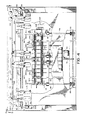
- the present apparatus has a framework with laterally spaced, wheel- mounted, upstanding, sheet metal end cabinets 30 and 31 and a horizontally elongated top carriage 32 extending between the end cabinets at the top and slidably adjustable between the normal operating position, shown in full lines in Figure 8, and a retracted position shown in phantom in Figure 8, for a purpose explained hereinafter.
- a wide, flexible endless belt conveyor 33 is located below the top carriage 32 and extends for almost the complete lateral distance between the upstanding end cabinets 30 and 31.
- This conveyor has a plurality of laterally spaced, relatively narrow, flexible endless bents 33a with upper runs or courses of travel which extend into the apparatus (which for convenience of description will be referred to as the forward direction).
- the conveyor belts 33a extend up across a lower front roller 330 and up across and over an upper front roller 331, passing forward (i.e. into the machine) from roller 331 to an intermediate upper idler roller 332, and forward from the latter to a rear roller 333, passing down across the back of the latter and then back toward the entry side of the machine to an intermediate idler roller 334, and down across the latter to a lowermost roller 335, passing up across the front of the lowermost roller 335 to another intermediate roller 336, and passing up across the top of roller 336 to the roller 330.
- the rollers 331, 332, 333, 334 and 336 have stationary axes of rotation.
- the lower front roller 330 is displaceable from the normal position shown in Figure 2, where it is almost directly beneath the upper front roller 331, to the extended position shown in Figure 17, where it projects outward from the machine at its entry side.
- the lowermost roller 335 is displaceable from the normal, lowered position shown in Figure 1 to the raised position shown in Figure 17.
- the upper front roller 331 is driven from an electric motor 337 ( Figure 4) through a gear reduction 338.
- the motor 337 is located at the right side of the machine, viewed from its entry side as shown in Figure 4.
- Rollers 332 and 353 are also driven.
- the other rollers 330, 333, 334, 335 and 336 for the conveyor belts 33a are idler rollers.
- the motor drive to the upper front roller 331 and rollers 332 and 353 is in a direction to move the conveyor belts 33a from right to left in Figure 2 across the top of the roller 331 over to the intermediate upper roller 332.
- each end the lower front roller 330 is rotatably mounted in a respective carrier 340 which is displaceable longitudinally by a respective pneumatic cylinder-and-piston unit 341.
- a rack 342 ( Figure 17) extends from each roller carrier 340 at the opposite end from where it supports the roller 330. This rack has downwardly facing teeth which mesh with a small rotatable first pinion gear 343.
- a fixed rack 344 has upwardly facing teeth which engage the pinion 343 from below.
- a similar second pinion 345 is engaged between the respective racks 342 and 344 a short distance forward (i.e., into the machine) from the first pinion 343.
- the upper and lower racks 342 and 344 at each end of roller 330 extend parallel to each other. As best seen in Figure 18, both pinions 343 and 345 of each pair are rotatably supported by a plate 346 which is connected by a cross pin assembly 346' to the outer end of the piston of the respective cylinder-and-piston unit 341.
- the cross pin assembly 346' includes a bolt 700 received in a sleeve bearing or bushing 701 carried by a yoke 702 on the outer end of the piston rod 341a ( Figure 14) of the cylinder-and-piston unit 341.
- the screw-threaded inner end of bolt 700 is attached to a cylindrical rod 703, which is movable along an inclined slot 704 in the inside wall 705 of a housing 706 for the cylinder-and-piston unit 341.
- This housing 706 is fixedly mounted on the corresponding end cabinet 30 or 31.
- the inner end of the slide rod 703 is rigidly connected to the aforementioned plate 346.
- the plate 346 is located at the inner side of the lower rack 344 and the upper rack 342.
- Plate 346 rotatably supports the pinions 343 and 345 near its opposite ends.
- Figure 23 shows the pivotal support for the pinion 343 in the form of a bolt 707 having a screw-threaded stem threadedly received in the plate 346 and a smooth cylindrical shank segment outside the plate on which the pinion 343 is rotatable.
- Bolt 707 has an enlarged head on its outer end which is received in a complementary counterbore 343a formed in the outer end face of pinion 343.
- the other pinion 345 has an identical pivotal support on plate 346.
- a pair of upper and lower guide rails 708 and 709 (Figure 23) are bolted to the inside wall 705 of housing 706.
- the lower rack 344 is affixed to the inside of the lower guide rail 709 by the same bolts which mount this guide rail on the housing wall 705.
- the guide rails 708 and 709 are located above and below the slot 704 in the housing wall 705 and they extend at the same inclination downward toward the entry side of the machine.
- the lower rack 344 is fixedly mounted on the housing 706, and it is inclined downward toward the entry side of the machine.
- the roller carrier 340 comprises top and bottom plates 710 and 711 to which an inner plate 712 is attached by bolts 713 to provide a unitary channel.
- the upper rack 342 is attached by bolts 714 to the bottom of the top plate 710.
- the top plate 710 has a flat bottom face which slidably engages the flat top face of the upper guide rail 708.
- the flat bottom face of the lower rack 344 and the flat bottom face of the lower guide rail 709 are slidably engaged by the top face of the bottom plate 711 of the roller carrier 340.
- roller carrier 340 and the upper rack 342 are slidable as a unit along the fixed guide rails 708 and 709.
- the lower front roller 330 of the conveyor is rotatably mounted on a horizontal shaft 715 by a ball bearing 716 at each end.
- the shaft 715 extends beyond the roller into a central opening 717 in the end wall 712 of the roller carrier 340.
- This end wall presents a cylindrical projection 718 at its inner end which extends concentrically around the opening 717. Inside this projection the end wall 712 presents a flat end face 719.
- a pair of cylindrical spacers 720 and 721 are engaged between this end face and the outside of the ball bearing 716 for roller 330.
- roller 330 is moved at a differential rate of 2:1 as compared to the movement of the piston.
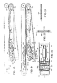
- the lower roller 335 for the conveyor belt 33a is rotatably mounted on the front ends of respective arms 348 ( Figures 2 and 3). The back ends of these arms are horizontally pivoted at 349.
- a pair of tension springs 350 and 351 act on these arms to pull them down to the horizontal position shown in Figures 2 and 3.
- the conveyor belts 33a pull the lower roller 335 up.
- the downward pull of springs 350 and 351 maintains the conveyor belts 33a under the desired degree of tension in both positions of rollers 330 and 335.
- a pivoted cover plate 470 ( Figure 14) normally is held up in front of rollers 330 and 331 by a magnetic catch 471. This plate 470 is manually moved down out of the way ( Figure 19) when the roller 330 is moved to its extended position.
- the conveyor also has sets of upper, flexible, endless conveyor belts 352 (Figure 2) which overlie the lower conveyor belts 33a where the latter pass over the roller 332.
- the upper conveyor belts 352 extend around a front idler roller 353 and a back idler roller 354, which are respectively located in front of and behind the roller 332.
- roller 332 The vertical position of roller 332 is such that it flexes the lower run of the upper conveyor belts 352 upward slightly to maintain an appropriate tension on these belts.
- the purpose of the upper conveyor belts 352 is to hold the laundry flatwork down on the lower conveyor belts 33a near roller 332, and to exert a stretching action on the flatwork.
- the back roller 335 for the lower conveyor belts 33a and the back roller 354 for the upper conveyor belts 352 are rotatably supported at their opposite ends by respective plates 355 ( Figures 2,3,17 and 18). These plates 355 are pivotally connected to the upper ends of respective posts 356 which, as shown in Figure 2, are inclined downward from these plates toward the entry side of the machine. The lower ends of the posts 356 are pivotally supported from the framework of the machine. The length of the posts 356 is telescopically adjustable to provide the desired belt tension in the conveyor.
- two pairs of confronting, laterally directed, flexible endless belts 41-42 and 43-44 are located a short distance below the conveyor belts 33a.
- the paired belts 41-42 are at the left side of the longitudinal centreline of the conveyor 33, and the paired belts 43-44 are at the right side of this centreline.
- the left-hand belts 41-42 present contiguous runs which move from the centre laterally outward to the left for spreading from the centre to the left the part of a sheet which passes up between them.
- the right-hand belts 43 ⁇ 44 present contiguous runs which move from the centre laterally outward to the right for spreading from the centre to the right another part of the same sheet passing up between them. Therefore, the paired belts 41-42 and 43-44 will be referred to as spreader belts.
- the respective rear spreader belts 42 and 44 are longer than the respective spreader belts 41 and 43 with which they are paired, and they extend laterally inward past the latter toward the longitudinal centreline of the apparatus. This provides a gap between the front belts 41 and 43 midway across the apparatus at its entry side where a sheet may hang down directly behind the rear belts 42 and 44. This facilitates the passage of the sheet up between the confronting pairs of spreader belts 41-42 and 43-44, with the belts 41-42 spreading part of the sheet to the left as it passes up between them and with the belts 43-44 spreading another part of the sheet to the right as it passes up between them.
- the rear belt 44 is driven by a vertical drive roller 45 ( Figure 2) at its laterally outboard (right) end.
- This drive roller is on the upper end of a rotatable vertical shaft 46 which extends up from a pulley 47 driven by a belt 48 from an idler pulley 49.
- the idler pulley is driven from an electric motor 50 by a belt 51.
- the shorter front belt 43 at this side of the machine is driven by a vertical drive roller 52 ( Figure 2) at its laterally outboard (right) end.
- This drive roller is on the upper end of a vertical shaft 53 which carries a gear 54 driven by a gear 55 on shaft 46.
- Shaft 43 is rotatably mounted on the framework of the machine.
- the other pair of spreader belts 41, 42 are driven in the same manner, with the confronting, contiguous runs of these belts being pulled from right to left laterally outward in Figure 1.
- the drive arrangement for belts 41, 42 is a mirror image of the one for belts 43, 44 and therefore need not be described in detail.
- the drive roller and other parts associated with belt 42 are given the same reference numerals as those associated with belt 44, but with a "prime" suffix added.
- the laterally inward end of spreader belt 44 extends around a rotatably mounted idler roller 56.
- the laterally inward end of spreader belt 42 extends around a rotatably mounted idler roller 56'. Both of these idler rollers are supported from the framework of the machine.
- a pivotally articulated three-piece linkage is located inside the endless loop formed by spreader belt 43.
- this linkage comprises a fixedly mounted member 57, which is located toward belt 44, a pivotally adjustable member 58, which is located away from belt 44, and a linkage piece 62 acting between members 57 and 58.
- the linkage members 57 and 58 are pivotally connected at 59 a short distance laterally inward from the drive roller 52 for belt 43.
- Each of the linkage members 57 and 58 is generally channel-shaped in cross-section and the pivotally adjustable member 58 fits snugly but slidably outside the fixed member 57.
- the fixed linkage member 57 carries an idler roller 60 (Figure 9), which is located in close proximity to belt 44.
- Belt 43 extends around this idler roller 60 atthe beginning of its laterally outward run or course of movement in contiguous, confronting relationship to belt 44.
- the third linkage piece 62 has upper and lower walls 62a and 62b ( Figure 10) which respectively fit closely below and above the upper and lower walls of the fixed linkage member 57.
- aligned vertical pivot pins 61 Figure 10 connect its upper and lower walls to the corresponding walls of linkage member 57.
- the linkage piece 62 carries a roller 63 around which the spreader belt 43 extends.
- the linkage member 62 has a bridge segment 62c ( Figure 9) which extends between and interconnects its upper and lower walls. This bridge segment is located just inside the spreader belt 43 where the latter passes from roller 63 to roller 60.
- Aligned arcuate slots 64 are formed in the upper and lower walls 62a and 62b of linkage piece 62, as best seen in Figure 9.
- a cross pin 65 carried by the pivotally adjustable linkage member 58 is snugly but slidably received in these slots 64 to couple the third linkage piece 62 to the pivoted linkage member 58.
- a pneumatic cylinder-and-piston unit 66 acts between the fixed linkage member 57 and the third linkage piece 62 for moving the spreader belt between its normal position, shown in full lines in Figure 9 and in phantom in Figure 11, to a retracted position, shown in full lines in Figure 11.
- the cylinder of this unit is pivotally mounted at 67 on a bracket 68 attached to the inside of linkage member 57.
- the piston of this unit has a square extension 69 on its outer end which is rigidly fastened to a channel-shaped yoke 70.
- This yoke carries a cross pin 71 whose opposite ends are received in complementary openings in the upper wall 62a and the lower wall 62b of the third linkage piece.
- a safety switch is provided to stop the belts if one of the machine operators gets her hand caught between the belts.
- Figures 9, 12 and 13 show the safety switch arrangement for belts 43-44.
- the safety switch arrangement for belts 41-42 is the same.
- a snap-acting switch 500 is mounted inside the rear spreader belt 44.
- the actuator 501 of this switch engages the back of a flat plate 502, which extends across an opening 503 formed in an elongated plate 504 extending directly behind the run of belt 44 which is next to the front spreader belt 43 of this pair.
- the laterally inward edge of the opening 503 is located inward past the front spreader belt 43 in the latter's normal operating position, as shown in Figure 9.
- the laterally outward edge of the opening 503 is located outward past the roller 60 where the spreader belts 43 and 44 first come into confronting, contiguous relationship to one another.
- a pair of spring biased pins 505 and 506 extend behind plate 502 at its opposite ends. These pins normally hold plate 502 against the back of the longer plate 504.
- Each spreader belt 41, 42, 43 and 44 presents a plurality of closely spaced, outwardly protruding bristles across its entire extent for more effectively gripping the laundry flatwork.
- blowpipes B-1, B-2 and B-3 ( Figure 1) extend horizontally above the level of the conveyor belts 33a at the entry side of the machine.
- the left and right blowpipes B-1 and B-2 extend transversely across the conveyor for most of its width respectively to the left and right of the longitudinal centreline of the machine.
- the middle blowpipe B-3 extends transversely across a narrow region at the centre of the conveyor 33.
- the left blowpipe B-1 comprises an elongated horizontal tube 360 having an air inlet connection 361 midway along its length and having its opposite ends closed.
- the tubes 360 on one side carries a plurality of discharge nozzles 362 at evenly spaced intervals along its length.
- Each nozzle has a horizontally elongated, vertically narrow discharge opening 363 ( Figure 24), so that air is discharged from the nozzle in a fan-like pattern which has a narrow dimension vertically and a much wider, diverging flow transverse to the conveyor 33.
- the fan-like discharges from adjacent nozzles 362 merge into each other to provide a continuous forwardly moving blanket of air across the entire transverse extent of the conveyor 33 served by that blowpipe.
- the right blowpipe B-2 is of the same construction as the blowpipe B-1.
- the nozzles 362 may be set into the corresponding blowpipe tube 360 at acute angles so that the central axis of each nozzle's spray pattern extends forward and laterally outward at an acute angle.
- the middle blowpipe B-3 has a short horizontal tube carrying a small number of spray nozzles which are set to spray forward and laterally outward on each side, so that the combined action of the three blowpipes B-1, B-2 and B-3 is an uninterrupted blanket of forwardly moving air which completely covers the conveyor 33 from side to side.
- This blanket of air moves at a slight angle upward with respect to the path of the conveyor belts 33a from the upper front roller 331 to the intermediate roller 332 ( Figure 2).
- This forwardly moving blanket of air holds the laundry flatwork piece down on the conveyor belts 33a until it passes beneath the upper conveyor belts 352, from which point the upper conveyor belts 352 hold it down on the lower conveyor belts until it approaches the point (at the rear roller 333) where it moves off the lower conveyor belts 33a.
- a pair of vertical straps 364 suspend the left blowpipe B-1 in the horizontal position shown in Figure 2. This is also true of the right blowpipe B-2.
- the short middle blowpipe B-3 is suspended by a vertical strap 365.
- the upper ends of these straps are attached to the top carriage 32 of the machine. Thus, the blowpipes move in unison with the top carriage 32 when it is displaced, as described hereinafter.
- Flexible hoses 366 connect the blowpipes B-1, B-2 and B-3 to a suitable source of pressurized air through normally-closed solenoid valves.
- the top carriage 32 is mounted on two rollers 392 ( Figures 4 and 8) at each side of the machine. These rollers roll along fixed horizontal tracks 393 at the top of the respective end cabinets 30 and 31 of the machine.
- a pneumatic cylinder-and-piston unit 394 ( Figure 8) moves the top carriage between a normal position (shown in full lines in Figure 8) and a retracted position (shown in phantom in Figure 8). In its normal position, the top carriage closes a limit switch 389, for a purpose explained hereinafter. In its retracted position, the top carriage closes a limit switch 389'.
- the pair of pneumatic cylinder-and-piston units 394 for positioning the top carriage 32, the pair of pneumatic cylinder-and-piston units 341 for positioning the lower front roller 330 of conveyor 33, and the pair of pneumatic cylinder-and-piston units 66 for positioning the spreader belts 41 and 43 are operated in synchronism such that:
- the top carriage 32 carries three pairs of sheet clamps, each pair served by an individual machine operator whose job is to insert the adjacent corners on the upper end of a sheet or other large laundry workpiece into his or her pair of clamps, after which these clamps are spread apart laterally from the middle of the apparatus to the left and right, respectively.
- the three pairs of clamps are operated one at a time and they act on different sheets. Normally, the three pairs of clamps are positioned at the middle, left end and right end of the apparatus.
- the middle clamps are designated M-1 and M-2 in Figure 1
- the left end clamps are designated L-1 and L-2
- the right end clamps are designated R-1 and R-2.
- the clamps do not operate when short workpieces are being fed into the machine.
- the clamps M-1 and M-2 release the respective corners of this sheet after these clamps stop at their outermost positions to the left and right, respectively.
- the blowpipes B-1, B-2 and B-3 then discharge air to force the just-released, spread- open leading end of the sheet down onto the forwardly-advancing upper run of conveyor 33.
- the timing of the release of the sheet by the clamps and the discharge of air by the blowpipes is under the control of a photoelectric sensor 78 ( Figure 2) at the longitudinal centre of the machine. As both clamps move laterally outward, the top edge of the sheet moves past sensor 78 which senses the rising middle part of the sheet's top edge. Adjustment of the height of 78 and its reflector controls the tension of the sheet.
- An adjustable time delay is provided between this sensing and the stopping of the laterally outward movement of the clamps. This allows for adjusting the tension on the sheet.
- the clamps open to release the sheet after they reach their outermost positions, provided the spacing between successive sheets is sufficient.
- the blowpipes B-1, B-2 and B-3 are supplied with pressurized air for an adjustable time interval to blow the just-released sheet onto the conveyor 33.
- This conveyor 33 pulls the trailing part of the sheet up between the paired spreader belts 41-42 and 43 ⁇ 44, and these paired belts continue to spread the sheet laterally outward in each direction as it is drawn up between them.
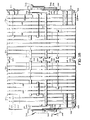
- Two trailing edge sensors 98 and 99 are located respectively below the left-hand spreader belts 41, 42 and the right-hand spreader belts 43, 44. Each of these sensors comprises a photoelectric cell which senses light reflected from an adjacent reflector 98a or 99a. The position of these elements laterally of the machine is shown in Figure 7, from which it will be apparent that a sheet being spread apart by the paired spreader belts 41, 42 and 43, 44 will hang down over the photocells 98 and 99 until the trailing edge of this sheet moves up past them.
- the photocells 98 and 99 are at different levels, with photocell 98 being lower. Both are adjustable vertically but photocell 99 will always be higher. Since they are at different levels, the trailing edge of a sheet will move up past photocell 98 before it moves up past photocell 99.
- both photocells 98 and 99 will be connected in the control circuit of the machine in such a way that the circuit will respond to the energization of the last one (the higher photocell 99) to be uncovered by the upward movement of the trailing edge of the sheet past it.
- the upper photocell 99 is disabled and the control circuit will respond only to the energization of the lower photocell 98 when the trailing edge of the sheet moves past it. This is described in more detail in the following description of the Figure 20 control circuit.
- the apparatus follows a "demand" sequence of operation. That is, the order in which the respective sets of clamps are operated depends upon the order in which the machine operators signal their readiness after inserting their respective sheets in the corresponding paired clamps.
- Each sheet clamp of each pair preferably is constructed as disclosed in detail in U.S. Patent 4,106,277.
- Each clamp is operated by a respective air cylinder 87 ( Figure 15) mounted in the top carriage 32.
- the clamp is closed when air pressure is applied to the top of the air cylinder and is released from the bottom; it is opened when pressure is supplied to the bottom of the cylinder and released from the top as explained in detail in the aforementioned patent. Therefore, it will be apparent that a sheet whose top edge is held by any pair of clamps L-1 and L-2, M-1 and M-2, or R-1 and R-2 is released by those clamps when pressurized air is supplied to the lower part of the respective air cylinders 87 for those clamps.
- Figure 4 shows the middle clamp M-1 as being slightly mounted on a pair of upper and lower, cantilevered, horizontal guide rods 100-1 and 101-1, which are mounted at the left side of the top carriage 32 and terminate just short of the centerline of the machine. These guide rods are rigidly interconnected by a vertical connecting piece extending between them.
- the middle clamp M-1 has an upper roller 82 ( Figure 15), which is in rolling engagement with the top of the upper guide rod 100-1, and a lower roller 83 in rolling engagement with the bottom of the lower guide rod 101-1.
- the other middle clamp M-2 is slidably mounted on similar upper and lower cantilevered horizontal guide rods 100-2 and 101-1, which are mounted at the right side of the top carriage 32 and terminate just short of the machine's centerline.
- clamp M-2 has an upper roller 82-2 in rolling engagement with the top of the upper guide rod 100-2 and a lower roller 83-2 in rolling engagement with the bottom of the lower guide rod 101-2.
- the mounting of the rods 100-1, 101-1 for clamp M-1 and the mountings of the rods 100-2, 101-2 for clamp M-2 have enough play in them to permit the free ends of these rods to be displaced as much as 3 inches toward the entry side of the machine and away from the conveyor 33, midway across the machine at its entry side.
- An air cylinder-and-piston unit is coupled to the adjacent free inner ends of these paired rods for effecting such displacement.
- the clamps L-1 and L-2 which normally are at the left end of the apparatus are similarly mounted on a single pair of horizontal guide rods 103 and 104 ( Figure 15) which extend completely across the entry side and are spaced forward (i.e., in the direction into the apparatus away from its entry side) from the respective paired guide rods for the middle clamps M-1 and M-2.
- These guide rods 103 and 104 are interconnected by a rigid vertical piece 105.
- the right end clamps R-1 and R-2 are slidable on the same horizontal guide rods 103 and 104 as clamps L-1 and L-2.
- the two middle clamps M-1 and M-2 are coupled separately to respective flexible endless cables to be displaced from their normal position close together midway across the apparatus at its entry side to their extended positions at the left and right ends respectively, of the apparatus.
- clamp M-2 is carried by an attachment piece 106 having a vertical leg which is fastened to this clamp next to its air cylinder 87.
- This attachment piece extends up from the clamp and has its upper end attached to a horizontal cable 111.
- the cable 111 is an endless flexible cable which extends from a pulley 112 at the left end of the apparatus to a pulley 113 at its right end.
- the connection 110 between the attachment piece 106 for the clamp M-2 and the cable 111 is made on the lower horizontal run of this cable.
- the other middle clamp M-1 has a similar connection to a similar cable 115, which extends around a pulley 116 at the left side of the machine and around a pulley 117 at the right. As shown in Figure 5, the pulleys 116, 117 and cable 115 are offset in front of the pulleys 112, 113 and cable 111 to avoid interference between them.
- the left end pulley 116 for cable 115 is mounted on the output shaft of a reversible clutch-brake unit 119 of known design, having a brake which is electrically-applied and spring-released and a clutch which is electrically- engaged and spring-released for driving an output shaft in one direction or the other.
- the clutch-brake unit has an input shaft carrying a pulley driven by a flexible endless chain 122, whose opposite end is driven by an idler pulley 123.
- the idler pulley 123 is driven by a flexible endless belt 129 whose opposite end extends around a drive pulley mounted on a horizontal drive shaft 131 extending transversely across the interior of the top carriage 32 extending transversely across the interior of the top carriage 32 of the apparatus framework and rotatably supported by bearings 132 and 133 at opposite ends.
- Drive shaft 131 is driven by an electric motor 135 through a belt and pulleys. As long as motor 135 is on, the drive shaft 131 is driven continuously. Normally the clutch-brake unit 119 for cable 111 is energized so that the brake is applied and the clutch is disengaged.
- the pulley 112 at the left end of the cable 111 for the clamp M-2 is driven through a similar clutch-brake unit 124 located directly to the right of the aforementioned clutch-brake unit 119.
- the clutch-brake unit 124 has an input shaft carrying a pulley which is driven through a flexible endless chain 127 from a pulley 128 on the shaft 131.
- the outer left end clamp L-1 is coupled to a flexible endless cable 145 ( Figure 4) which is spaced below and behind the cables 111 and 115 for the middle clamps M-1 and M-2.
- Clamp L-1 is attached to the lower horizontal run of cable 145.
- Cable 145 extends around a pulley 151 at its left end and around an idler pulley 152 at .its right end.
- the inner left end clamp L-2 is coupled to a flexible endless cable 146 (Figure 5), which is located behind and below cable 145.
- Clamp L-2 is attached to the upper horizontal run of cable 146.
- Cable 146 extends around a pulley 157 at its left end and around an idler pulley 158 at its right end.
- the drive pulley 151 for cable 145 is driven through a clutch-brake unit 153 (of the type already described) from the drive shaft 131 through a chain 154.
- the drive pulley 157 for cable 146 is driven through a clutch-brake unit 158 from the drive shaft 131 through a chain 159.
- the inner right end clamp R-1 is coupled to a flexible endless cable 166 (Figure 4).
- Clamp R-1 is attached to the upper horizontal run of cable 166.
- Cable 166 extends around a drive pulley 174 at its left end and around an idler pulley 176 at its right end.
- Pulley 174 is driven through a clutch-brake unit 180 ( Figure 5) from the drive shaft 131 through a chain 181.
- the outer right end clamp R-2 is coupled to a flexible endless cable 165 (Figure 4).
- Clamp R-2 is attached to the lower horizontal run of cable 165.
- Cable 165 extends around a drive pulley 172 at its left end and around an idler pulley 171 at its right end.
- Pulley 172 is driven through a clutch-brake unit from the drive shaft 131 through a chain 182. This clutch-brake unit is below the clutch-brake unit 158 for pulley 157 and is hidden by it in Figure 5.
- the middle clamps M-1 and M-2 are at the middle of the machine and the operator there wants to insert the corners of a flatwork piece that is to be spread
- the adjacent free ends of the rods 100-1, 101-1, 100-2 and 101-2 are displaced toward the operator about 3 inches by actuating the corresponding cylinder-and-piston unit. This moves the middle clamps away from any preceding flatwork piece already in the machine. This helps particularly when the flatwork pieces are wet and liable to tangle easily.
- the free ends of their guide rods 100-1, 101-1, 100-2 and 101-2 are retracted (away from the operator and toward the conveyor 33) before they are spread apart.
- the middle clamps may be moved simultaneously from the centered position where they are close together midway across the apparatus, over to the spread apart positions in which clamp M-1 is at the left end and clamp M-2 is at the right end of the apparatus, and then they are moved simultaneously back to the centered position.
- the cable 115 is driven clockwise in Figure 4 through its clutch-brake unit 119 and the cable 111 is driven counterclockwise through its clutch-brake unit 124.
- the direction of movement of their respective cables is reversed.
- each air cylinder for each of the clamps M-1 and M-2, L-1 and L-2, and R-1 and R-2 receives airthrough a Siamese (or double) helically-wound extensible hose mounted on a corresponding trolley wire which extends horizontally from left to right across the inside of the top carriage.
- the middle clamp M-1 has a horizontally extending fitting 450 on the back ( Figure 5) which is connected to the laterally outward end of a Siamese (or double) helically-wound flexible air hose 451 for supplying air to the air cylinder on this clamp.
- this end of the helical hose is suspended by a roller 452 from a horizontal transverse wire 453 above.
- the laterally inward end of the helical air hose 451 is attached to the fixedly supported end of rigid air tubes 454, 454a ( Figure 5) which extends horizontally laterally outward to a source of pressurized air mounted inside the top carriage 32 at its left end.
- the other middle clamp M-2 has a similar air supply arrangement which is a mirror image of the one just described for clamp M-1.
- Corresponding elements of the air supply arrangement for clamp M-2 are given the same reference numerals as those for clamp M-1, but with a "prime" suffix added.
- the left-hand clamp L-1 has a fitting 455 connected to the laterally inward end of a Siamese (or double) helically-wound, flexible, horizontally extending air hose 456.
- the laterally outward end of this hose is attached to a fixedly positioned, rigid air line 457 at the left side of the top carriage 32.
- a roller (not shown) at the laterally inward end of the helical hose 456 suspends it from a horizontal trolley wire (not shown) above.
- the other left-hand clamp L-1 has a similar slidably supported Siamese (or double) helically-wound air hose connected to it in the same manner as for clamp L-2.
- This air supply arrangement for clamp L-1 is hidden below other parts of the apparatus in Figure 5.
- the right-hand clamp R-1 is connected to the laterally inward end of a Siamese (or double) helically-wound, flexible, horizontally extending air hose 458 and 458a.
- the laterally outward end of these hoses are attached to fixedly positioned, rigid air lines 459 and 459a at the right side of the top carriage.
- a roller (not shown) suspends the inward end of the hose 458 from a horizontal trolley wire (not shown) above.
- the other right-hand clamp R-2 is connected to the laterally inward end of a Siamese (or double) helically-wound, flexible, horizontally extending air hose 458 and 458b.
- the opposite end of this hose is attached to fixedly positioned rigid airlines (which are obscured in Figure 5 by other parts of the apparatus) at the right side of the top carriage 32.
- Figure 25 illustrates schematically in simplified form the control circuit for the conveyor motor 337, the spreader belt motor 50, and the clamp positioning motor 135.
- This control circuit includes a first relay coil 370 which operates a set of contacts 370a for controlling the energization of the conveyor motor 337 and a set of contacts 370b for controlling the energization of relay coil 371.
- the energization of the spreader belt motor 50 and the clamp positioning motor 135 is controlled by relay coil 371 which operates two sets of relay contacts 371a and 371b.
- the conveyor motor 337 has a thermal overload 337a which operates a set of contacts 337b.
- the spreader belt motor 50 has a thermal overload 50a which operates a set of contacts 50b.
- the clamp positioning motor 135 has a thermal overload 135a which operates a set of contacts 135b.
- the respective thermal overload contacts 337b, 50b and 135b are closed normally (i.e., as long as the corresponding motors 337, 50 and 135 are not overloaded).
- the relay coil 370 is in series with six switches and a resistor 372 across an 18 volt D.C. power supply. These six switches include a manual emergency switch 373 at the left-hand operator station at the entry side of the machine, a manual emergency switch 374 at the middle operator station, a manual emergency switch 375 at the right-hand operator station, a manual stop switch 376, a safety switch 500' associated with the spreader belts 41, 42 at the left side of the machine, and the safety switch 500 associated with the spreader 43, 44 at the right side of the machine, as already described in detail. Normally, these six switches are all closed while the machine is in operation, and therefore relay coil 370 is energized and its two sets of contacts 370a and 370b are closed.
- the conveyor motor 337 is under the control of an SCR motor controller 380 of known design.
- This motor controller has input terminals 381 connected to one phase of a 230 volt, 3-phase power supply 382 and output terminals 383 connected to the conveyor motor.
- the motor controller includes a start circuit having a 48 volt terminal 384, which is connected through the normally-closed thermal cutout contacts 337b and the normally-open relay contacts 370a to a terminal 385 of the motor controller which leads to a holding circuit therein.
- a first set of normally-open contacts 386 of a manually operated start switch is connected between the relay contacts 370a and an input terminal 387 of the motor controller 380 which is connected to a starting coil.
- relay coil 370 will be energized and its contacts 370a will be closed, the start switch contacts 386 will be open, and the thermal cutout contacts 337b for the conveyor motor will be closed. Under these circumstances, motor 337 will be energized if start switch 386 is closed momentarily.
- relay coil 370 If relay coil 370 is de-energized by opening any one of the switches 373-376, 500' and 500 in series with it or a power failure, the relay contacts 370a will open, causing the conveyor motor 337 to be de-energized. After relay coil 370 is again energized, the start switch 386 must be closed in order to restart the conveyor motor 337. Therefore, even if the de-energization of the relay coil 370 is only momentary, the machine operator must close the start switch 386 manually in order to restart the conveyor 33.
- the start switch has a second set of normally-open contacts 386' which are connected in series with the second set of relay contacts 370b operated by relay coil 370.
- the relay contacts 370b and the start switch contacts 386' are connected between one terminal of a 230 volt power supply 388 and one side of the relay coil 371.
- the opposite side of this relay coil is connected to the opposite terminal of this power supply through the normally-closed thermal overload contacts 50b of the spreader belt motor 50 and the normally-closed thermal overload contacts 135b of the clamp positioning motor 135 and a limit switch 389.
- Switch 389 is closed when the conveyor 33 is retracted and top carriage 32 moved back into position for automatic feeding of laundry work pieces by the spreader belts 41, 42 and 43, 44 and is open when the conveyor 33 is extended and the carriage is moved forward for hand feeding of short work pieces.
- relay coil 371 When energized, relay coil 371 closes its set of normally-open contacts 371a, which are in parallel with the start switch contacts 386'.
- the relay contacts 371a provide a holding circuit for keeping relay coil 371 energized after the start switch contacts 386' reopen.
- relay contacts 371b operated by relay coil 371 are connected in series with the spreader belt motor 50 and with the clamp positioning motor 135 across the power supply 392 through switch 390 and fuses 391.
- switches 373-376, 500' and 500 are all closed and relay coil 370 is energized. Consequently, the conveyor motor 337 is energized through the now-closed relay contacts 370a.
- the relay coil 371 will be energized through the now-closed relay contacts 370b when the start switch contacts 386' are closed. Consequently, the relay contacts 371b will be closed, completing an energization circuit for the spreader belt motor 50 and the clamp positioning motor 135 and the spreader belts 41, 42, 43 and 44 will operate, as described, as will the clamps operated by motor 135.
- Figure 20 shows schematically the electrical circuit for controlling the spreading and release of the flatwork which is inserted into the left station clamps L-1 and L-2.
- the circuit for the flatwork inserted in the right station clamps R-1 and R-2 is the same.
- the circuit for the flatwork inserted in the middle clamps M-1 and M-2 is simpler and is shown in Figure 21.
- circuit elements and signals pertaining to clamps L-1 and L-2 will be referred to as being in the "left channel” and the circuit elements and signals pertaining to clamps R-1 and R-2 will be referred to as being in the "right channel”, and the circuit elements and signals pertaining to clamps M-1 and M-2 will be referred to as being in the "middle channel”.
- Start/Return flip-flop 296 When a start switch at 203 is closed Start/Return flip-flop 296 is set and if the limit switches 201 and 202 for both clamps are both closed, the AND gate 200 will set a Forward/Stop flip-flop 204 which sends an output signal via an inverter 205 to one input of an AND gate 206. Assuming that a start switch has not been closed already at either the middle channel or the right channel, the other two inputs to AND gate 206 will be high or "1 ", and the AND gate 206 will send an output signal via line 207 to one input terminal of an AND gate 208. Under the circumstances assumed, the other two inputs to gate 208 will be high.
- the AND gate 208 now produces an output signal on a feedback line 209 which is connected to one inputterminal of each of two OR gates 210 and 211.
- the outputs of these OR gates are, respectively, the second and third in puts to the AND gate 206, and the signal on line 209 will cause these OR gates to maintain these second and third inputs to the AND gate 206 high irrespective of the logic level of the other input signals to these OR gates. Therefore, the feedback signal on line 209 latches the AND gate 206 in the condition to which it was actuated initially by the left channel start signal on line 205.
- the OR gate 210 has a second input at M-A which changes level in response to a centre channel "A" signal.
- the OR gate 211 has a second input at R-A which changes level in response to a right channel "A” signal.
- the AND gate 206 has been latched, as described, neither a centre channel "A” signal nor a right channel “A” signal can now interfere with or interrupt the left channel operation which was initiated by operating a left channel start button at 203, as described.
- the left channel start signal at the output side of the AND gate 208 goes through an AND gate 212 and an inverter 213 to a line L-B.
- the AND gate 208 in the left channel control circuit has two additional input lines M-B and R-B which come from the respective control circuits for the middle and right channels and which correspond to the output line L-B in the left channel circuit of Figure 21.
- Line L-A is connected to an input of one of the two OR gates 210 and 211 in the right channel control circuit and the middle channel control circuit.
- the left channel "A" signal will not affect the previously “latched” right channel control circuit (under the conditions assumed) but it will disable the AND gate 206 in the middle channel control circuit.
- the second start signal in the left channel
- the first start switch that is operated (whether for the left channel, the right channel, or the middle channel) disables the operation of the second channel to have its start signal pass through gate 208, and the second similarly disables the third. Therefore, even if two or all three of the operators attempt to start their respective channels at about the same time, the first one started will finish most of its operation before the second begins, and the second before the third.
- the AND gate 212 has a first input connected to the output of AND gate 208 and a second input via line 219 from a "forward/reverse" flip-flop 220 which will provide a "1" on line 219 if the L-2 limit switch 201 has been operated properly. Normally this will be true, and the AND gate 212 will be enabled by the respective signals on its two inputs.
- the output signal from the inverter 213 is applied via line 221 to one input of a NOR gate 222 which has its output connected to the "L-2R" block 224.
- This block represents the control circuit for the clutch-brake unit 158 ( Figure 4) for the cable 146 which positions the inner left clamp L-2.
- the inner left clamp L-2 begins to move to the right from its normal position near the left end of the apparatus over to a position at the middle of the apparatus.
- the signal level at point 223 also depends on two other inputs to the NOR gate 222.
- One of these inputs is connected via lines 225 and 226 to a flip-flop 227, which at this time establishes a low at this input.
- the third input to the NOR gate 222 is connected via line 228 to a flip-flop 252, which establishes a low at this input until the "stretch" sensor 78 has been operated by the sheet or other piece of flatwork.
- the left outer clamp L-1 begins moving to the right at the same time as the left inner clamp L-2. This is done by actuating the clutch-brake unit 153 ( Figure 5) to drive cable 145 counterclockwise in Figure 4. This is designated schematically by the "L-1 R" block 230 at the middle left in Figure 20.
- such actuation of the "L-1 R" block 230 requires an output signal of the proper level from an AND gate 231.
- One input of this AND gate is connected via lines 232 and 233 to the output of the NOR gate 222.
- a second input of this AND gate is connected via line 242 and an inverter to a flip-flop 234, which is connected through a time delay circuit 235 to the L-1 limit switch 202, which is closed while the left outer clamp L-1 is in its normal position at the left end of the apparatus.
- Such closing of the outer limit switch 202 sets the flip-flop 234to establish a high at the corresponding input of the AND gate 231.
- the signal that causes clamp L-1 to move toward the centre of the machine also supplies one input to an AND gate 600.
- the second input to this gate is supplied when the middle limit switch 601 is actuated by the clamp L-2 reaching the centre of the machine.
- Switch 601 is a proximity limit switch that senses a vane carried on the L-2 clamp carriage.
- time delay circuit 236 When both inputs are present to AND gate 600, an output appears at 602 which is applied to a time delay circuit 236.
- the time delay provided by 236 is adjustable to provide a fine adjustment (1 or 2 inches) of where the clamps stop at the centre of the machine.
- the disabling of NOR gate 222 also removes one enabling input to the AND gate 231 ahead of the "L-1 R" drive 230.
- flip-flop 227 when the flip-flop 227 is set it applies a signal via line 240 to an OR gate 241 for resetting the flip-flop 234, which now removes the other enabling input for the AND gate 231 on line 242.
- the purpose of flip-flop 234 is to control the direction of movement of clamp L-1.
- the "L-1 R" drive 230 is disabled, de-clutching the counterclockwise drive for the cable 145 in Figure 4 which had been moving the left outer clamp L-1 to the right.
- the brake actuating signal at the output of NOR gate 400 is applied to the brake 401 in the clutch-brake unit 153 for cable 145, so that it is braked to a stop simultaneously with the drive cable 146 for the left inner clamp L-2.
- the setting of flip-flop 227 also applies a signal via lines 226 and 243, through an OR gate 244, through line 604 to AND gate 603.
- the other input to AND gate 603 is high (1) since the output of AND gate 212 is high at this time. Therefore, the output of AND gate 603 is high and is passed by line 245 to one input of a NOR gate 246.
- the output of this NOR gate is connected to the "L-1 L" block 247 ( Figure 20) which controls the energization of the clutch-brake unit 153 for the cable 145.
- this input signal to the NOR gate 246 disables it from operating the "L-1 L" block 247 at this time. Therefore, the outer left clamp L-1 now pauses at its position near the middle of the apparatus.
- the inner left clamp L-2 also is under the control of flip-flop 227 via lines 226 and 225 and NOR gate 222.
- the "L-2 R" block 224 atthe upperrightwill be disabled, and the clamp L-2 will stop, in response to the setting of flip-flop 227 and itwill remain disabled until flip-flop 227 is reset.
- the outer left clamp L-1 will stop at a location just to the left of the centerline of the machine and the inner left clamp L-2 will stop at a location just to the right of this centerline.
- the duration of the clamps "pause at the middle” is determined jointly by:
- time delay circuit 248 is connected to one input of an AND gate 649, whose output is connected to a reset terminal of flip-flop 227, AND gate 649 has a second input via line 678 from the output side of a time delay circuit 605 connected to the output of the AND gate 276.
- This adjustable time delay provided by the time delay circuit 605 has the same effect as moving up or moving down the trailing edge sensor 98 or 99 whichever is effective at this time.
- a switch 606 connected to one input of the AND gate 276 determines whether the lower trailing edge sensor 98 or the upper trailing edge sensor 99 is effective.
- switch 606 In the lower position of switch 606, it is connected to a line which is continuously at a high (logic 1) potential. In this setting of the switch, whenever the trailing edge of the laundry piece moves up past the lower photocell 98, the latter will produce a logic 1 signal to the other input of AND gate 276, causing its output to go high. This lower position of switch 606 is used for higher speed operation of the conveyor 33.
- the AND gate 276 receives its first logic 1 input signal from the lower photocell 98 when the trailing edge of the laundry piece moves up past it.
- the AND gate 276 receives its second logic 1 input signal from the upper photocell 99 when the trailing edge of the laundry piece moves up past it. When this happens, the output of the AND gate 276 goes high.
- This upper position of switch 606 is used for lower speed operation of the conveyor 33.
- the time delay circuit 248 may be set to time out after 0.1 or 0.2 second, typically, and this determines the minimum duration of the clamps' pause at the middle. For example, if there is no preceding piece of flatwork in the machine or if it is a short piece, the pause at the middle will be determined by the time delay circuit 248. Usually, however, there will be a preceding flatwork piece being pulled forward by the conveyor 33, but with its trailing edge not yet past the trailing edge sensor 98 or 99 which is effective at that time. In that case, the AND gate 649 will not be enabled until substantially immediately after the trailing edge of the preceding flatwork piece moves up past the trailing edge sensor 98 or 99 whichever is effective.
- the resetting of the flip-flop 227 after the time delay also enables the NOR gate 222 again via lines 226 and 225, so that the "L-2 R" block unit 224 is actuated again and the "L-2 Brake” block 239 is disabled. Consequently, the clockwise drive to the cable 146 for the inner left clamp L-2 in Figure 5 is re-established and this clamp again begins moving to the right (from near the middle of the apparatus toward its right end).
- a time delay circuit 251 TD also controls AND gate 251 to prevent the flip-flop 252 from being triggered by the movement of clamps L-1 and L-2 past this sensor. Beginning when the clamps start moving apart until the time delay in circuit 251 TD has been completed, the "stretch” sensor is inoperative in effect because the AND gate 251 is disabled. The triggering of flip-flop 252 causes NOR gate 222 to be disabled via line 228. This action of NOR gate 222 disables the "L-2 R" block 224 and enables the "L-2 Brake” block 239. Therefore, the movement of the inner left clamp L-2 to the right is stopped.
- this disabling signal on line 228 is applied via line 263 through the OR gate 244, line 604, AND gate 603, and NOR gate 246, disabling the latter so as to disable the "L-1 L" block 247 and enable brake block 401. Therefore, the movement of the outer left clamp L-1 to the left also is stopped.
- flip-flop 252 is connected through the "Pause Before Release" time delay circuit 408 to one input terminal of an AND gate 409.
- the other input terminal of AND gate 409 is connected to the output of a "sheet overlap" time delay circuit 277 associated with a flip-flop 420 at the output side of AND gate 276.
- Flip-flop 420 is set in response to the actuation of the effective trailing edge sensor 98 or 99, as described, and circuit 277 begins to time out.
- the AND gate 409 will be enabled when flip-flop 252 has been triggered in response to "stretch" sensor 78 and after the time delay provided by 408 has elapsed.
- the output of AND gate 409 is connected to an OR gate 410 (at the lower right in Figure 20), which is enabled in response to the enabling of AND gate 409.
- the output of OR gate 410 is connected via line 255 to flip-flop 253, so that flip-flop 253 is operated in response to the enabling of OR gate 410.
- flip-flop 253 actuates the clamps L-1 and L-2 to release the sheet. (This is done through the air cylinder 87 for each clamp, as already explained).
- the clamp-release circuitry is designated schematically by the block 256 in Figure 20.
- a time delay circuit 257 associated with the flip-flop 253 restores it after a suitable time interval so as to restore the clamps to their normal condition following their release of the sheet.
- the time interval between the operation of the stretch sensor 78 and stopping of the clamp carriages depends upon the adjustment of the time delay circuit 430.
- the adjustability of this time interval enables the tension on the sheet between the clamps at the time of its release to be adjusted. This adjustment is made whenever possible by adjusting the beam of 78 higher or lower on the reflector because addition of time delay by 430 causes narrow flatwork not to be stretched as tightly as wide pieces.
- the AND gate 409 also controls the actuation of the blowpipes B-1, B-2 and B-3 for blowing onto the conveyor 33 the flatwork piece which has just been released by the left clamps L-1 and L-2.
- the output of AND gate 409 is connected through an adjustable time delay circuit 258 to trigger a flip-flop 411 which operates the block 259 which designates schematically in Figure 20 the blowpipes B-1, B-2 and B-3 and their electropneumatic controls.
- the duration of the air blasts from these blowpipes is determined by an adjustable time delay circuit 260, which is connected between the output of flip-flop 411 and its reset input, which causes the flip-flop to reset after a time delay in time delay circuit 260, thus turning off the blowpipes.
- the output of AND gate 409 is also connected to flip-flop 611 and will trigger it, provided line 233Q (the data input to flip-flop 611) is high. Since this is true from the time that the clamps begin their movement until they start back to the station after blow down of the sheet, the flip-flop 611 will be triggered each time a sheet is fed from the left station and successfully blown down onto the conveyor.
- An electro-mechanical counter is represented by block 612 in Figure 20. This is operated each time a pulse output comes from flip-flop 611. The length of the pulse depends on the time delay provided by a time delay circuit 613 through which the output signal resets 611.
- time delay circuit 258 The output of time delay circuit 258 is connected to an adjustable "Pause After Release” time delay circuit 264 whose output is connected via line 413 to flip-flop 252 to reset the latter after circuit 264 times out.
- Resetting flip-flop 252 sets flip-flop 607 through line 608 and supplies a signal to AND gate 422.
- the other input to AND gate 422 is supplied from flip-flop 607, which resets itself after a 0.1 second time delay provided by a time delay circuit 609.
- the output of AND gate 422 will be a 0.1 second pulse whenever flip-flop 252 is reset.
- This pulse output from AND gate 422 resets flip-flop 420. This inhibits the blowpipes from operating until the trailing edge passes the trailing edge sensor 98 or 99 which is effective at this time and the "sheet overlap" time delay 277 times out.
- the OR gate 267 is enabled via line 266 to apply a signal through a "reverse" line 268 which extends to one input of an OR gate 269.
- This signal through the OR gate 269 reverses the "forward/reverse” flip-flop 220, thereby making its output on line 219 low and the output from the AND gate 212 low.
- This logic level change at the output of AND gate 212 produces the signal at line 221 for disabling the NOR gate 222.
- the reversal of the flip-flop 220 also produces an output signal on line 219 which is applied to a NOR gate 271 to actuate the "L-2 L” block 272.
- This block represents schematically the reversing clutch for cable 146 ( Figure 5) which now drives this cable counterclockwise in Figure 5 to move the left inner clamp L-2 from the right end of the apparatus toward the left.
- the signal at the output of the NOR gate 271 at this time causes the NOR gate 238 to release the L-2 brake 239 which had been applied to hold the cable 146 stationary.
- This "reverse" signal passes through the OR gate 269 and is applied via line 290 to one input of an AND gate 291.
- a second input to this AND gate is from the output of AND gate 212 through a time delay circuit 431. With both inputs to the AND gate 291 now high, this AND gate delivers a reset signal via OR gate 292 to reset the flip-flop 204. This disables the AND gate 206 which, in turn, disables the AND gate 208 in the channel priority circuitry in the left channel control circuit of Figure 20. Therefore, the signal L-B at the outlet side of the inverter 213 in the left channel control circuit goes high and no longer inhibits the operation of the next channel in order.
- the second channel to have its start button pushed would have a low on equivalent "A" line. As this second channel started its "A” signal would go high, allowing the third channel to have its start button pushed to have its signal move up to its line 207.
- next channel is the middle channel, then there is no initial movement of its clamps M-1 and M-2 to the middle of the apparatus because that is their starting position, so they immediately begin to move apart when the trailing edge photocell 98 or 99 (whichever is effective) sees the trailing edge of the previous sheet and time delay 605 has expired.
- the AND gate 276 is controlled by one of the trailing edge sensors 98 or 99, as described, and its output is connected via an inverter and line 278 to one input of the AND gate 249.
- the second input to this gate is from the inverted output of flip-flop 252. This output occurs after the "pause after release” has occurred, that is, when the flip-flop is reset.
- both inputs to gate 249 are high (1) so that the output of this gate is low.
- This signal will go high when the "trailing edge” sensor 98 or 99 whichever is effective at this time is uncovered, resulting in a signal that switches from 0 to 1 at the output of gate 249. This signal will be discussed later in connection with the "Quantity Control Circuit".
- the flip-flop 227 is part of the "pause at the middle" circuitry for the left channel which performs this control function for the clamps L-1 and L-2 after they have moved together from the left over to the middle of the apparatus.
- Figure 20 shows a second time delay circuit R 236 connected to the input of flip-flop 227 through the OR gate 237.
- R 236 is part of the right channel control circuit (which is identical to the left channel control circuit) and it has its input connected via AND gate R 600 to a line R 231a in the right channel circuit which is the counterpart of AND gate 600 and line 231a in the left channel circuit.
- the output signal from R 236 now operates the flip-flop 227 the same as it was operated by the output signal from the corresponding left channel time delay circuit 236. After the "pause at the middle" interval determined by the time delay circuit 248, the latter delivers an enabling signal to one input of an AND gate 649. A second enabling signal at the other input of this AND gate appears on line 678 in response to effective trailing edge sensor 98 or 99 being uncovered by the previous piece of flatwork being fed.
- the flip-flop 227 will be reset through the AND gate 649 in response to the movement of the left channel flatwork up past the effective trailing edge sensor.
- This operation of the flip-flop 227 produces a signal on line 226 and the branch line R 225 in the right channel control circuit which is the counterpart of line 225 in the left channel control circuit of Figure 20.
- the right channel clamps R-1 and R-2 will move out to the left and right from their pause position at the middle of the apparatus so as to spread the leading edge of the right channel flatwork.
- the foregoing description assumed that the right channel was next to operate after the left channel.
- the flip-flop 227 will not be operated by the right channel time delay circuit R 236 as just described. Instead, the signal from the effective trailing edge sensor will be applied via line 294 to the middle channel control circuit ( Figure 21).
- the two middle channel clamps M-1 and M-2 start at the middle of the apparatus, and after this signal appears on line 294, indicating that the trailing edge of the left channel flatwork has moved up past the effective trailing edge sensor, these middle clamps can be spread apart, as explained hereinafter with reference to Figure 21.
- the "stretch" sensor 78 will not be actuated as the clamps move out from the middle of the apparatus to the left and right, respectively. Therefore, this sensor cannot trigger the stopping of the outer left clamp L-1 and the reversal of the inner left clamp L-2, as previously described.
- This control function will be achieved through a left channel misfeed time delay circuit 280 (at the lower middle of Figure 20), whose output 281 is connected to one input of an OR gate 282.
- the output 283 of this OR gate is connected through a time delay circuit 432, which provides a 0.01 second time delay, to one input of the previously mentioned OR gate 267.
- the output of OR gate 267 is connected via line 268 and OR gate 269 to the "forward/reverse" flip-flop 220 for reversing the direction of the inner left clamp L-2.
- OR gate 282 is connected via lines 283 and 433 to one input of OR gate 410, so that the clamps will release the sheet immediately upon the enabling of OR gate 282 (and slightly before the clamp movements are reversed).
- the input of the left channel misfeed time delay circuit 280 is connected via lines 285 and 286 to the output of an AND gate 287.
- One input 288 of the AND gate 287 is connected via lines 232 and 288 to the output 223 of the NOR gate 222.
- the other input 289 of the AND gate 287 is connected to the output of the NOR gate 246.
- the AND gate 287 is enabled while the outer left clamp L-1 is moving out to the left and the inner left clamp L-2 is moving out to the right.
- This delay circuit produces an output signal at 281 which goes through OR gate 282, time delay circuit 432 and OR gate 267 to line 268 for reversing the flip-flop 220. This reversal of flip-flop 220
- the outer left clamp L-1 in moving to the left will have closed its limit switch 202, thereby disabling the NOR gate 246 and stopping the "L-1 L" drive 247 so that the outer left clamp L-1 will stop moving out to the left.
- the right channel control circuit has a time delay circuit 280R in Figure 20, with its input from a line 286R extending from the output of an AND gate corresponding to AND gate 287, and its output on line 281 R going to a second input of OR gate 282.
- the operator may bring back her clamps after she has operated one of her start buttons. Assuming that she decides to do this after the clamps L-1 and L-2 for this flatwork have been displaced from their starting positions at the left end of the apparatus, when she momentarily closes the "return” switch 295 in Figure 20, this resets the "start/return” flip-flop 296.
- Flip-flop 296 also resets flip-flop 234, via lines 297 and 299 and OR gate 241, to actuate the "L-1 L" block 247 to bring the outer left clamp L-1 back to the left.
- the operation of the "return" switch 295 also cancels out any quality control designations (i.e., "Tear” or "Stain") which the operator may have included by the signal on line 403 to the quality control section ( Figure 22).
- any quality control designations i.e., "Tear” or "Stain" which the operator may have included by the signal on line 403 to the quality control section ( Figure 22).
- the machine is provided with a "stop" switch which causes all three pairs of clamps to release their respective sheets and all three return "buttons" to be effectively operated.
- FIG 21 shows schematically the control circuit for the middle clamps M-1 and M-2. Elements in this Figure which correspond to those in the end channel control circuit of Figure 20 are given the same reference numerals, and the detailed description of these elements and their functions will not be repeated.
- Figure 21 is substantially simpler than Figure 20 because the clamps M-1 and M-2 have less complicated movements. They are both stationary at the middle, or moving apart, or stationary near the opposite ends of the apparatus, or moving toward each other. They do not move in the same direction at any time. As a consequence, the control circuitry for these middle station clamps is substantially simpler than the control circuitry for either pair of end channel clamps.
- the AND gate 200 When the operator now presses one of the three push buttons for the start switch at 203, the AND gate 200 will be enabled and will set the "forward/stop" flip-flop 204. This flip-flop will enable the AND gate 206 via an inverter 204', provided there is no inhibit signal at the L-A input to OR gate 210 or at the R-A input to OR gate 211. The output from AND gate 206 will enable the next AND gate 208, provided there is no inhibit signal on the latter's L-B or R-B input. The AND gate 208 now provides a second enabling input to the AND gate 212, so that AND gate 212 now is enabled (provided both middle clamps are properly positioned at the middle channel loading station).
- the output from the AND gate 212 supplies one enabling input to an AND gate 310 through an adjustable time delay circuit 440, which preferably provides a time delay of about 1.0 second.
- the output from the AND gate 212 also is applied through an inverter 213 to a line designated M-B, which provides the M-B inhibit input to the AND gate 208 in each of the left and right channel circuits.
- the output from AND gate 212 also is applied through an OR gate 441 to a block 442, which represents schematically the mechanism for returning the middle clamps forward toward the conveyor 33 at the entry side of the apparatus, so that the middle clamps are not rearwardly offset from the end clamps as much as they were when the operator was inserting the laundry piece into the middle clamps.
- the output from the time delay circuit 440 at the output side of AND gate 212 is applied via line 301 to one input of an AND gate 291, but at this time the signal on line 290 disables the AND gate 291.
- the AND gate 310 has a second input from flip-flop 252 ( Figure 20) via lines 608 and 451. As already explained, flip-flop 252 produces this signal after the stretch sensor 78 senses that the top edge of the flatwork stretched out.
- a third input to the AND gate 310 is from OR gate 311.
- One of its inputs is line 294.
- a signal of the proper level appears on line 294 following the passage of the trailing edge of the preceding piece of flatwork up past the effective trailing edge sensor 98 or 99. Consequently, the AND gate 310 will be enabled at a time when the flatwork will not interfere with, or be interfered with by, the preceding flatwork.
- a feedback line 312 from the output of AND gate 310 to a second input of the OR gate 311 maintains the latter enabled even after the trailing edge input signal to its first input 294 is no longer present.
- AND gate 310 also applies a signal via line 286M to one input of an OR gate 313 in the control circuitry in the centre of Figure 20.
- This OR gate has a second input via line 286 from the AND gate 287 of the left channel control circuit and a third input via line 286R from the same AND gate in the right channel control circuit. Accordingly, the OR gate 313 will be enabled whenever any pair of clamps L-1 and L-2, M-1 and M-2, or R-1 and R-2, are moving apart.
- the output signal from the OR gate 313 is applied via line 314 through the time delay circuit 251 TD to the AND gate 251.
- the AND gate 251 is enabled in response to the actuation of "stretch" sensor 78 when the flatwork is spread apart by the outwardly moving clamps after the time delay in circuit 251 TD has timed out.
- a "misfeed" time delay circuit 280M is connected to the input line 286M from the centre channel circuit ( Figure 21) through an inverter 315.
- the output of this time delay circuit 280M is connected to a second input of the OR gate 282 for the purpose of automatically reversing the outwardly-moving middle clamps M-1 and M-2 in the event of a misfeed of the middle channel sheet.
- the enabling of the OR gate 282 will produce a signal on line 268M in Figures 20 and 21 for reversing the flip-flop 220 to reverse the drive to cables 111 and 115.
- middle clamps and their support rails 100-1 and 100-2 are retracted to the operating (reverse) position in response to the closing of start switch 203 for the middle channel.
- middle clamp is not at its loading position along the respective support rail 100-1 or 100-2, then the pneumatic retraction device 442 for these support rails will be actuated through OR gate 441 from line 443 at the output side of an inverter 444.
- the input side of the inverter is connected to the output of an AND gate 445 having its respective inputs connected to the limit switches 201 and 202 for the middle clamps. Accordingly, the middle clamps will not be displaced toward the operator for convenience in loading them unless they are at the correct positions along their respective support rails.
- middle clamps cannot begin to spread apart if either of them is not properly positioned at the middle channel loading station (holding the corresponding limit switch 201 or 202 closed) because in that event the AND gate 200 would not be enabled.
- Figure 22 shows a portion of the quality control circuit in the present system.
- the operator may operate the correspondingly labelled pushbutton in the start switch 203 at her station. This will permit the defective flatwork to go through the present apparatus the same as a perfect piece of flatwork, but be rejected later, such as in a folder at the outlet side of the present apparatus.
- Figure 22 shows the quality control circuitry pertaining to a "tear" defect in the left channel flatwork.
- the block 203T represents schematically the "tear" contacts of the operator's start switch. When closed, these switch contacts set a flip-flop 320, and the output of this flip-flop is the data input of a flip-flop 321.
- OR gate 326 This OR gate has two other inputs, on lines 325M and 325R, which are the lines in the middle channel and right channel quality control circuitry corresponding to line 325 in the left channel quality control circuitry.
- OR gate 326 will be enabled by a "tear" input signal for the left, middle or right channel, followed by the counter operating.
- flip-flop 321 The output of flip-flop 321 is applied via OR gate 328 and line 327 to reset the flip-flop 320, so that the latter becomes ready to receive another quality control input signal.
- Flip-flop 321 is maintained in its set condition until the trailing edge of this piece of flatwork is detected by the "trailing edge” sensor.
- a signal appears on line 293 which sets flip-flop 404, provided a "tear” signal is present at 325, 325M or 325R.
- Line 407 connects the output of flip-flop 404 to the "tear” output 405 feeding the external quality control equipment. This signal also is passed through time delay 406 and after a 0.1 second resets flip-flop 404.
- FIG 26 shows a schematic diagram of the pneumatic system of the part of the apparatus that controls clamp control.
- Accumulator tank 1001 is a high pressure air storage reservoir which receives high pressure air through a high pressure regulator 1002.
- Low pressure lines 1022, 1023 and 1024 lead to valves 1008,1006 and 1004 respectively.
- low pressure air is fed through the valves to lines 1025, 1026 and 1027. These lines feed air through valves 1007, 1005 and 1003 via lines 1028, 1029 and 1030 to the lower side of the pneumatic cylinders 1010-1015.
- the clamps of the apparatus With low pressure on the cylinders, the clamps of the apparatus are in a low pressure clamping condition where they grip the article only reasonably lightly so that it is relatively easy to insert and remove articles.
- valve 1008, 1006 and 1004 When valve 1008, 1006 and 1004 are energized by the circuit of Figure 27 as will be explained, these valves shift to the right as viewed in the drawings until the passageways 1031, 1032 and 1033 line up with orifices 1034, 1035 and 1036.
- high pressure air is supplied from lines 1019, 1020 and 1021 through the valves to the cylinders 1010-1015.
- the low pressure air is off.
- the cylinders then cause the clamps to exert more force on the article for holding it more tightly, and this condition occurs when the clamps are away from their home station such as when the article is being spread. Thus, a heavy or wet article will not tend to be pulled from the clamps.
- Figure 27 shows the electrical schematic diagram for operating the pneumatic circuit just described.
- Terminals 1111 and 1112 receive 12 volts direct current, with terminal 1111 being positive and terminal 1112 being negative.
- Terminal 1113 receives a signal from the left inboard proximity switch
- terminal 1114 receives a signal from the both centre proximity switches
- terminal 1115 receives a signal from the right inboard proximity switch. These signals are inverted from the proximity switch signals previously discussed coming respectively from block 201, the output of AND gate 445 and block R201.
- Terminal 1116 is a ground terminal, and terminal 1117 at the lower right receives 18 volts D.C.
- Terminals 1118 and 1119 receive 230 volts of alternating current.
- the transformer 1120 and the diodes 1121 and 1122 rectify the alternating current from terminals 1118 and 1119.
- the signals from terminals 1113, 1114 and 1115 are amplified by the amplifiers 1122,1123 and 1124. These signals are applied by transistors 1125, 1126 and 1127 to the coils of solenoid valves 1008, 1006 and 1004.
- the valves 1008, 1006 and 1004 are energized to apply high pressure to the clamps in accordance with the previous description.
- Switches 1128,1129 and 1130 are operator controlled, and when they are closed, they energize the coils of valves 1007, 1005 and 1003. These valves cause the clamps to open and close, and the energized condition opens the clamps. For example, when valve 1003 is energized, passage 1150 connects line 1025 to line 1151. This applies pressure to the upper side of the cylinders 1010 and 1011 causing the clamps to open. Lines 1152 and 1153 do the same thing for the other clamps. Normally the clamps are opened automatically as previously described by outputs to blocks 256, 256M and 256R.
Landscapes
- Engineering & Computer Science (AREA)
- Textile Engineering (AREA)
- Treatment Of Fiber Materials (AREA)
Claims (13)
Applications Claiming Priority (2)
| Application Number | Priority Date | Filing Date | Title |
|---|---|---|---|
| US06/272,315 US4378645A (en) | 1981-06-10 | 1981-06-10 | Spreader feeder apparatus |
| US272315 | 1981-06-10 |
Publications (3)
| Publication Number | Publication Date |
|---|---|
| EP0068672A2 EP0068672A2 (de) | 1983-01-05 |
| EP0068672A3 EP0068672A3 (en) | 1983-06-15 |
| EP0068672B1 true EP0068672B1 (de) | 1986-09-10 |
Family
ID=23039281
Family Applications (1)
| Application Number | Title | Priority Date | Filing Date |
|---|---|---|---|
| EP82302959A Expired EP0068672B1 (de) | 1981-06-10 | 1982-06-09 | Spreiz- und Zuführvorrichtung |
Country Status (3)
| Country | Link |
|---|---|
| US (1) | US4378645A (de) |
| EP (1) | EP0068672B1 (de) |
| DE (1) | DE3273152D1 (de) |
Cited By (2)
| Publication number | Priority date | Publication date | Assignee | Title |
|---|---|---|---|---|
| EP2650427A3 (de) * | 2012-04-11 | 2015-07-08 | Herbert Kannegiesser GmbH | Verfahren und Vorrichtung zum Zuführen von Wäschestücken zu einer Mangel oder dergleichen |
| EP3636825B1 (de) | 2016-09-29 | 2021-03-24 | Herbert Kannegiesser GmbH | Verfahren und vorrichtung zum zuführen von wäschestücken zu einer wäschebehandlungseinrichtung, insbesondere einer mangel |
Families Citing this family (23)
| Publication number | Priority date | Publication date | Assignee | Title |
|---|---|---|---|---|
| US4585510A (en) * | 1982-09-10 | 1986-04-29 | Mario Monaco | Fusing machine |
| DE3320404C2 (de) * | 1983-06-06 | 1986-01-09 | Herbert Kannegiesser Gmbh + Co, 4973 Vlotho | Vorrichtung zum Zuführen von Wäschestücken zu einer Mangel o.dgl. |
| FR2571753B1 (fr) * | 1984-10-12 | 1988-02-26 | Dubix Sa Ets | Machine pour l'engagement de longues pieces textiles plates, en particulier de draps, dans une secheuse-repasseuse, notamment une secheuse-repasseuse-plieuse |
| DE8805577U1 (de) * | 1988-04-27 | 1988-09-01 | E. & E. Peters, U. Wenck & Co GmbH, 2054 Geesthacht | Vorrichtung zum Zuführen von Wäschestücken |
| GB8810683D0 (en) * | 1988-05-06 | 1988-06-08 | Weir Henry J | Improvements in/relating to laundry article handling apparatus |
| US4885853A (en) * | 1989-02-23 | 1989-12-12 | Jensen Corporation | Spreader feeder apparatus |
| USD322511S (en) | 1990-12-07 | 1991-12-24 | Nike, Inc. | Outsole |
| DE4143069C2 (de) * | 1991-12-27 | 2001-10-31 | Kannegiesser H Gmbh Co | Verfahren und Vorrichtung zum Zuführen von Wäschestücken zu einer Mangel |
| DK168225B1 (da) * | 1992-01-29 | 1994-02-28 | Jensen Ejnar & Soen As | Apparat til ilægning af tøjstykker i et tøjbehandlingsapparat, f.eks. en strygerulle |
| US5440810A (en) * | 1994-03-16 | 1995-08-15 | Chicago Dryer Company | Apparatus for feeding and spreading laundry articles |
| KR100239358B1 (ko) * | 1997-04-29 | 2000-01-15 | 구자홍 | 세탁기의 세탁방법 |
| US6141893A (en) * | 1999-06-11 | 2000-11-07 | Finishtech, Ltd. | Laundry feeder method and apparatus |
| FR2810347B1 (fr) * | 2000-06-16 | 2002-07-26 | Jean Michel Soc | Machine de blanchisserie industrielle dite "engageuse" |
| US7017291B2 (en) * | 2003-05-12 | 2006-03-28 | Finishtech, Ltd. | Gap reduction system and method for laundry processing |
| US20060130243A1 (en) * | 2004-12-17 | 2006-06-22 | Maytag Corporation | Continuous laundry cleaning appliance |
| US20080173777A1 (en) * | 2006-12-21 | 2008-07-24 | Fumoto Giken Co., Ltd. | Operating Device |
| JP5096261B2 (ja) * | 2008-08-19 | 2012-12-12 | 株式会社プレックス | 布片処理装置 |
| DK2947198T3 (en) * | 2013-01-18 | 2018-02-12 | Purex Co Ltd | Garment separation device |
| DE102014017477A1 (de) * | 2014-11-26 | 2016-06-02 | Herbert Kannegiesser Gmbh | Verfahren und Vorrichtung zum Zuführen von Wäschestücken zu einer Mangel oder einer sonstigen Wäschebehandlungseinrichtung |
| US10487444B2 (en) * | 2018-03-09 | 2019-11-26 | G.A. Braun, Inc. | Spreader-feeder |
| DE102019008417A1 (de) * | 2019-12-04 | 2021-06-10 | Herbert Kannegiesser Gmbh | Verfahren und Vorrichtung zum Zuführen von Wäschestücken zu einer Wäschebehandlungseinrichtung |
| EP4158091B1 (de) * | 2020-05-25 | 2026-01-07 | Jensen Denmark A/S | Leinenstreuervorrichtung |
| CN113299172B (zh) * | 2021-05-13 | 2022-08-05 | 清华大学 | 一种动态物理沙盘及其动态展示控制方法 |
Family Cites Families (15)
| Publication number | Priority date | Publication date | Assignee | Title |
|---|---|---|---|---|
| US1925582A (en) * | 1930-09-26 | 1933-09-05 | American Laundry Mach Co | Fabric spreader and feeder for ironing machines |
| US2300889A (en) * | 1940-08-06 | 1942-11-03 | Sr Charles Edwin Hamilton | Flatwork ironer with selvage smoothing mechanism |
| GB1169513A (en) * | 1966-01-31 | 1969-11-05 | Weir Henry J | Improvements in Laundry Feeding Machines. |
| GB1054564A (de) * | 1963-10-03 | 1900-01-01 | ||
| DE1224690B (de) * | 1964-09-24 | 1966-09-15 | Kleindienst & Co | Zufuehreinrichtung fuer Waeschestuecke zu einer Waeschebehandlungsmaschine |
| DE1585881B1 (de) * | 1966-11-10 | 1971-12-16 | Peters Gmbh E & E | Zufuehvorrichtung fuer waeschestuecke zu einem mangel od dgl |
| DE1785548B1 (de) * | 1968-05-18 | 1971-01-21 | Kannegiesser Maschinen | Zufuehrvorrichtung zum Zufuehren von Waeschestuecken zu einer Mangel |
| BE759199A (fr) * | 1969-11-20 | 1971-05-21 | Peters Gmbh E & E | Appareil d'amenee de pieces de linge a une machine de traitement de linge |
| US3729846A (en) * | 1970-05-01 | 1973-05-01 | Mc Graw Edison Co | Laundry feeding machine |
| US3664046A (en) * | 1970-05-18 | 1972-05-23 | Mc Graw Edison Co | Multiple station laundry feeder and control therefor |
| NL168280C (nl) * | 1972-02-04 | 1982-03-16 | Wilhelmus Joannes Cornelius Ma | Strijkinrichting. |
| DE2319654C3 (de) * | 1973-04-18 | 1975-09-18 | E. & E. Peters, Inh. Ludwig Mohr, 2000 Hamburg | Zuführvorrichtung für Wäschestücke od. dgl. zu einer Wäschebehandlungsmaschine |
| FR2283979A1 (fr) * | 1974-09-04 | 1976-04-02 | Bora Sa | Appareil de transfert de pieces de linge |
| DK137809B (da) * | 1974-09-04 | 1978-05-08 | Beta Sa | Apparat til udspredning af vasketøj og overførsel af dette til en transportør. |
| DE3020428A1 (de) * | 1980-05-29 | 1981-12-10 | E. & E. Peters, U. Wenck & Co Vertriebsgesellschaft Mbh, 2000 Hamburg | Vorrichtung zum zufuehren von waeschestuecken zu einer waeschestuecken zu einer waeschebehandlungsmaschine, wie einer mangel o.dgl. |
-
1981
- 1981-06-10 US US06/272,315 patent/US4378645A/en not_active Expired - Lifetime
-
1982
- 1982-06-09 DE DE8282302959T patent/DE3273152D1/de not_active Expired
- 1982-06-09 EP EP82302959A patent/EP0068672B1/de not_active Expired
Cited By (2)
| Publication number | Priority date | Publication date | Assignee | Title |
|---|---|---|---|---|
| EP2650427A3 (de) * | 2012-04-11 | 2015-07-08 | Herbert Kannegiesser GmbH | Verfahren und Vorrichtung zum Zuführen von Wäschestücken zu einer Mangel oder dergleichen |
| EP3636825B1 (de) | 2016-09-29 | 2021-03-24 | Herbert Kannegiesser GmbH | Verfahren und vorrichtung zum zuführen von wäschestücken zu einer wäschebehandlungseinrichtung, insbesondere einer mangel |
Also Published As
| Publication number | Publication date |
|---|---|
| EP0068672A3 (en) | 1983-06-15 |
| US4378645A (en) | 1983-04-05 |
| DE3273152D1 (en) | 1986-10-16 |
| EP0068672A2 (de) | 1983-01-05 |
Similar Documents
| Publication | Publication Date | Title |
|---|---|---|
| EP0068672B1 (de) | Spreiz- und Zuführvorrichtung | |
| US4106227A (en) | Spreading apparatus for sheet feeder | |
| US5435802A (en) | Folder construction | |
| DE102007040465B3 (de) | Vorrichtung zum Zuführen von Wäschestücken zu einer Wäschebehandlungseinrichtung, insbesondere einer Mangel | |
| US20040073332A1 (en) | Apparatus for separating laundry articles | |
| US4437247A (en) | Apparatus for feeding laundry to an ironing machine | |
| US4885853A (en) | Spreader feeder apparatus | |
| US2684626A (en) | Bundle tying machine feeder and the control mechanism | |
| US5040259A (en) | Fire hose washing apparatus | |
| US5079867A (en) | Ironer-folder for flatwork, apparatus and method | |
| EP0345087B1 (de) | Vorrichtung zum Zuführen von Wäschestücken | |
| US4262468A (en) | Device for spacing apart objects conveyed through an operation-performing machine | |
| JP3557042B2 (ja) | 生地片移送装置 | |
| US4339118A (en) | Cloth spreading method and apparatus | |
| EP0153069B1 (de) | Zuführvorrichtung für Wäschestücke | |
| EP0341789B1 (de) | Zusammengesetzte Fördereinrichtung, versehen mit seitlich neigbaren Platten | |
| JPH08127416A (ja) | 物品整列方法および物品整列装置 | |
| US3477710A (en) | Sheet delivery mechanism for sheet-processing machines,particularly printing presses | |
| US12276063B2 (en) | Folding device for folding ironed linen sheets, and a method of operating the device | |
| KR102065772B1 (ko) | 가래떡 분리공급장치 | |
| JPH06285300A (ja) | 洗濯物を受容し搬送する装置 | |
| US5170954A (en) | Transport system for a textile machine having manual re-supply assisting means | |
| US2921663A (en) | Sheet handling apparatus | |
| JPH06210100A (ja) | 矩形状布片の展開装置 | |
| KR0142015B1 (ko) | 직사각형상 포편의 전개장치 |
Legal Events
| Date | Code | Title | Description |
|---|---|---|---|
| PUAI | Public reference made under article 153(3) epc to a published international application that has entered the european phase |
Free format text: ORIGINAL CODE: 0009012 |
|
| AK | Designated contracting states |
Designated state(s): BE DE FR GB IT NL |
|
| PUAL | Search report despatched |
Free format text: ORIGINAL CODE: 0009013 |
|
| AK | Designated contracting states |
Designated state(s): BE DE FR GB IT NL |
|
| 17P | Request for examination filed |
Effective date: 19831007 |
|
| ITF | It: translation for a ep patent filed | ||
| GRAA | (expected) grant |
Free format text: ORIGINAL CODE: 0009210 |
|
| AK | Designated contracting states |
Kind code of ref document: B1 Designated state(s): BE DE FR GB IT NL |
|
| PG25 | Lapsed in a contracting state [announced via postgrant information from national office to epo] |
Ref country code: NL Effective date: 19860910 Ref country code: FR Free format text: THE PATENT HAS BEEN ANNULLED BY A DECISION OF A NATIONAL AUTHORITY Effective date: 19860910 Ref country code: BE Effective date: 19860910 |
|
| REF | Corresponds to: |
Ref document number: 3273152 Country of ref document: DE Date of ref document: 19861016 |
|
| EN | Fr: translation not filed | ||
| NLV1 | Nl: lapsed or annulled due to failure to fulfill the requirements of art. 29p and 29m of the patents act | ||
| PLBE | No opposition filed within time limit |
Free format text: ORIGINAL CODE: 0009261 |
|
| STAA | Information on the status of an ep patent application or granted ep patent |
Free format text: STATUS: NO OPPOSITION FILED WITHIN TIME LIMIT |
|
| 26N | No opposition filed | ||
| PGFP | Annual fee paid to national office [announced via postgrant information from national office to epo] |
Ref country code: GB Payment date: 19900530 Year of fee payment: 9 |
|
| PGFP | Annual fee paid to national office [announced via postgrant information from national office to epo] |
Ref country code: DE Payment date: 19900629 Year of fee payment: 9 |
|
| ITTA | It: last paid annual fee | ||
| PG25 | Lapsed in a contracting state [announced via postgrant information from national office to epo] |
Ref country code: GB Effective date: 19910609 |
|
| GBPC | Gb: european patent ceased through non-payment of renewal fee | ||
| PG25 | Lapsed in a contracting state [announced via postgrant information from national office to epo] |
Ref country code: DE Effective date: 19920401 |