EP0068676A2 - Cadres de portiques - Google Patents
Cadres de portiques Download PDFInfo
- Publication number
- EP0068676A2 EP0068676A2 EP82302969A EP82302969A EP0068676A2 EP 0068676 A2 EP0068676 A2 EP 0068676A2 EP 82302969 A EP82302969 A EP 82302969A EP 82302969 A EP82302969 A EP 82302969A EP 0068676 A2 EP0068676 A2 EP 0068676A2
- Authority
- EP
- European Patent Office
- Prior art keywords
- truss
- portal frame
- load
- tension
- members
- Prior art date
- Legal status (The legal status is an assumption and is not a legal conclusion. Google has not performed a legal analysis and makes no representation as to the accuracy of the status listed.)
- Withdrawn
Links
Images


Classifications
-
- E—FIXED CONSTRUCTIONS
- E04—BUILDING
- E04C—STRUCTURAL ELEMENTS; BUILDING MATERIALS
- E04C3/00—Structural elongated elements designed for load-supporting
- E04C3/38—Arched girders or portal frames
- E04C3/40—Arched girders or portal frames of metal
Definitions
- This invention relates to portal frame structures.
- the horizontal truss of a portal frame may be required to support additional downward loads, for example; snow loads if the truss forms part of a roof. Furthermore, wind forces can impose upward loads on a horizontal truss of a roof, these wind loads being considerably greater than the total downward loads.
- the change from upwards to downwards loading results in a reversal of the stresses in the upper and lower members of the truss, and consequently in a reversal of the bending moment at the rigid connections between the truss and its vertical supports.
- a portal frame structure comprising a horizontal truss and vertical supports secured to respective ends of the truss, said truss being provided with a joint arrangement intermediate its ends, said joint arrangement being such that outside elements of the truss on one side of its neutral axis are maintained in compression in both directions of load on the truss, and that outside truss elements on the other side of said neutral access are subjected to tension only, said tension being exerted only in one of said load directions.
- a portal frame structure comprising a horizontal truss and vertical supports secured to the respective ends of the truss, the truss being provided with a joint arrangement intermediate its end, said joint arrangement being such that outside elements of the truss on one side of its neutral axis are maintained in compression in both directions of load on the truss, and that outside truss elements on the other side of said neutral access are subjected to predetermined tension such that as the load increases in one of said load directions the tension is reduced, and to tension exerted in the other of said load directions.
- the structure is a two-pin portal frame, the joint arrangement providing a tie under tension.
- the tension is such that with a load increasing in the one of said load directions the tension will reduce to zero and when it reaches zero, the joint arrangement has no effect causing the frame as a whole to convert from a two-pin portal frame to a three-pin portal frame.
- said structure is a three-pin portal frame, said joint arrangement providing one of the pivot points of said frame.
- said joint arrangement comprises a pivot joint connecting the outside truss elements on said one side of the neutral axis, and a flexible linkage interconnecting the outside truss elements on the other side of said neutral axis.
- the joint arrangement can comprise a pivot joint on one side of the truss elements and a flexible linkage made up of three pivot joints linked by two rods on the other side of the neutral axis.
- a pivot joint links each of the outside members of the truss and with the third pivot joint linking the two rods.
- the three pivot flexible linkage can be used in a unstressed state such that the outside truss elements on one side of the neutral axis are subjected to tension only. Immediately the load direction changes the flexible linkage collapses causing the structure to act as a three-point portal frame.
- predetermined tension to the flexible linkage e. g. during construction of the building the linkage remains in tension for both directions of load, although it will collapse once a certain load has been exceeded.
- the structure can be designed such that the tension in the flexible linkage only reaches zero when the maximum designed load is reached in one direction.
- a rigid bar connected to the outside members of the truss may also be used with a pivot connecting the inside members of the truss particularly if it is to be pre-stressed such that the tension will not reduce to zero under any anticipated loads.
- Another joint arrangement is a cable connecting the outside elements of the truss, the inner members being connected with a pivot.
- the cable may be used for both embodiments of the present invention, i.e. the three-pin portal structure such that on the change of load direction there is no tension in the cable, or as a pre-stressed linkage to form a two-pin portal frame until a predetermined load is reacted in one direction.
- said truss is joined to said vertical supports through connecting means for providing lifted pivotal movement in response to a load in the aforesaid one direction.
- the frame shown in Figure 1 is a modification of a three-pin portal frame having a horizontal truss pin and vertical support structures 11, 12 which are secured to respective ends of the truss 10.
- the joint arrangement 13 also comprises a flexible linkage 17 interconnecting the upper horizontal members 18, 19 of the truss 10, the members 18, 19 being the outside members of the truss above its neutral line XX.
- the linkage 17 comprises three pivot joints 20, 21, 22, a rod 23 threadly engaging elements of the pivots 20, 21, and a further rod 24 secured to an element of the pivot 21 and threadly engageing an element of the pivot 22.
- the total length of the linkage 17 may thus be adjusted to provide a required initial tension in the upper members 18, 19 of the truss 10, but will collapse to prevent the members 18, 19 being subjected to compressive load.
- the initial tension may be increased such that when the load direction is downwards some tension remains in the upper members 18, 19 of the truss 10.
- This pre-tensioning may be induced by tensioning the threadingly engaging elements of the pivots 20, 21 and 22.
- the pre-tensioning may be induced by pre-loading the truss prior to insertion of the flexible linkage, particularly if the linkage is a rigid bar or a cable.
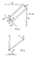
- the joint 30 between the truss 10 and support structure 12 is shown in more detail in Figure 3 and comprises a pivot 31 between the member 19 and an outer member 32 of the structure 12, together with a connection 33 between the member 16 and an inner member 34 of the structure 12.
- the connection 33 is shown in more detail in Figure 5 and comprises a pin 35 through elongate holes 36, 37 in respective elements 38, 39 which are in turn secured to the members 16, 34 respectively.
- the arrangement is such that with a downward load on the truss 10 the elements 38, 39 abut the pin 35 as shown in Figure 5A, the arrangement thus being in compression.
- the truss 10 With a downward load on the truss 10, and by virtue of the pivot joint 14 and the pivotal connections of the support structures 11, 12 to the ground, the truss 10 as a whole is under compression.
- the linkage 17 thus collapses and no compressive load is experienced by the upper members 18, 19 of the truss.
- the elements 38, 39 in both of the joints between the truss and the support structures 11, 12 are urged into the positions shown in Figure 5A.
- the downward load on the truss 10 will cause the tension in the linkage to reduce, the truss as a whole being under compression. Once the tension in the linkage 17 reaches zero, it collapses such that no compressive load is applied to the upper members of the truss.
- the tension in the linkage can be adjusted during building such that the structure acts as a hybrid portal frame.
- the structure acts as a hybrid portal frame.
- predetermined loads When predetermined loads are reached on the portal frame, it converts from a two-pin hybrid portal frame to a three-pin portal frame with no tension in the linkage 17.
- a plurality of portal frames of the type described shall be used as the external supporting structure for a building, wall and roof cladding being secured to inside members of the frames.
- the frames are thereby less liable to buckle in the event of an internal fire in the building.
- the roof cladding also acts to restrain the members 15, 16 of the frames from buckling due to compression.
- Portal frames according to the present invention whereby the members 15, 16 are always in compression are restrained against compressive buckling, and the upper members 18, 19 need not be dimensioned or braced to take compressive loads.
- the structure By pre-stressing the joint arrangement in the truss, snow load deflection is reduced without increasing the member forces due to the snow load.
- the structure will deflect under a snow load, as if it were a two-pin portal frame until the force in the joint arrangement reaches zero. From that point onwards, the structure will act as a three-pin portal frame with the link collapsed. Under wind loads the pre-stress reduces the amount of compression around the knee joint such that the knee joint does not dictate the performance of the structure. The loads of the truss, particularly in the centre, are increased.
- the specific embodiment describes a portal frame structure comprising a horizontal truss with a joint arrangement intermediate its end, in which the joint arrangement is on the upper side of the neutral axis.
- the joint arrangement may be positioned on the lower side of the neutral axis depending on the loads anticipated on the truss.
Landscapes
- Engineering & Computer Science (AREA)
- Architecture (AREA)
- Civil Engineering (AREA)
- Structural Engineering (AREA)
- Rod-Shaped Construction Members (AREA)
- Conveying And Assembling Of Building Elements In Situ (AREA)
- Tents Or Canopies (AREA)
- Bridges Or Land Bridges (AREA)
Applications Claiming Priority (2)
| Application Number | Priority Date | Filing Date | Title |
|---|---|---|---|
| GB8118847 | 1981-06-18 | ||
| GB8118847 | 1981-06-18 |
Publications (2)
| Publication Number | Publication Date |
|---|---|
| EP0068676A2 true EP0068676A2 (fr) | 1983-01-05 |
| EP0068676A3 EP0068676A3 (fr) | 1983-11-09 |
Family
ID=10522619
Family Applications (1)
| Application Number | Title | Priority Date | Filing Date |
|---|---|---|---|
| EP82302969A Withdrawn EP0068676A3 (fr) | 1981-06-18 | 1982-06-09 | Cadres de portiques |
Country Status (8)
| Country | Link |
|---|---|
| EP (1) | EP0068676A3 (fr) |
| AU (1) | AU8495182A (fr) |
| DK (1) | DK276082A (fr) |
| ES (1) | ES513222A0 (fr) |
| FI (1) | FI822011L (fr) |
| NO (1) | NO822012L (fr) |
| PT (1) | PT75082B (fr) |
| ZA (1) | ZA824236B (fr) |
Family Cites Families (6)
| Publication number | Priority date | Publication date | Assignee | Title |
|---|---|---|---|---|
| GB134630A (fr) * | 1900-01-01 | |||
| BE507322A (fr) * | ||||
| DE1091594B (de) * | 1956-04-17 | 1960-10-27 | Emil Mauritz Huennebeck Dipl I | Bauelemente fuer Bruecken, zerlegbare Hallen, Ruestungen od. dgl. |
| DE1434341A1 (de) * | 1961-04-27 | 1968-11-28 | Huennebeck Dipl Ing Hans Joach | Vorrichtung zum Ein- und Ausbau von Tragwerken |
| FR1477768A (fr) * | 1966-03-11 | 1967-04-21 | Ferme métallique | |
| DE2439868A1 (de) * | 1974-08-20 | 1976-03-04 | Fredriksson & Ribring Ab | Zerlegbares gebaeude mit fachwerkboegen, die mehrgelenkig ausgebildet sind, und verfahren zum errichten desselben |
-
1982
- 1982-06-07 FI FI822011A patent/FI822011L/fi not_active Application Discontinuation
- 1982-06-09 EP EP82302969A patent/EP0068676A3/fr not_active Withdrawn
- 1982-06-16 ZA ZA824236A patent/ZA824236B/xx unknown
- 1982-06-17 ES ES513222A patent/ES513222A0/es active Granted
- 1982-06-17 AU AU84951/82A patent/AU8495182A/en not_active Abandoned
- 1982-06-17 NO NO822012A patent/NO822012L/no unknown
- 1982-06-18 DK DK276082A patent/DK276082A/da not_active Application Discontinuation
- 1982-06-18 PT PT75082A patent/PT75082B/fr unknown
Also Published As
| Publication number | Publication date |
|---|---|
| AU8495182A (en) | 1982-12-23 |
| NO822012L (no) | 1982-12-20 |
| PT75082A (fr) | 1982-07-01 |
| EP0068676A3 (fr) | 1983-11-09 |
| ZA824236B (en) | 1983-04-27 |
| DK276082A (da) | 1982-12-19 |
| FI822011A7 (fi) | 1982-12-19 |
| ES8307323A1 (es) | 1983-06-16 |
| FI822011A0 (fi) | 1982-06-07 |
| ES513222A0 (es) | 1983-06-16 |
| FI822011L (fi) | 1982-12-19 |
| PT75082B (fr) | 1984-05-25 |
Similar Documents
| Publication | Publication Date | Title |
|---|---|---|
| KR870009088A (ko) | 트러스 구조물 및 그 건설방법 | |
| US4433700A (en) | Panel structure | |
| US5146719A (en) | Space tension chord arch dome reinforced with tension members and method for building same | |
| CA1116883A (fr) | Forme pour la construction d'un arc | |
| US5159790A (en) | Frame structure | |
| US20030131539A1 (en) | Cantilever support and erectable structures | |
| US4223506A (en) | Frameworks and like structures | |
| US4619099A (en) | Method of erecting arched structures | |
| US4947599A (en) | Trussed girder with pre-tension member therein | |
| GB2097034A (en) | Portal frame structure resistive both upward and downward loads | |
| CN210140764U (zh) | 一种拉索加劲的双折线形桥跨组件 | |
| US4346510A (en) | Pretensioning diagonals in lattice beam-columns | |
| US5134821A (en) | Trussed structure | |
| US10006201B2 (en) | Structural support beam | |
| EP0062047B1 (fr) | Point terminal flexible pour constructions en treillis | |
| RU1791605C (ru) | Устройство дл усилени строительной конструкции | |
| JPH0621474B2 (ja) | トラス架構およびその構築方法 | |
| JPH06212692A (ja) | 門型構造物 | |
| JP3259236B2 (ja) | ノンスラスト大スパン架構法 | |
| JP2754250B2 (ja) | アーチ状型枠支保工 | |
| JPS595731B2 (ja) | 上屋構造物骨組の架構方法 | |
| AU594056B2 (en) | Building truss | |
| RU1791611C (ru) | Каркас сейсмостойкого здани | |
| JP2992496B2 (ja) | 耐震装置 | |
| AU600833B2 (en) | A method of building structures |
Legal Events
| Date | Code | Title | Description |
|---|---|---|---|
| PUAI | Public reference made under article 153(3) epc to a published international application that has entered the european phase |
Free format text: ORIGINAL CODE: 0009012 |
|
| AK | Designated contracting states |
Designated state(s): AT BE CH DE FR IT LI LU NL SE |
|
| PUAL | Search report despatched |
Free format text: ORIGINAL CODE: 0009013 |
|
| AK | Designated contracting states |
Designated state(s): AT BE CH DE FR IT LI LU NL SE |
|
| STAA | Information on the status of an ep patent application or granted ep patent |
Free format text: STATUS: THE APPLICATION IS DEEMED TO BE WITHDRAWN |
|
| 18D | Application deemed to be withdrawn |
Effective date: 19840710 |