EP0068758A2 - Signal-Aufzeichnungs-/Wiedergabegerät - Google Patents
Signal-Aufzeichnungs-/Wiedergabegerät Download PDFInfo
- Publication number
- EP0068758A2 EP0068758A2 EP82303191A EP82303191A EP0068758A2 EP 0068758 A2 EP0068758 A2 EP 0068758A2 EP 82303191 A EP82303191 A EP 82303191A EP 82303191 A EP82303191 A EP 82303191A EP 0068758 A2 EP0068758 A2 EP 0068758A2
- Authority
- EP
- European Patent Office
- Prior art keywords
- tape
- cylinder
- guide means
- rotatable
- pair
- Prior art date
- Legal status (The legal status is an assumption and is not a legal conclusion. Google has not performed a legal analysis and makes no representation as to the accuracy of the status listed.)
- Granted
Links
Images


Classifications
-
- G—PHYSICS
- G11—INFORMATION STORAGE
- G11B—INFORMATION STORAGE BASED ON RELATIVE MOVEMENT BETWEEN RECORD CARRIER AND TRANSDUCER
- G11B15/00—Driving, starting or stopping record carriers of filamentary or web form; Driving both such record carriers and heads; Guiding such record carriers or containers therefor; Control thereof; Control of operating function
- G11B15/02—Control of operating function, e.g. switching from recording to reproducing
- G11B15/16—Control of operating function, e.g. switching from recording to reproducing by sensing presence, absence or position of record carrier or container
-
- G—PHYSICS
- G11—INFORMATION STORAGE
- G11B—INFORMATION STORAGE BASED ON RELATIVE MOVEMENT BETWEEN RECORD CARRIER AND TRANSDUCER
- G11B15/00—Driving, starting or stopping record carriers of filamentary or web form; Driving both such record carriers and heads; Guiding such record carriers or containers therefor; Control thereof; Control of operating function
- G11B15/60—Guiding record carrier
- G11B15/66—Threading; Loading; Automatic self-loading
- G11B15/665—Threading; Loading; Automatic self-loading by extracting loop of record carrier from container
- G11B15/6653—Threading; Loading; Automatic self-loading by extracting loop of record carrier from container to pull the record carrier against drum
- G11B15/6656—Threading; Loading; Automatic self-loading by extracting loop of record carrier from container to pull the record carrier against drum using two-sided extraction, i.e. "M-type"
-
- G—PHYSICS
- G11—INFORMATION STORAGE
- G11B—INFORMATION STORAGE BASED ON RELATIVE MOVEMENT BETWEEN RECORD CARRIER AND TRANSDUCER
- G11B15/00—Driving, starting or stopping record carriers of filamentary or web form; Driving both such record carriers and heads; Guiding such record carriers or containers therefor; Control thereof; Control of operating function
- G11B15/60—Guiding record carrier
- G11B15/61—Guiding record carrier on drum, e.g. drum containing rotating heads
Definitions
- the present invention relates to signal-recording/reproducing apparatus for use with a tape cassette.
- one of the tape guides When the pair of tape guides are in the loading position, one of the tape guides is located at an approaching side of the cylinder where the tape approaches the cylinder and the other tape guide is located at a leaving side of the cylinder where the tape leaves the cylinder, to guide the tape so as to be helically wound around the cylinder over a predetermined angular extent.
- Each of the pair of tape guides includes a non-rotatable guide element.
- an angular over which the tape is in contact with the guide element of the one tape guide is the same as that over which the tape is in contact with the guide. element of the other tape guide.
- the considerable angular extent over which the tape is in contact with the guide element of the other tape guide causes a sliding resistance between the tape and the guide element to be increased to increase a tension applied to the tape.
- the increase in tape tension results in an increase in driving force for driving the tape. This causes the apparatus to be large- sized.
- the increase in tape tension causes a thin tape having its thickness of approximately 10 ⁇ m, for example, to be damaged. That is, if the tension applied to the thin tape is high, the elongation of tape would be increased and the fluctuation in speed of the tape would occur.
- the repeated use of the tape causes a permanent deformation or plastic strain to occur in the tape so that the edges of the tape will be damaged.
- An object of the present invention is to provide signal-recording/reproducing apparatus for use with a tape cassette, which enables the tension on the tape at the leaving side of the cylinder to be reduced.
- signal-recording/reproducing apparatus for use with a tape cassette, comprising: a cylinder having mounted thereon heads for recording and reproducing a signal on and from a magnetic tape within the tape cassette, respectively; a pair of tape guide means movable between an unloading position remote from the cylinder and a loading position adjacent to the cylinder, the tape being withdrawn out of the tape cassette by the pair of tape guide means when they are moved from the unloading position to the loading position, one of the tape guide means being located at an approaching side of the cylinder where the tape approaches the cylinder and the other tape guide means being located at a leaving side of the cylinder where the tape leaves the cylinder when the pair of tape guide means are in the loading position, to guide the tape so as to be helically wound around the cylinder over a predetermined angular extent; and each of the pair of tape guide means including a non-rotatable cylindrical guide element, an angular extent over which the tape is in contact with the guide element of the other tape guide means being
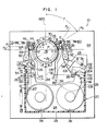
- FIG. 1 there is shown signal-recording/reproducing apparatus for use with a tape cassette in accoudance with an embodiment of the present invention, generally designated by the reference character 10.
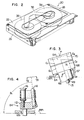
- the tape cassette is generally designated by the reference character 20, and as best shown in Fig. 2, includes a casing having parallel top and bottom wall 22 and 24, a pair of parallel side walls 26, a rear wall 28 and an open front end.
- a supply reel 34 and a take-up reel 36 are rotatably disposed within the casing.
- Guide posts 38, 42 and 44 have their axes perpendicular to the top and bottom walls 22 and 24 of the casing and are located adjacent to one of the pair of the side walls 26.
- Guide posts 46, 48 and 53 corresponding to the guide posts 38, 42 and 44 are located adjacent to the other side wall 26.
- a thin magnetic tape 54 having its thickness of approximately 10 pm, for example, has its ends secured to the supply reel 34 and the take-up reel 36, respectively and is wound around the supply reel 34.
- the tape 54 is guided by the guide posts 38, 44, 46, and 52 and has a portion 56 shown by the phantom line and extending between the guide posts 44 and 52 adjacent to the open front end of the casing of the tape cassette.
- a notch 58 is formed in the bottom wall 24 adjacent to the open front end of the casing.
- the apparatus 10 includes a base frame 64 and a cylinder assembly 65.
- the cylinder assembly 65 includes, as shown in Fig. 3, a fixed hollow shaft 66 extending through the base frame 64, a lower fixed cylinder 68 fixedly mounted on the hollow shaft 66 and seated on an annular projection 67 on the base frame 64, a rotatable shaft 69 extending within the hollow shaft 66 in concentric relation thereto, and an upper rotatable cylinder 70 mounted on the rotatable shaft 69 for rotation therewith.
- the upper rotatable cylinder 70 has a cylindrical peripheral surface identical in diameter with that of the lower fixed cylinder 68 and is axially spaced therefrom.
- An axis 71 of the cylinder assembly 65 is, as shown in Fig. 3, inclined at a predetermined angle 6 ranging from approximately 80 to 88 degrees less than 90 degrees in a plane Po with respect to a first reference plane RP1 which, in the illustrated embodiment, is shown by way of an example as being parallel to the top and bottom walls 22 and 24 of the casing of the tape cassette 20.
- the plane P 0 will be described in detail hereunder.
- a pin 72 for guiding the travelling or movement of the tape Located at an approaching side of the cylinder assembly 65 where the tape 54 approaches the cylinder assembly from the supply reel 34 are a pin 72 for guiding the travelling or movement of the tape, a movable pin 74 abutting against the tape 54 for detecting a tension applied to the tape to control the tape tension under travelling, a pin 76 for guiding the travelling of the tape 54, an erasing head 78 for demagnetizing the entire width of the tape 54, an impedance roller 82 for absorbing and damping the oscillation or vibration of the tape 54 during the travelling thereof and a movable tape guide 84.
- the pins 72 and 74 have their axes perpendicular to the first reference plane RP1 and are fixed to the base frame 64.
- the movable control pin 74 has its axis perpendicular to the first reference plane RP1 and is pivotable around a pivot 87 fixed to the base frame 64 between a loading position shown by the solid line in Fig. 1 and a not-shown unloading position.
- the erasing head 78 is fixed to the base frame 64.
- the impedance roller 82 is supported by the base frame 64 for rotation around an axis perpendicular to the first reference plane RP1.
- a movable tape guide 88 Located at a leaving side of the cylinder assembly 65 where the tape 54 leaves the cylinder assembly toward the take-up reel 36 are a movable tape guide 88, an impedance roller 92 similar to the impedance roller 82, a composite head 94, a pinch roller assembly 96 and a capstan 98.
- the composite head 94 is supported by the base frame so as to be adjustable in position and inclination and comprises a demagnetizing head exclusive for a voice signal track and operative during the recording of the voice signal, a magnetic head for recording/reproducing the voice signal, and a control head for controlling the travelling speed and phase of the tape 54.
- the pinch roller assembly 96 comprises a bracket 102 pivotable around a pivot 104 fixed to the base frame 64 and a pinch roller 106 rotatably mounted on the bracket.
- the capstan 98 is connected to a fly-wheel 108 for rotation therewith and cooperates with the pinch roller 106 to drive or feed the tape 54 at a constant speed.
- the tape guide 84 comprises a mount 112, a non-rotatable cylindrical guide element or guide pin 114 fixed to the mount, and a cylindrical guide element or guide roller 116 rotatably mounted on the mount 112.
- the tape guide 88 comprises a mount 118, a non-rotatable cylindrical guide element or guide pin 122 fixed to the mount, and a cylindrical guide element or guide roller 124 rotatably mounted on the mount 118.
- the tape guides 84 and 88 are movable along respective slots 126 and 128 in the base frame 64 in parallel relation to the first reference plane RP1 between an unloading position shown in Fig. 1 by the phantom line and a loading position shown in Fig. 1 by the solid line.
- the tape guides 84 and 88 are located within the notch 58 of the tape cassette 20 with the portion 56 of the tape 54 positioned between the tape guides and the cylinder assembly 65.
- the tape guides 84 and 88 guide the tape 54 such that the tape is hellically would around the cylinders 68, 70 over a predetermined angular extent more than 180 degrees, for example.
- a mechanism for moving the tape guides 84 and 88 between the loading position and the unloading position may be a well-known mechanism, such as disclosed in U.S. Patent No. 4,138,699, for example.
- the guide pin 114, 122 of each of the tape guides 84 and 88 is located between the cylinder assembly 65 and the guide roller 116, 124.
- the guide rollers 116 and 124 are rotatable around respective axes perpendicularly to the first reference plane RP1.
- the guide pin 114 of the tape guide 84 has its axis inclined at an angle ⁇ 1 with respect to the first reference plane RP1 in a plane substantially parallel to a plane P 1 shown in Fig. 1 and including the axis of the guide pin 114 and the axis of the guide roller 116.
- Fig. 1 As shown in Fig.
- the guide pin 122 has its axis inclined at an angled with respect to the first reference plane RP1 in a plane P 2 shown in Fig. 1 and includes the axis of the guide pin 122 and the axis of the guide roller 124.
- the angle ⁇ 1 is greater than the angle ⁇ 2 .
- the planes P 1 and P 2 shown in Fig. 1 will be described in detail hereinafter.
- a second reference plane RP2 is defined as a plane perpendicular to a third plane P 3 which is perpendicular to the first reference plane RP1 and includes a center point C 1 widthwise of the tape 54 shown in Fig. 3 on a generatrix G 1 shown in Fig. 3 by the phantom line on the cylindrical peripheral surfaces of the cylinders 68, 70 at which the contact of the tape 54 with the cylindrical peripheral surfaces of the cylinders 68, 70 is initiated at the approaching side and a center point C 2 widthwise of the tape 54 shown in Fig. 3 on a generatrix G 2 shown in Fig.
- the second reference plane RP2 is shown as passing through an intersection P of the axis 71 of the cylinder assembly 65 and the top surface of the upper rotatable cylinder 70 for convenience of explanation, but this is not critical or essential.
- the plane P 1 including a straight portion of the tape 54 extending between the roller 116 and pin 114 of the tape guide 84 in the loading position is perpendicular to the first reference plane RP1 and defines an angle ⁇ 1 with respect to the second reference plane RP2.
- the plane P 2 including a straight portion of the tape 54 extending between the roller 124 and the pin 122 of the tape guide 88 in the loading position is perpendicular to the first reference plane RP1 and defines an angle ⁇ 2 with respect to the second reference plane RP2.
- the angle P 2 is less than the angle ⁇ 1 ,
- the angle ⁇ 1 may range from 90 to 120 degrees
- the angle ⁇ 2 may range from 20 to 40 degrees.
- the axis 71 of the cylinder assembly 65 extends at the aforementioned angle 6, as shown in Fig. 3, in the plane P o extending at an angle y with respect to the second reference plane RP2.
- the angle y is approximately 55 to 65 degrees.
- the relation ⁇ 2 ⁇ ⁇ 1 enables the angular extent cx 2 over which the tape 54 is in contact with the non-rotatable pin 122 of the tape guide 88 in the loading position to be decreased as compared with the angular extent ⁇ 1 over which the tape 54 is in contact with the non-rotatable pin 114 of the tape guide 84 in the loading position.
- the wrapping angle ⁇ 2 at which the tape 54 is wound around the pin 122 is decreased as compared with the wrapping angle ⁇ 1 at which the tape 54 is wound around the pin 114.
- the decrease in angular extent ⁇ 2 over which the tape 54 is in contact with the non-rotatable pin 122 causes the frictional sliding resistance between the tape 54 and the pin 122 to be decreased to reduce the increase in a tension applied to the tape 54 in the leaving side.
- the decrease in increase in tape tension causes the driving force for driving the tape to be decreased to enable the apparatus 10 to be small-sized.
- the decrease in tape tension prevents the tape from being excessivly elongated to minimize the fluctuation in tape speed and the permanent deformation or plastic strain of the tape, thereby to minimize that the edges of the tape are damaged.
- Figs. 8-13 show another embodiment of the present invention.
- members and parts having similar functions to those of the first embodiment described with reference to Figs. 1-7 are designated by the same reference characters.
- the embodiment shown in Figs. 8-13 is substantially identical in structure and operation with the first embodiment shown in Figs. 1-7 except that the impedance roller 92 is not disposed in the leaving side and that a second reference plane RP12 perpendicular to a plane P 13 which is perpendicular to a first reference plane RP11 and includes a center point C 11 widthwise of the tape 54 on a generatrix G 11 on the cylindrical peripheral surfaces of the cylinders 68, 70 at which the contact of the tape 54 with the cylindrical surfaces of the cylinders 68, 70 is initiated at the approaching side and a center point C 12 widthwise of the tape 54 on a generatrix G 12 on the cylindrical peripheral surface of the cylinders 68, 70 at which the contact of the tape 54 with the cylindrical peripheral surfaces of the cylinders 68, 70 is ended or terminated is angularly moved by an angle 5 in the clockwise direction with respect to the second reference plane RP2 of the first embodiment shown in Fig.
- the angle 6 is approximately 60 to 80 degrees.
- the angles ⁇ 2 , ⁇ , ⁇ 1 , ⁇ 2 , a 1 and ⁇ 2 shown in Figs. 8-13 are respectively identical with those described with reference to Figs. 1-7.
- the description on members and parts having the same functions as those of the first embodiment will be omitted for simplification, but will be obvious to one skilled in the art.
- the distance through which the tape guide 88 at the leaving side moves from the unloading position shown by the phantom line to the loading position shown by the solid line is shorter than the distance through which the tape guide 84 at the approaching side moves from the unloading position shown by the phantom line to the loading position shown by the solid line.
- the tape guide 88 at the leaving side is located closer to the tape cassette 20 than the tape guide 84 at the approaching side. This enables the path length of the tape 54. at the leaving side to be reduced, and also enables the cylinders 68, 70, capstan 98 and .composite head 94 to be located close to each other, thereby to improve the stable travelling performance of the tape.
- the signal-recording/reproducing apparatus in accordance with the embodiments of the present invention is arranged such that the angular extent or wrapping angle over which the tape 54 is in contact with the non-rotatable guide pin 122 of the tape guide 88 at the leaving side is decreased, the sliding frictional resistance between the guide pin 122 and the tape 54 is reduced, and the driving force required for driving the tape is also decreased to enable the apparatus to be small-sized.
- the decrease in sliding frictional resistance minimizes the tape elongation to minimize the damage on the edges of the tape.
- the upper cylinder 70 is rotatable and that the cylinder assembly 65 has its axis 71 inclined at an angle less than 90 degrees with respect to the first reference plane RP1, RP11.
- the upper cylinder 70 may be fixedly connected to the lower cylinder 68 against rotation relative thereto, and the axis 71 of the cylinder assembly 65 may be perpendicular to the first reference plane RP1, RP11.
- the inclination of the guide pin 114, 122 of each of the tape guides 84 and 88 with respect to the first reference plane RP1, RP11 depends upon the inclination of the axis 71 of the cylinder assembly 65 with respect to the first reference plane RP1, RP11.
- the tape guides 84 and 88 may take their loading positions different in level from their unloading position with the angles of planes extending between the loading positions and the unloading positions with respect to the first reference plane RP11 being varied dependent upon the variation of the inclination angle of the axis 71.
Landscapes
- Recording Or Reproducing By Magnetic Means (AREA)
- Registering, Tensioning, Guiding Webs, And Rollers Therefor (AREA)
- Optical Recording Or Reproduction (AREA)
- Steroid Compounds (AREA)
- Signal Processing Not Specific To The Method Of Recording And Reproducing (AREA)
- Adjustment Of The Magnetic Head Position Track Following On Tapes (AREA)
- Input Circuits Of Receivers And Coupling Of Receivers And Audio Equipment (AREA)
- Traffic Control Systems (AREA)
- Automatic Tape Cassette Changers (AREA)
Priority Applications (1)
| Application Number | Priority Date | Filing Date | Title |
|---|---|---|---|
| AT82303191T ATE25441T1 (de) | 1981-06-24 | 1982-06-18 | Signal-aufzeichnungs-/wiedergabegeraet. |
Applications Claiming Priority (2)
| Application Number | Priority Date | Filing Date | Title |
|---|---|---|---|
| JP56096663A JPS57212649A (en) | 1981-06-24 | 1981-06-24 | Magnetic recording and reproducing device |
| JP96663/81 | 1981-06-24 |
Publications (3)
| Publication Number | Publication Date |
|---|---|
| EP0068758A2 true EP0068758A2 (de) | 1983-01-05 |
| EP0068758A3 EP0068758A3 (en) | 1983-11-23 |
| EP0068758B1 EP0068758B1 (de) | 1987-02-04 |
Family
ID=14171052
Family Applications (1)
| Application Number | Title | Priority Date | Filing Date |
|---|---|---|---|
| EP82303191A Expired EP0068758B1 (de) | 1981-06-24 | 1982-06-18 | Signal-Aufzeichnungs-/Wiedergabegerät |
Country Status (8)
| Country | Link |
|---|---|
| US (1) | US4583137A (de) |
| EP (1) | EP0068758B1 (de) |
| JP (1) | JPS57212649A (de) |
| KR (1) | KR880001227B1 (de) |
| AT (1) | ATE25441T1 (de) |
| BR (1) | BR8203641A (de) |
| CA (1) | CA1181171A (de) |
| DE (1) | DE3275418D1 (de) |
Cited By (4)
| Publication number | Priority date | Publication date | Assignee | Title |
|---|---|---|---|---|
| DE3435006A1 (de) * | 1983-09-24 | 1985-04-25 | Sony Corp., Tokio/Tokyo | Magnetische aufnahme- und wiedergabeanordnung |
| EP0240925A3 (en) * | 1986-04-02 | 1989-06-28 | Victor Company Of Japan, Limited | Tape loading of magnetic recording/reproducing apparatus |
| EP0375672A3 (de) * | 1985-02-14 | 1990-12-05 | Sony Corporation | Aufzeichnungs- und/oder Wiedergabegerät mit einem drehbaren Kopf zur Aufzeichnung und Wiedergabe von Signalen auf einer Magnetbandkassette |
| EP1607958A3 (de) * | 2004-06-18 | 2008-02-27 | Samsung Electronics Co, Ltd | Bandlaufwerk |
Families Citing this family (11)
| Publication number | Priority date | Publication date | Assignee | Title |
|---|---|---|---|---|
| JPS5979459A (ja) * | 1982-10-29 | 1984-05-08 | Victor Co Of Japan Ltd | 磁気記録再生装置 |
| JPH0690828B2 (ja) * | 1983-09-14 | 1994-11-14 | 日本ビクター株式会社 | 磁気記録再生装置 |
| US4752844A (en) * | 1984-03-31 | 1988-06-21 | Alpine Electronics Inc. | Tape cassette loading device in a magnetic tape recorder-reproducer apparatus |
| US4750062A (en) * | 1984-04-19 | 1988-06-07 | Alpine Electronics Ltd. | Rotatable tape loading device in a magnetic tape recorder-reproducer apparatus |
| JPH0654578B2 (ja) * | 1984-12-19 | 1994-07-20 | ソニー株式会社 | 記録再生装置 |
| JPS63168864A (ja) * | 1986-12-30 | 1988-07-12 | Kazuo Hashimoto | ダブルテ−プ式ビデオカセツトテ−プレコ−ダ |
| US5184259A (en) * | 1988-07-05 | 1993-02-02 | U.S. Philips Corporation | Helical-scan magnetic tape apparatus having a tape-transport path with twisting path-sections for tape-path correction |
| DE69033148T2 (de) * | 1989-03-31 | 1999-12-09 | Sony Corp., Tokio/Tokyo | System zur Gewährleistung eines stabilen Bandlaufs bei Aufzeichnung und/oder Wiedergabe |
| JP2965456B2 (ja) * | 1994-03-23 | 1999-10-18 | シャープ株式会社 | 磁気記録再生装置 |
| JP3541556B2 (ja) * | 1996-04-09 | 2004-07-14 | ソニー株式会社 | 磁気記録再生装置 |
| US7195189B2 (en) * | 2005-02-01 | 2007-03-27 | International Business Machines Corporation | Tape system with an isolated load/unload tape path |
Family Cites Families (12)
| Publication number | Priority date | Publication date | Assignee | Title |
|---|---|---|---|---|
| US894262A (en) * | 1906-07-26 | 1908-07-28 | Albert G Ellinwood | Vegetable-harvesting machine. |
| US3319014A (en) * | 1961-11-29 | 1967-05-09 | Matsushita Electric Industrial Co Ltd | Tape guide arrangement for use in magnetic video tape recording apparatus |
| NL169794C (nl) * | 1972-02-04 | 1982-08-16 | Nippon Electric Co | Beeldbandopneem- en/of weergeeftoestel met middelen voor het invoeren van de magneetband vanuit een cassette. |
| JPS5220249Y2 (de) * | 1972-05-04 | 1977-05-10 | ||
| JPS49144216U (de) * | 1973-04-12 | 1974-12-12 | ||
| JPS5545593Y2 (de) * | 1975-04-14 | 1980-10-25 | ||
| JPS5731390Y2 (de) * | 1975-06-23 | 1982-07-09 | ||
| JPS52134410A (en) * | 1976-05-04 | 1977-11-10 | Matsushita Electric Ind Co Ltd | Rotary head tape magnetic record/reproduce device |
| JPS5827580B2 (ja) * | 1976-05-04 | 1983-06-10 | 松下電器産業株式会社 | 磁気記録再生装置 |
| US4138699A (en) * | 1976-06-04 | 1979-02-06 | Victor Company Of Japan, Ltd. | Automatic tape loading type recording and/or reproducing apparatus |
| JPS604300Y2 (ja) * | 1978-06-12 | 1985-02-06 | 三洋電機株式会社 | ロ−デイング機構 |
| JPS57191865A (en) * | 1981-05-21 | 1982-11-25 | Hitachi Ltd | Magnetic recorder and reproducer |
-
1981
- 1981-06-24 JP JP56096663A patent/JPS57212649A/ja active Granted
-
1982
- 1982-06-15 KR KR8202671A patent/KR880001227B1/ko not_active Expired
- 1982-06-16 US US06/389,076 patent/US4583137A/en not_active Expired - Lifetime
- 1982-06-18 AT AT82303191T patent/ATE25441T1/de not_active IP Right Cessation
- 1982-06-18 EP EP82303191A patent/EP0068758B1/de not_active Expired
- 1982-06-18 DE DE8282303191T patent/DE3275418D1/de not_active Expired
- 1982-06-22 BR BR8203641A patent/BR8203641A/pt unknown
- 1982-06-23 CA CA000405851A patent/CA1181171A/en not_active Expired
Cited By (4)
| Publication number | Priority date | Publication date | Assignee | Title |
|---|---|---|---|---|
| DE3435006A1 (de) * | 1983-09-24 | 1985-04-25 | Sony Corp., Tokio/Tokyo | Magnetische aufnahme- und wiedergabeanordnung |
| EP0375672A3 (de) * | 1985-02-14 | 1990-12-05 | Sony Corporation | Aufzeichnungs- und/oder Wiedergabegerät mit einem drehbaren Kopf zur Aufzeichnung und Wiedergabe von Signalen auf einer Magnetbandkassette |
| EP0240925A3 (en) * | 1986-04-02 | 1989-06-28 | Victor Company Of Japan, Limited | Tape loading of magnetic recording/reproducing apparatus |
| EP1607958A3 (de) * | 2004-06-18 | 2008-02-27 | Samsung Electronics Co, Ltd | Bandlaufwerk |
Also Published As
| Publication number | Publication date |
|---|---|
| KR880001227B1 (ko) | 1988-07-11 |
| JPS57212649A (en) | 1982-12-27 |
| EP0068758A3 (en) | 1983-11-23 |
| EP0068758B1 (de) | 1987-02-04 |
| CA1181171A (en) | 1985-01-15 |
| US4583137A (en) | 1986-04-15 |
| DE3275418D1 (en) | 1987-03-12 |
| ATE25441T1 (de) | 1987-02-15 |
| BR8203641A (pt) | 1983-06-14 |
| KR840000925A (ko) | 1984-03-26 |
| JPH0449180B2 (de) | 1992-08-10 |
Similar Documents
| Publication | Publication Date | Title |
|---|---|---|
| US4837646A (en) | Tape guide apparatus for helically wound tape | |
| EP0068758A2 (de) | Signal-Aufzeichnungs-/Wiedergabegerät | |
| CA1198815A (en) | Magnetic recording and playback apparatus | |
| JPH0678158B2 (ja) | テープリール | |
| KR940006386B1 (ko) | 자기 기록 재생장치의 테이프 텐션 제어장치 | |
| JPH0644369B2 (ja) | 磁気記録再生装置 | |
| JPH06508711A (ja) | 単方向テープ引張り要素およびそれを使用する方法 | |
| US4823222A (en) | Webbed scanner window | |
| EP0443426B1 (de) | Bandführungsmechanismus für eine Aufzeichnungs- und Wiedergabevorrichtung | |
| EP0531751B1 (de) | Magnetisches Aufzeichnungs-/Wiedergabegerät | |
| JPH0536169A (ja) | 磁気記録再生装置のテープ走行機構 | |
| KR950003079B1 (ko) | 자기기록재생기의 테이프 주행계 | |
| US5523905A (en) | Recording or reproducing apparatus with tape guide members providing a space to receive a tape-end sensor | |
| JP2614506B2 (ja) | 磁気記録再生装置 | |
| EP0329345A2 (de) | Magnetisches Aufnahme- und Wiedergabegerät | |
| JP2778280B2 (ja) | 磁気記録再生装置 | |
| JP2605835Y2 (ja) | 磁気記録再生装置 | |
| JPS59186162A (ja) | 磁気記録再生装置 | |
| CA1240393A (en) | Tape guide mechanism for a magnetic recording/reproducing apparatus | |
| JPH0222824Y2 (de) | ||
| JPH03238650A (ja) | 磁気記録再生装置のテープローディング機構 | |
| JPS61217956A (ja) | 磁気記録再生装置 | |
| JP2001297417A (ja) | 磁気ヘッド装置 | |
| JPH0435822B2 (de) | ||
| JPH09115213A (ja) | テープガイド装置 |
Legal Events
| Date | Code | Title | Description |
|---|---|---|---|
| PUAI | Public reference made under article 153(3) epc to a published international application that has entered the european phase |
Free format text: ORIGINAL CODE: 0009012 |
|
| AK | Designated contracting states |
Designated state(s): AT DE FR GB IT |
|
| PUAL | Search report despatched |
Free format text: ORIGINAL CODE: 0009013 |
|
| AK | Designated contracting states |
Designated state(s): AT DE FR GB IT |
|
| 17P | Request for examination filed |
Effective date: 19840303 |
|
| GRAA | (expected) grant |
Free format text: ORIGINAL CODE: 0009210 |
|
| AK | Designated contracting states |
Kind code of ref document: B1 Designated state(s): AT DE FR GB IT |
|
| REF | Corresponds to: |
Ref document number: 25441 Country of ref document: AT Date of ref document: 19870215 Kind code of ref document: T |
|
| REF | Corresponds to: |
Ref document number: 3275418 Country of ref document: DE Date of ref document: 19870312 |
|
| ITF | It: translation for a ep patent filed | ||
| ET | Fr: translation filed | ||
| PLBE | No opposition filed within time limit |
Free format text: ORIGINAL CODE: 0009261 |
|
| STAA | Information on the status of an ep patent application or granted ep patent |
Free format text: STATUS: NO OPPOSITION FILED WITHIN TIME LIMIT |
|
| 26N | No opposition filed | ||
| PGFP | Annual fee paid to national office [announced via postgrant information from national office to epo] |
Ref country code: FR Payment date: 19910517 Year of fee payment: 10 |
|
| PGFP | Annual fee paid to national office [announced via postgrant information from national office to epo] |
Ref country code: AT Payment date: 19910523 Year of fee payment: 10 |
|
| ITTA | It: last paid annual fee | ||
| PG25 | Lapsed in a contracting state [announced via postgrant information from national office to epo] |
Ref country code: AT Effective date: 19920618 |
|
| PG25 | Lapsed in a contracting state [announced via postgrant information from national office to epo] |
Ref country code: FR Effective date: 19930226 |
|
| REG | Reference to a national code |
Ref country code: FR Ref legal event code: ST |
|
| PGFP | Annual fee paid to national office [announced via postgrant information from national office to epo] |
Ref country code: GB Payment date: 19990616 Year of fee payment: 18 |
|
| PGFP | Annual fee paid to national office [announced via postgrant information from national office to epo] |
Ref country code: DE Payment date: 19990824 Year of fee payment: 18 |
|
| PG25 | Lapsed in a contracting state [announced via postgrant information from national office to epo] |
Ref country code: GB Free format text: LAPSE BECAUSE OF NON-PAYMENT OF DUE FEES Effective date: 20000618 |
|
| GBPC | Gb: european patent ceased through non-payment of renewal fee |
Effective date: 20000618 |
|
| PG25 | Lapsed in a contracting state [announced via postgrant information from national office to epo] |
Ref country code: DE Free format text: LAPSE BECAUSE OF NON-PAYMENT OF DUE FEES Effective date: 20010403 |