EP0068760B1 - Einrichtung zur magnetischen Konditionierung von Wasser - Google Patents
Einrichtung zur magnetischen Konditionierung von Wasser Download PDFInfo
- Publication number
- EP0068760B1 EP0068760B1 EP82303194A EP82303194A EP0068760B1 EP 0068760 B1 EP0068760 B1 EP 0068760B1 EP 82303194 A EP82303194 A EP 82303194A EP 82303194 A EP82303194 A EP 82303194A EP 0068760 B1 EP0068760 B1 EP 0068760B1
- Authority
- EP
- European Patent Office
- Prior art keywords
- water
- gap
- housing
- magnetic field
- magnetic
- Prior art date
- Legal status (The legal status is an assumption and is not a legal conclusion. Google has not performed a legal analysis and makes no representation as to the accuracy of the status listed.)
- Expired
Links
- XLYOFNOQVPJJNP-UHFFFAOYSA-N water Substances O XLYOFNOQVPJJNP-UHFFFAOYSA-N 0.000 claims abstract description 55
- 230000008859 change Effects 0.000 claims description 2
- 230000001681 protective effect Effects 0.000 claims description 2
- 238000007789 sealing Methods 0.000 abstract 1
- 229910001369 Brass Inorganic materials 0.000 description 5
- 239000010951 brass Substances 0.000 description 5
- 229910052500 inorganic mineral Inorganic materials 0.000 description 5
- 239000011707 mineral Substances 0.000 description 5
- 239000002245 particle Substances 0.000 description 5
- 230000003750 conditioning effect Effects 0.000 description 4
- 230000000694 effects Effects 0.000 description 4
- 239000000463 material Substances 0.000 description 4
- 229910000831 Steel Inorganic materials 0.000 description 3
- 230000008901 benefit Effects 0.000 description 3
- 230000007797 corrosion Effects 0.000 description 3
- 238000005260 corrosion Methods 0.000 description 3
- 239000013505 freshwater Substances 0.000 description 3
- 239000004033 plastic Substances 0.000 description 3
- 229920003023 plastic Polymers 0.000 description 3
- 239000010959 steel Substances 0.000 description 3
- 238000010276 construction Methods 0.000 description 2
- 238000009434 installation Methods 0.000 description 2
- 150000002500 ions Chemical class 0.000 description 2
- 239000007787 solid Substances 0.000 description 2
- 229910001220 stainless steel Inorganic materials 0.000 description 2
- 239000010935 stainless steel Substances 0.000 description 2
- OYPRJOBELJOOCE-UHFFFAOYSA-N Calcium Chemical compound [Ca] OYPRJOBELJOOCE-UHFFFAOYSA-N 0.000 description 1
- FYYHWMGAXLPEAU-UHFFFAOYSA-N Magnesium Chemical compound [Mg] FYYHWMGAXLPEAU-UHFFFAOYSA-N 0.000 description 1
- 230000009471 action Effects 0.000 description 1
- 229910000828 alnico Inorganic materials 0.000 description 1
- 229910052782 aluminium Inorganic materials 0.000 description 1
- 229910052791 calcium Inorganic materials 0.000 description 1
- 239000011575 calcium Substances 0.000 description 1
- 230000015556 catabolic process Effects 0.000 description 1
- 239000013078 crystal Substances 0.000 description 1
- 230000007812 deficiency Effects 0.000 description 1
- 238000006731 degradation reaction Methods 0.000 description 1
- 238000001914 filtration Methods 0.000 description 1
- 239000012530 fluid Substances 0.000 description 1
- 230000004907 flux Effects 0.000 description 1
- 230000007773 growth pattern Effects 0.000 description 1
- 229910052749 magnesium Inorganic materials 0.000 description 1
- 239000011777 magnesium Substances 0.000 description 1
- 239000012528 membrane Substances 0.000 description 1
- 239000002184 metal Substances 0.000 description 1
- 229910052751 metal Inorganic materials 0.000 description 1
- 238000009428 plumbing Methods 0.000 description 1
- 229920001084 poly(chloroprene) Polymers 0.000 description 1
- 239000002244 precipitate Substances 0.000 description 1
- 238000001556 precipitation Methods 0.000 description 1
- 230000009467 reduction Effects 0.000 description 1
- 238000000926 separation method Methods 0.000 description 1
- 239000011343 solid material Substances 0.000 description 1
- 230000007480 spreading Effects 0.000 description 1
- 229920003051 synthetic elastomer Polymers 0.000 description 1
- 239000005061 synthetic rubber Substances 0.000 description 1
Images

Classifications
-
- C—CHEMISTRY; METALLURGY
- C02—TREATMENT OF WATER, WASTE WATER, SEWAGE, OR SLUDGE
- C02F—TREATMENT OF WATER, WASTE WATER, SEWAGE, OR SLUDGE
- C02F1/00—Treatment of water, waste water, or sewage
- C02F1/48—Treatment of water, waste water, or sewage with magnetic or electric fields
- C02F1/481—Treatment of water, waste water, or sewage with magnetic or electric fields using permanent magnets
Definitions
- the present invention relates to magnetic water-conditioning devices in which the water to be treated flows through a flow gap of adjustable width across which a magnetic field acts which is generated by a permanent magnet.
- the magnetic water conditioning device has also been found useful for removing existing scale which has been previously deposited in the conduit prior to installation of the magnetic water conditioner.
- the magnetic water conditioning devices disclosed in these various references have several serious shortcomings and two major shortcomings.
- the permanent magnets utilized in the devices are not effectively insulated from the water passing through the devices and consequently solid material tends to deposit on the magnets, and the magnets tend to corrode over a period of time, thereby reducing their effectiveness.
- none of the magnetic devices disclosed has any inherent capability to deal with changing water flow rates or water pressures, or to vary the force of the magnetic field in relation to the flow-rate of water through the device, without disassembling of the device and manual internal adjustment.
- AQUA-DIAL 15 An adjustable magnetic water conditioning solid under the trade mark AQUA-DIAL 15 is available from BSAL guitarist-upon-Thames, Surrey, England. However, the adjustability feature in that device is located internally within the device and hence the device must be disassembled in order to make any necessary adjustments. Additionally, the device does not provide a built-in Venturi effect.
- Patent Specification GB ⁇ A ⁇ 2023116 describes a magnetic water-conditioning device in which a permanent magnet providing the field across the flow gap is isolated from fluid being treated in the device by means of a thin separation membrane made of non-magnetic stainless steel.
- the device in accordance with the present invention is characterized in that the permanent magnet is surrounded by a protective sleeve closed at one end by an adjusting cap and at the other by a pole piece to form a plug body in which the magnet is enclosed for protection against water flowing through the gap, the pole piece defines one side of the gap and the plug body is adjustably mounted in a housing and coupled to means which enable the position of the pole-piece in the housing to be adjusted from outside the housing to control the gap size and thereby change simultaneously the flow rate and the strength of the magnetic field
- the conditioning device optionally can be equipped internally or externally with a water filtering device.
- the device is also preferably designed to provide a Venturi-type gap in the area where the magnetic field is concentrated thereby tending to keep the gap free of foreign particles.
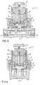
- the magnetic water conditioner 1 is constructed of a hollow housing 2 having a water inlet 3 and a water outlet 4. Inlet 3 and outlet 4 are female threaded to accommodate standard size water piping. The direction of water flow through the housing 2 is indicated by the directional arrows.
- the internal cup 5 houses a permanent magnet 7, which preferably should be the strongest permanent magnet available, for example, the type of magnets described as "supermagnets" and sold under the names or trade marks Alcomax or Alnico.
- Magnet 7 is enclosed by means of a hollow cylindrical magnet housing 8 which at its bottom region contacts magnet extension 9, and at its top region contacts adjusting cap 11.
- the magnet 7, magnet housing 8, and magnet extension 9 are held rigidly in place against adjusting cap 11 by means of screw 10.
- Adjusting cap 11 can be adjusted upwardly or downwardly within the distance of adjusting threads 13, which are machined within the inside surface of the upper region of internal cup 5.
- Adjusting cap 11 can have calibrations on the top surface thereof indicating various positions for the cap ranging from 0 to 9. The position of the adjusting cap 11 is indicated by means of dial pin 14. A pin stop 15 is mounted at the end of dial pin 14 and, when in place, prevents anyone intending to adjust the setting of the adjusting cap 11 from deliberately or inadvertently completely screwing cap 11 out of threads 13, and thereby breaking the magnetic circuit and reducing the effectiveness of the device.
- a number of O-rings 16 are positioned at various critical positions throughout the internal regions of the water conditioner 1 in order to prevent water under high pressure leaking between the interfaces of the various components making up the water conditioner 1.
- a magnetic field created by magnet 7, and transmitted through magnet extension 9 passes between seat interface 17 and valve seat 18.
- the distance between seat interface 17 of magnet extension 9 and valve seat 18 at the bottom of cup “5 can be adjusted to provide different settings. Accordingly, the length and hence strength of the magnetic field can be adjusted within certain limits. Furthermore, since the distance between seat interface 17 and valve seat 18 can be adjusted, the rate of water flow passing through housing 2 can also be adjusted.
- the construction shown has the advantage that by means of cooperating carefully machined bevelled faces, seat interface 17 can be closed completely down upon valve seat 18, thereby completely stopping the flow of water through the housing 2. Furthermore, as the rate of water flow through housing 2 is reduced by closing the gap between seat interface 17 and valve seat 18, the reduction in the gap has the effect of increasing the magnetic flux or gauss-force of the magnetic field existing between seat interface 17 and valve seat 18. This is highly advantageous because studies appear to show that for best results, higher magnetic forces should be used for reduced rates of water flow.
- the gap design between interface 17 and seat 18 is advantageous also because it tends to provide a Venturi-effect on the water at this location and thereby tends to keep the gap area free of foreign particles.
- FIGURES 3 and 4 depict an alternative embodiment of magnetic water conditioner 1.
- the components of the alternative embodiment are basically the same as those discussed above in connection with the embodiment shown in FIGURES 1 and 2.
- the design of magnetic extension 9 is different from that shown in FIGURES 1 and 2.
- Seat interface 19 in the alternative embodiment shown in FIGURES 3 and 4 is machined to have a horizontal planar face.
- valve seat 20 at the bottom region of cup 5 is not cupped as shown in the embodiment depicted in FIGURES 1 and 2, but is machined to have a horizontal planar face corresponding to the face of interface 19.
- the magnetic field passes vertically between seat interface 19 and valve seat 20.
- the water passing through the conditioner 1 passes through the magnetic field immediately before passing downwardly through the exit-port openings that are located at the bottom region of internal cup 5.
- the distance between seat interface 19 and valve seat 20 can be adjusted within prescribed limits, and indeed, closed completely to adjust the rate of water flow through the housing and also the intensity of the magnetic field.
- Interface 17 and valve seat 18, shown in the embodiment depicted in FIGURES 1 and 2 is preferred for completely stopping the flow of water through the conditioner 1.
- the angled orientation of the seat interface 17 with valve seat 18 provides greater surface area and superior closing action.
- this arrangement has the effect of spreading the magnetic field over a greater area but acts to keep the magnetic gap free of foreign particles.
- the embodiment shown in FIGURES 3 and 4 has the advantage that the magnetic field can be highly localized between seat face 19 and valve seat 20.
- housing 2 can be constructed of brass or a plastic having a high pressure capability as dictated by plumbing codes in effect in the area where the conditioner 1 is installed.
- the magnetic circuit components, internal cup 5, magnet extension 7 and adjusting cap 11 are preferably constructed of stainless steel, since these components are subject to water exposure and should be corrosion resistant.
- Collar 6 can be constructed of brass, steel or a strong thermostatic plastic having good dimensional stability and high pressure capabilities.
- the magnet housing 8 can be constructed of either brass or strong pressure and corrosion resistant plastic or steel. All O-rings 16 are constructed of a suitable elastic degradation-resistant-material such as synthetic rubber, possibly Neoprene. Screw 10, dial pin 14 and pin stop 15 can be constructed of brass.
- Handle 12 can be constructed of some suitable metal such as cast- aluminum, brass or steel.
- the magnetic water-treating device described firstly, insulates the permanent magnets housed in the unit from the water that passes through the device, thereby eliminating solid deposits and corrosion of the magnets, and, secondly, permits ready manual adjustment in order to accommodate different water flow rates, without having to disassemble the device in any way. Varying water flow rates can be encountered either in one application, or when the device is installed in various applications involving differing water pressures and water flow rates.
- the strength and length of the magnetic field can be adjusted to. suit various applications.
- the magnetic field can be adjusted from about 6,000 Gauss when the device is in fully open position to 12,000 Gauss when the device is almost completely closed. This feature is advantageous because a higher intensity magnetic field is preferred for slow flow rates.
- a further significant advantage of the device is that manual adjustments can be made externally simply by turning an externally located handle according to calibration on the dial mounted under the handle. This eliminates the necessity of disassembling the device in order to make flow-rate adjustments. It also permits adjustments to be made quickly and frequently.
Landscapes
- Life Sciences & Earth Sciences (AREA)
- Hydrology & Water Resources (AREA)
- Engineering & Computer Science (AREA)
- Environmental & Geological Engineering (AREA)
- Water Supply & Treatment (AREA)
- Chemical & Material Sciences (AREA)
- Organic Chemistry (AREA)
- Water Treatment By Electricity Or Magnetism (AREA)
- Indication Of The Valve Opening Or Closing Status (AREA)
Claims (5)
Priority Applications (1)
| Application Number | Priority Date | Filing Date | Title |
|---|---|---|---|
| AT82303194T ATE15878T1 (de) | 1981-06-19 | 1982-06-18 | Einrichtung zur magnetischen konditionierung von wasser. |
Applications Claiming Priority (2)
| Application Number | Priority Date | Filing Date | Title |
|---|---|---|---|
| CA000380251A CA1184532A (en) | 1981-06-19 | 1981-06-19 | Magnetic water conditioning device |
| CA380251 | 1981-06-19 |
Publications (2)
| Publication Number | Publication Date |
|---|---|
| EP0068760A1 EP0068760A1 (de) | 1983-01-05 |
| EP0068760B1 true EP0068760B1 (de) | 1985-10-02 |
Family
ID=4120279
Family Applications (1)
| Application Number | Title | Priority Date | Filing Date |
|---|---|---|---|
| EP82303194A Expired EP0068760B1 (de) | 1981-06-19 | 1982-06-18 | Einrichtung zur magnetischen Konditionierung von Wasser |
Country Status (5)
| Country | Link |
|---|---|
| US (1) | US4422933A (de) |
| EP (1) | EP0068760B1 (de) |
| AT (1) | ATE15878T1 (de) |
| CA (1) | CA1184532A (de) |
| DE (1) | DE3266668D1 (de) |
Cited By (5)
| Publication number | Priority date | Publication date | Assignee | Title |
|---|---|---|---|---|
| US6956763B2 (en) | 2003-06-27 | 2005-10-18 | Freescale Semiconductor, Inc. | MRAM element and methods for writing the MRAM element |
| US6967366B2 (en) | 2003-08-25 | 2005-11-22 | Freescale Semiconductor, Inc. | Magnetoresistive random access memory with reduced switching field variation |
| US7129098B2 (en) | 2004-11-24 | 2006-10-31 | Freescale Semiconductor, Inc. | Reduced power magnetoresistive random access memory elements |
| US7184300B2 (en) | 2001-10-16 | 2007-02-27 | Freescale Semiconductor, Inc. | Magneto resistance random access memory element |
| US7465589B2 (en) | 2002-07-17 | 2008-12-16 | Everspin Technologies, Inc. | Multi-state magnetoresistance random access cell with improved memory storage density |
Families Citing this family (21)
| Publication number | Priority date | Publication date | Assignee | Title |
|---|---|---|---|---|
| JPS589560U (ja) * | 1981-07-13 | 1983-01-21 | トヨタ自動車株式会社 | トランスミツシヨンのハウジング |
| IN164745B (de) * | 1984-05-11 | 1989-05-20 | Stamicarbon | |
| US4664796A (en) * | 1985-09-16 | 1987-05-12 | Coulter Electronics, Inc. | Flux diverting flow chamber for high gradient magnetic separation of particles from a liquid medium |
| NO159162C (no) * | 1986-07-29 | 1988-12-07 | Fjeldsend As Olaf | Apparat for magnetisk paavirkning av stroemmende vaeske. |
| DK158576C (da) * | 1987-04-09 | 1990-11-12 | Nordrill As | Apparat til magnetisk paavirkning af stroemmende vaeske |
| IL91014A (en) * | 1989-07-17 | 1994-01-25 | Lin Israel J | Magnetic treatment of water used for agricultural purpose |
| DE4107708C2 (de) * | 1991-03-09 | 1995-08-17 | Judo Wasseraufbereitung | Verfahren und Vorrichtung zum Behandeln von Wasser gegen Kalkablagerung |
| ES2085824B1 (es) * | 1993-02-04 | 1998-02-16 | Torre Barreiro Jose Luis De | Mejoras introducidas en acondicionadores magneticos para tratamiento de liquidos. |
| DE4308416A1 (de) * | 1993-03-17 | 1994-09-22 | Werner Zink | Vorrichtung zur magnetischen Behandlung von strömenden Flüssigkeiten, anorganischen und/oder organischen Gemischen oder Lösungen, insbesondere von Wasser |
| WO1996015070A1 (en) * | 1994-11-14 | 1996-05-23 | Vladimir Igorevich Shulyatikov | Device for the magnetic treatment of liquid |
| GB2311945B (en) * | 1996-04-12 | 2001-01-17 | Liff Ind Ltd | Magnetic treatment device for liquids |
| US6221245B1 (en) * | 1999-12-13 | 2001-04-24 | Michael H. Colburn | Non-chemical scale prevention and chlorine removal water filter |
| US7004153B2 (en) * | 2003-06-13 | 2006-02-28 | Wout Lisseveld | Fuel treatment device using a magnetic field |
| WO2005000520A1 (ja) * | 2003-06-26 | 2005-01-06 | Hirata Corporation | ピストンリング装着装置及び方法 |
| CA2472285C (en) * | 2003-07-16 | 2012-08-28 | Frederick J. Dart | Water treatment apparatus and method |
| US9187344B2 (en) | 2008-08-01 | 2015-11-17 | Silver Bullet Water Treatment Company, Llc | Water treatment device and methods of use |
| ES2657897T3 (es) | 2011-04-12 | 2018-03-07 | Silver Bullet Water Treatment Company, Llc | Sistemas y método de tratamiento de agua mediante radiación UV |
| US9475718B2 (en) * | 2013-05-06 | 2016-10-25 | John O. Richmond | Water purification system and process with water pretreatment apparatus |
| US20150376044A1 (en) * | 2013-05-06 | 2015-12-31 | Mary M.F. Richmond | Water purification process with water pretratment |
| US20160083275A1 (en) * | 2014-09-19 | 2016-03-24 | Aardvark Ip Holding, Llc | Water treatment systems and methods |
| CN114162883B (zh) * | 2020-11-09 | 2024-12-10 | 佛山市美的清湖净水设备有限公司 | 净水设备的出水装置和具有其的净水设备 |
Family Cites Families (7)
| Publication number | Priority date | Publication date | Assignee | Title |
|---|---|---|---|---|
| US1934314A (en) * | 1930-12-10 | 1933-11-07 | James J Lawier | Valve construction |
| US2797704A (en) * | 1953-02-04 | 1957-07-02 | John J Mcdermott | Check valve |
| NL226428A (de) * | 1957-04-02 | |||
| SU143813A1 (ru) * | 1961-07-17 | 1961-11-30 | В.П. Михеев | Устройство дл магнитной обработки воды |
| NO131006C (de) * | 1973-07-10 | 1975-03-19 | Fjeldsend As Olaf | |
| US4265754A (en) * | 1977-12-12 | 1981-05-05 | Bon Aqua, Inc. | Water treating apparatus and methods |
| GB2023116B (en) * | 1978-05-30 | 1982-10-27 | Strutt Agencies Ltd B | Apparatus for the magnetic treatment of liquids |
-
1981
- 1981-06-19 CA CA000380251A patent/CA1184532A/en not_active Expired
- 1981-10-26 US US06/314,729 patent/US4422933A/en not_active Expired - Lifetime
-
1982
- 1982-06-18 EP EP82303194A patent/EP0068760B1/de not_active Expired
- 1982-06-18 AT AT82303194T patent/ATE15878T1/de not_active IP Right Cessation
- 1982-06-18 DE DE8282303194T patent/DE3266668D1/de not_active Expired
Cited By (5)
| Publication number | Priority date | Publication date | Assignee | Title |
|---|---|---|---|---|
| US7184300B2 (en) | 2001-10-16 | 2007-02-27 | Freescale Semiconductor, Inc. | Magneto resistance random access memory element |
| US7465589B2 (en) | 2002-07-17 | 2008-12-16 | Everspin Technologies, Inc. | Multi-state magnetoresistance random access cell with improved memory storage density |
| US6956763B2 (en) | 2003-06-27 | 2005-10-18 | Freescale Semiconductor, Inc. | MRAM element and methods for writing the MRAM element |
| US6967366B2 (en) | 2003-08-25 | 2005-11-22 | Freescale Semiconductor, Inc. | Magnetoresistive random access memory with reduced switching field variation |
| US7129098B2 (en) | 2004-11-24 | 2006-10-31 | Freescale Semiconductor, Inc. | Reduced power magnetoresistive random access memory elements |
Also Published As
| Publication number | Publication date |
|---|---|
| ATE15878T1 (de) | 1985-10-15 |
| US4422933A (en) | 1983-12-27 |
| DE3266668D1 (en) | 1985-11-07 |
| CA1184532A (en) | 1985-03-26 |
| EP0068760A1 (de) | 1983-01-05 |
Similar Documents
| Publication | Publication Date | Title |
|---|---|---|
| EP0068760B1 (de) | Einrichtung zur magnetischen Konditionierung von Wasser | |
| US5127427A (en) | Drinking water faucet | |
| DE10130989B4 (de) | Durchgangsventil | |
| US4074693A (en) | Readily disassembleable fluid flow rate controller | |
| US3306570A (en) | Valves and valve structure | |
| DE2615009C2 (de) | Antrieb für einen Durchflußregelhahn | |
| JPS62501688A (ja) | 炭酸カルシウムを含有する水の処理用装置とこの装置で構成した設備 | |
| US4906807A (en) | Apparatus for monitoring the flow of fluid media in a pipeline | |
| ATE93819T1 (de) | Vorrichtung zur beseitigung von kesselstein bzw. zur verhuetung der bildung von kesselstein. | |
| US5094742A (en) | Magnetic water conditioning shower arm | |
| DE3167984D1 (en) | Automatic controlling apparatus for a domestic water supply system | |
| EP1426696B1 (de) | Regelventil mit Durchflussanzeige für Warmwasserheizungssystem | |
| JP3377778B2 (ja) | 浄水器 | |
| KR950004166B1 (ko) | 유동 액체의 자기처리장치 | |
| JPS6357119B2 (de) | ||
| CN220792115U (zh) | 一种竖式管道用的流量调节阀 | |
| GB2209839A (en) | Target fluid flow gauge | |
| CN210266142U (zh) | 一种可视补水阀 | |
| JPS5786605A (en) | Hydraulic pressure proportional electro-magnetic valve | |
| CN210179033U (zh) | 一种用于液体冷却系统带过滤功能的电磁阀开关装置 | |
| US4270922A (en) | Integrating corrosion monitor | |
| CN216045717U (zh) | 一种具有过滤功能的电磁阀 | |
| GB2142710A (en) | Valve | |
| WO1981001840A1 (en) | Improvements in apparatus for use in the magnetic treatment of liquids | |
| KR20080013277A (ko) | 자화 육각수 생성장치 |
Legal Events
| Date | Code | Title | Description |
|---|---|---|---|
| PUAI | Public reference made under article 153(3) epc to a published international application that has entered the european phase |
Free format text: ORIGINAL CODE: 0009012 |
|
| AK | Designated contracting states |
Designated state(s): AT BE CH DE FR GB IT LI LU NL SE |
|
| 17P | Request for examination filed |
Effective date: 19830623 |
|
| RAP1 | Party data changed (applicant data changed or rights of an application transferred) |
Owner name: RICHMOND, JOHN OWEN Owner name: PARAMOUNT CAPITAL CORPORATION |
|
| RIN1 | Information on inventor provided before grant (corrected) |
Inventor name: RICHMOND, JOHN OWEN Inventor name: SVERRE, SEVERIN FREDERIK |
|
| RAP1 | Party data changed (applicant data changed or rights of an application transferred) |
Owner name: PARAMOUNT CAPITAL CORPORATION |
|
| GRAA | (expected) grant |
Free format text: ORIGINAL CODE: 0009210 |
|
| AK | Designated contracting states |
Designated state(s): AT BE CH DE FR GB IT LI LU NL SE |
|
| PG25 | Lapsed in a contracting state [announced via postgrant information from national office to epo] |
Ref country code: NL Effective date: 19851002 Ref country code: LI Effective date: 19851002 Ref country code: IT Free format text: LAPSE BECAUSE OF FAILURE TO SUBMIT A TRANSLATION OF THE DESCRIPTION OR TO PAY THE FEE WITHIN THE PRESCRIBED TIME-LIMIT;WARNING: LAPSES OF ITALIAN PATENTS WITH EFFECTIVE DATE BEFORE 2007 MAY HAVE OCCURRED AT ANY TIME BEFORE 2007. THE CORRECT EFFECTIVE DATE MAY BE DIFFERENT FROM THE ONE RECORDED. Effective date: 19851002 Ref country code: FR Free format text: THE PATENT HAS BEEN ANNULLED BY A DECISION OF A NATIONAL AUTHORITY Effective date: 19851002 Ref country code: CH Effective date: 19851002 Ref country code: BE Effective date: 19851002 Ref country code: AT Effective date: 19851002 |
|
| REF | Corresponds to: |
Ref document number: 15878 Country of ref document: AT Date of ref document: 19851015 Kind code of ref document: T |
|
| PG25 | Lapsed in a contracting state [announced via postgrant information from national office to epo] |
Ref country code: SE Effective date: 19851030 |
|
| REF | Corresponds to: |
Ref document number: 3266668 Country of ref document: DE Date of ref document: 19851107 |
|
| REG | Reference to a national code |
Ref country code: CH Ref legal event code: PL |
|
| EN | Fr: translation not filed | ||
| NLV1 | Nl: lapsed or annulled due to failure to fulfill the requirements of art. 29p and 29m of the patents act | ||
| PG25 | Lapsed in a contracting state [announced via postgrant information from national office to epo] |
Ref country code: LU Free format text: LAPSE BECAUSE OF NON-PAYMENT OF DUE FEES Effective date: 19860630 |
|
| PLBE | No opposition filed within time limit |
Free format text: ORIGINAL CODE: 0009261 |
|
| STAA | Information on the status of an ep patent application or granted ep patent |
Free format text: STATUS: NO OPPOSITION FILED WITHIN TIME LIMIT |
|
| 26N | No opposition filed | ||
| PG25 | Lapsed in a contracting state [announced via postgrant information from national office to epo] |
Ref country code: DE Effective date: 19880301 |
|
| PG25 | Lapsed in a contracting state [announced via postgrant information from national office to epo] |
Ref country code: GB Effective date: 19880618 |
|
| GBPC | Gb: european patent ceased through non-payment of renewal fee |