EP0068783A2 - Améliorations dans les cellules de réduction électrolytique - Google Patents
Améliorations dans les cellules de réduction électrolytique Download PDFInfo
- Publication number
- EP0068783A2 EP0068783A2 EP82303227A EP82303227A EP0068783A2 EP 0068783 A2 EP0068783 A2 EP 0068783A2 EP 82303227 A EP82303227 A EP 82303227A EP 82303227 A EP82303227 A EP 82303227A EP 0068783 A2 EP0068783 A2 EP 0068783A2
- Authority
- EP
- European Patent Office
- Prior art keywords
- cell
- barrier members
- electrolytic reduction
- metal
- product metal
- Prior art date
- Legal status (The legal status is an assumption and is not a legal conclusion. Google has not performed a legal analysis and makes no representation as to the accuracy of the status listed.)
- Granted
Links
- 230000009467 reduction Effects 0.000 title claims abstract description 24
- 229910052751 metal Inorganic materials 0.000 claims abstract description 55
- 239000002184 metal Substances 0.000 claims abstract description 55
- 230000004888 barrier function Effects 0.000 claims abstract description 51
- 239000003792 electrolyte Substances 0.000 claims abstract description 13
- OKTJSMMVPCPJKN-UHFFFAOYSA-N Carbon Chemical compound [C] OKTJSMMVPCPJKN-UHFFFAOYSA-N 0.000 claims abstract description 8
- 229910000831 Steel Inorganic materials 0.000 claims abstract description 8
- 229910052799 carbon Inorganic materials 0.000 claims abstract description 8
- 239000010959 steel Substances 0.000 claims abstract description 8
- 239000000463 material Substances 0.000 claims abstract description 6
- 238000005868 electrolysis reaction Methods 0.000 claims abstract description 4
- 238000004519 manufacturing process Methods 0.000 claims abstract description 4
- 239000002344 surface layer Substances 0.000 claims abstract description 3
- 239000000919 ceramic Substances 0.000 claims description 9
- 150000002739 metals Chemical class 0.000 claims description 2
- 239000000047 product Substances 0.000 claims 5
- 239000006227 byproduct Substances 0.000 claims 1
- 239000004020 conductor Substances 0.000 abstract description 2
- 230000003993 interaction Effects 0.000 abstract description 2
- 210000004027 cell Anatomy 0.000 description 54
- 239000004411 aluminium Substances 0.000 description 8
- 229910052782 aluminium Inorganic materials 0.000 description 8
- XAGFODPZIPBFFR-UHFFFAOYSA-N aluminium Chemical compound [Al] XAGFODPZIPBFFR-UHFFFAOYSA-N 0.000 description 8
- 238000010079 rubber tapping Methods 0.000 description 7
- QYEXBYZXHDUPRC-UHFFFAOYSA-N B#[Ti]#B Chemical compound B#[Ti]#B QYEXBYZXHDUPRC-UHFFFAOYSA-N 0.000 description 5
- 229910033181 TiB2 Inorganic materials 0.000 description 5
- PNEYBMLMFCGWSK-UHFFFAOYSA-N aluminium oxide Inorganic materials [O-2].[O-2].[O-2].[Al+3].[Al+3] PNEYBMLMFCGWSK-UHFFFAOYSA-N 0.000 description 4
- 239000010410 layer Substances 0.000 description 3
- 238000000034 method Methods 0.000 description 2
- 230000008569 process Effects 0.000 description 2
- 230000001681 protective effect Effects 0.000 description 2
- KRHYYFGTRYWZRS-UHFFFAOYSA-M Fluoride anion Chemical compound [F-] KRHYYFGTRYWZRS-UHFFFAOYSA-M 0.000 description 1
- NRTOMJZYCJJWKI-UHFFFAOYSA-N Titanium nitride Chemical compound [Ti]#N NRTOMJZYCJJWKI-UHFFFAOYSA-N 0.000 description 1
- 238000009825 accumulation Methods 0.000 description 1
- 210000002421 cell wall Anatomy 0.000 description 1
- 229910010293 ceramic material Inorganic materials 0.000 description 1
- 230000008859 change Effects 0.000 description 1
- 239000011248 coating agent Substances 0.000 description 1
- 238000000576 coating method Methods 0.000 description 1
- 230000000295 complement effect Effects 0.000 description 1
- 238000010276 construction Methods 0.000 description 1
- 230000000694 effects Effects 0.000 description 1
- 238000010292 electrical insulation Methods 0.000 description 1
- 239000011253 protective coating Substances 0.000 description 1
- 239000011241 protective layer Substances 0.000 description 1
- 238000011946 reduction process Methods 0.000 description 1
- 239000011819 refractory material Substances 0.000 description 1
- MTPVUVINMAGMJL-UHFFFAOYSA-N trimethyl(1,1,2,2,2-pentafluoroethyl)silane Chemical compound C[Si](C)(C)C(F)(F)C(F)(F)F MTPVUVINMAGMJL-UHFFFAOYSA-N 0.000 description 1
Images

Classifications
-
- C—CHEMISTRY; METALLURGY
- C25—ELECTROLYTIC OR ELECTROPHORETIC PROCESSES; APPARATUS THEREFOR
- C25C—PROCESSES FOR THE ELECTROLYTIC PRODUCTION, RECOVERY OR REFINING OF METALS; APPARATUS THEREFOR
- C25C3/00—Electrolytic production, recovery or refining of metals by electrolysis of melts
- C25C3/06—Electrolytic production, recovery or refining of metals by electrolysis of melts of aluminium
- C25C3/08—Cell construction, e.g. bottoms, walls, cathodes
Definitions
- the present invention relates to the construction of reduction cells for the production of metals in molten form by the electrolysis of molten electrolytes.
- aluminium is produced by electrolysis of alumina in a fused fluoride electrolyte and the present invention is hereinafter described in relation to that process while being applicable to electrolytic reduction cells in which similar electrolytic reduction processes, involving similar problems, are carried out.
- the molten electrolyte which is less dense than the product metal, is contained beneath a frozen crust of feed material.
- the cathode of the cell lies beneath the electrolyte and is usually constituted by the floor of the cell.
- the product metal collects at the bottom of the cell and in most instances is the effective cathode of the cell.
- Product metal is removed from the cell at intervals by a metal tapping operation which is performed by means of a syphon tube inserted through a hole, broken in the crust.
- the floor of the cell is rectangular and is formed of carbon blocks, in which transverse steel collector bars extending out of the cell are embedded in electrical contact with the carbon.
- the cathode current tends to flow outwardly in the molten metal towards the side wall of the cell because the molten metal provides a current path of lower resistance than the path extending downwardly through the central area of the cathode floor blocks and outwardly through the length of the collector bars from the central area of the cell. It is the interaction of these large horizontal components in the cathode current with the magnetic field existing in the cell which give rise to the electromagnetic forces producing circulatory movement and wave motion in the molten metal.
- the arrangement provided by the present invention may be used in place of or to complement such special arrangements.
- the present invention provides electrically non-conductive barrier members at the floor of the cell, such barrier members being arranged so that they extend upwardly from the floor of the cell to a height approximating to the maximum level of the molten aluminium (the level of the molten aluminium immediately before tapping).
- the electrically non-conductive barrier members reduce horizontal electrical currents in the molten metal and also act as baffles to check the flow of molten metal transversely of the barrier members.
- electrically non-conductive is applied to any material having an electrical resistivity substantially higher than the steel collector bars ( k 1.2 ⁇ ⁇ m) and which, when barriers are made from such material, effectively displace the horizontal currents from the aluminium pool to the steel collector bars.
- the barrier members are arranged to extend longitudinally of the rectangular cell to reduce horizontal current components flowing outwardly parallel with the collector bars.
- several barrier members are arranged parallel with the longitudinal axis of the cell, and therefore transverse to the direction of current flow.
- adjacent barrier members are spaced apart by a distance in the range of 20 - 100 cms. and the thickness of the individual barrier members is preferably in the range of 5 - 25 oms.
- the barrier members preferably extend the full length of the cell, but may terminate somewhat short of the end walls of the cell at a location adjacent to, but outwardly of, the end edges of the anode shadow area. It may be desirable to provide transversely extending barrier members at one or more locations to reduce longitudinal horizontal current components in the molten metal and to reduce longitudinal wave movement in the molten metal. Alternatively it may be desirable to locate energy-absorbing transversely extending baffle members of the type described in British co-pending Patent Application Serial No. 8119590 at least between the outer pair of barrier members adjacent the side walls of the cell and/or between the outer barrier member and the cell wall.
- transverse non-conductive barrier members preferably extending for the full width of the cell.
- the barrier members are required to be electrically non-conductive at least in a direction perpendicular to their length to perform their primary function. They also require to be resistant to attack by molten aluminium and are also preferably resistant to attack by the molten electrolyte employed in the cell.
- the barrier members may be formed with an electrically non-conductive core and a thin surface protective coating, which may itself be electrically conductive, but insufficient to provide a substantial current leakage path transversely of the barrier.
- the barrier members may have an alumina core, coated with a thin protective layer of TiB 2 or other protective material such as titanium carbide or titanium nitride.
- a packed bed of shapes formed of electroconductive, resistant ceramic material in the molten metal cathode layer to damp metal flow in an electrolytic reduction cell.
- a packed bed of ceramic shapes such as TiB 2 ceramic shapes, or other arrangement of ceramic shapes may be employed with the electrically non-conductive barriers of the present invention, such bed being arranged between the barrier members (or some of them).
- the top of the bed of the ceramic shapes is arranged to be approximately at the minimum level (the level after tapping) of the molten aluminium in the cell, so that the individual ceramic shapes remain almost completely submerged in molten aluminium throughout the cell operation.
- the difference in height between the top of the packed bed and the top of the barriers is preferably about 1.5 cms, being typically the extent of the reduction in depth of the molten metal in the cell during the course of a tapping operation, thus ensuring that the top surface of the barrier members remain uncovered by molten metal substantially through a normal 24 hour cell operating cycle.
- the reduction cell may be provided with one or more selective filters of the type described in co-pending British Patent Application Serial No. 8119589.
- filters permit the passage of molten metal whilst obstructing the passage of the molten electrolyte and thus provide a means for maintaining a substantially constant metal level in the cell by draining off molten product metal as rapidly as it is formed in the cell.
- the top of the bed of ceramic shapes may be at substantially equal height with the barrier members.
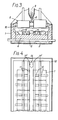
- the electrolytic cell illustrated in Figure 1 comprises a steel casing 1, lined with a layer of thermal and electrical insulation 2. It includes a conventional floor structure formed of carbon blocks 4 and transverse steel collector bars 5 at conventional intervals along the cell.
- the cell includes two rows of prebaked anodes 6.
- the shadow area of such anodes are indicated in dotted lines at 7 in Figure 2.
- the cell includes a crust breaker 8 arranged between the rows of anodes 6 for feeding alumina from a hopper 9 into the cell electrolyte 10.
- Barrier members 11 formed of alumina with a protective TiB 2 coating, are inset into the carbon floor blocks 4 and extend upwardly by a distance of 5 - 10 cms in the present instance.
- the barrier members 11 extend to the ends of the area lying in-the shadow of the anodes 6 but are of reduced height between the anode shadow area and the,end walls 12 of the cell. Between the barrier members 11 lying in the anode shadow a filling 14 of TiB 2 ceramic shapes or other ceramics resistant to attack by molten product metal and molten cell electrolyte are provided to act as a damper for lateral and longitudinal flow of molten metal in the cell in the area lying in the anode shadow.
- the product metal released at the cathode accumulates in the cell and is syphoned out at a well 15 at one end of the cell, the height of barrier members 11 being locally reduced at 11' to allow accumulation of metal in well 15 to take place.
- the difference in height between the top of the barrier members 11 and the top of the packed beds 14 is such that the metal level between successive tapping operations increases by approximately the same amount.
- the cell is preferably operated in such a way that the metal level falls to the level of the top of the packed bed after tapping so that the packed bed remains substantially completely submerged at all times.
- the metal level rises to approximately the top of the barrier members at the next tapping, but does not rise substantially above such barriers to avoid the presence of a substantial film of molten metal in which transverse horizontal currents might flow.
- non-conductive barrier members 11 substantially change the path of the cathode current, flowing from the electrolyte to the collector bars 5 by limiting the transverse current flow in the molten metal.
- non-conductive transverse barriers 16 are used in conjunction with longitudinal barriers in order to eliminate longitudinal horizontal currents and restrict the longitudinal sloshing motion of the metal.
- the transverse barriers are formed with very small notches or apertures (not shown) sized so as to permit produced metal to flow at a very slow rate to the well 15 with the result that longitudinal horizontal currents in the molten metal are held to a low value.
- carbon floor also includes a floor which has a surface layer of titanium diboride or other electrically conductive refractory material, resistant to attack by molten metal, and an underlying carbon layer, in contact with steel collector bars.
Landscapes
- Chemical & Material Sciences (AREA)
- Engineering & Computer Science (AREA)
- Chemical Kinetics & Catalysis (AREA)
- Electrochemistry (AREA)
- Materials Engineering (AREA)
- Metallurgy (AREA)
- Organic Chemistry (AREA)
- Electrolytic Production Of Metals (AREA)
- Secondary Cells (AREA)
- Battery Electrode And Active Subsutance (AREA)
- Electrolytic Production Of Non-Metals, Compounds, Apparatuses Therefor (AREA)
- Primary Cells (AREA)
- Electrodes For Compound Or Non-Metal Manufacture (AREA)
- Manufacture And Refinement Of Metals (AREA)
- Sealing Battery Cases Or Jackets (AREA)
- Photovoltaic Devices (AREA)
Priority Applications (1)
| Application Number | Priority Date | Filing Date | Title |
|---|---|---|---|
| AT82303227T ATE17134T1 (de) | 1981-06-25 | 1982-06-21 | Verbesserungen in elektrolytischen reduktionzellen. |
Applications Claiming Priority (2)
| Application Number | Priority Date | Filing Date | Title |
|---|---|---|---|
| GB8119588 | 1981-06-25 | ||
| GB8119588 | 1981-06-25 |
Publications (3)
| Publication Number | Publication Date |
|---|---|
| EP0068783A2 true EP0068783A2 (fr) | 1983-01-05 |
| EP0068783A3 EP0068783A3 (en) | 1983-04-06 |
| EP0068783B1 EP0068783B1 (fr) | 1985-12-27 |
Family
ID=10522791
Family Applications (1)
| Application Number | Title | Priority Date | Filing Date |
|---|---|---|---|
| EP82303227A Expired EP0068783B1 (fr) | 1981-06-25 | 1982-06-21 | Améliorations dans les cellules de réduction électrolytique |
Country Status (12)
| Country | Link |
|---|---|
| US (1) | US4495047A (fr) |
| EP (1) | EP0068783B1 (fr) |
| JP (1) | JPS6033904B2 (fr) |
| KR (1) | KR880000706B1 (fr) |
| AT (1) | ATE17134T1 (fr) |
| AU (1) | AU555468B2 (fr) |
| BR (1) | BR8203697A (fr) |
| CA (1) | CA1186281A (fr) |
| DE (1) | DE3268105D1 (fr) |
| ES (1) | ES8305846A1 (fr) |
| NO (1) | NO158108C (fr) |
| ZA (1) | ZA824254B (fr) |
Cited By (1)
| Publication number | Priority date | Publication date | Assignee | Title |
|---|---|---|---|---|
| EP0069501B1 (fr) * | 1981-06-25 | 1985-12-27 | Alcan International Limited | Améliorations dans les cellules de réduction électrolytique |
Families Citing this family (4)
| Publication number | Priority date | Publication date | Assignee | Title |
|---|---|---|---|---|
| US5167787A (en) * | 1987-07-14 | 1992-12-01 | Alcan International Limited | Linings for aluminum reduction cells |
| CN101649470B (zh) * | 2008-08-12 | 2013-09-11 | 高德金 | 带有铝液磁旋流调整装置的铝电解槽阴极内衬 |
| WO2015123502A1 (fr) | 2014-02-13 | 2015-08-20 | Phinix, LLC | Raffinage électrolytique de magnésium à partir de déchets métalliques d'alliages d'aluminium ou de magnésium |
| AU2015315310B2 (en) | 2014-09-10 | 2020-10-22 | Alcoa Usa Corp. | Systems and methods of protecting electrolysis cell sidewalls |
Family Cites Families (14)
| Publication number | Priority date | Publication date | Assignee | Title |
|---|---|---|---|---|
| US4297180A (en) * | 1976-08-25 | 1981-10-27 | Aluminum Company Of America | Electrolytic production of metal |
| CH635132A5 (de) * | 1978-07-04 | 1983-03-15 | Alusuisse | Kathode fuer einen schmelzflusselektrolyseofen. |
| US4338177A (en) * | 1978-09-22 | 1982-07-06 | Metallurgical, Inc. | Electrolytic cell for the production of aluminum |
| US4177128A (en) * | 1978-12-20 | 1979-12-04 | Ppg Industries, Inc. | Cathode element for use in aluminum reduction cell |
| US4231853A (en) * | 1979-04-27 | 1980-11-04 | Ppg Industries, Inc. | Cathodic current conducting elements for use in aluminum reduction cells |
| CH643600A5 (de) * | 1979-12-05 | 1984-06-15 | Alusuisse | Elektrolysezelle zur herstellung von aluminium. |
| CH644406A5 (de) * | 1980-04-03 | 1984-07-31 | Alusuisse | Schmelzflusselektrolysezelle zur herstellung von aluminium. |
| CH643885A5 (de) * | 1980-05-14 | 1984-06-29 | Alusuisse | Elektrodenanordnung einer schmelzflusselektrolysezelle zur herstellung von aluminium. |
| AU543106B2 (en) * | 1980-05-23 | 1985-04-04 | Swiss Aluminium Ltd. | Cathod for aluminium production |
| US4410403A (en) * | 1980-06-17 | 1983-10-18 | Aluminum Company Of America | Electrolysis method |
| US4349427A (en) * | 1980-06-23 | 1982-09-14 | Kaiser Aluminum & Chemical Corporation | Aluminum reduction cell electrode |
| US4308114A (en) * | 1980-07-21 | 1981-12-29 | Aluminum Company Of America | Electrolytic production of aluminum using a composite cathode |
| US4308115A (en) * | 1980-08-15 | 1981-12-29 | Aluminum Company Of America | Method of producing aluminum using graphite cathode coated with refractory hard metal |
| US4383910A (en) * | 1981-05-21 | 1983-05-17 | Reynolds Metals Company | Alumina reduction cell |
-
1982
- 1982-06-16 ZA ZA824254A patent/ZA824254B/xx unknown
- 1982-06-21 EP EP82303227A patent/EP0068783B1/fr not_active Expired
- 1982-06-21 DE DE8282303227T patent/DE3268105D1/de not_active Expired
- 1982-06-21 AT AT82303227T patent/ATE17134T1/de not_active IP Right Cessation
- 1982-06-23 US US06/391,405 patent/US4495047A/en not_active Expired - Fee Related
- 1982-06-24 BR BR8203697A patent/BR8203697A/pt unknown
- 1982-06-24 KR KR8202823A patent/KR880000706B1/ko not_active Expired
- 1982-06-24 AU AU85302/82A patent/AU555468B2/en not_active Ceased
- 1982-06-25 ES ES513433A patent/ES8305846A1/es not_active Expired
- 1982-06-25 JP JP57109689A patent/JPS6033904B2/ja not_active Expired
- 1982-06-25 CA CA000406055A patent/CA1186281A/fr not_active Expired
- 1982-06-25 NO NO822173A patent/NO158108C/no unknown
Cited By (1)
| Publication number | Priority date | Publication date | Assignee | Title |
|---|---|---|---|---|
| EP0069501B1 (fr) * | 1981-06-25 | 1985-12-27 | Alcan International Limited | Améliorations dans les cellules de réduction électrolytique |
Also Published As
| Publication number | Publication date |
|---|---|
| JPS586990A (ja) | 1983-01-14 |
| AU8530282A (en) | 1983-01-06 |
| EP0068783B1 (fr) | 1985-12-27 |
| JPS6033904B2 (ja) | 1985-08-06 |
| ATE17134T1 (de) | 1986-01-15 |
| CA1186281A (fr) | 1985-04-30 |
| KR880000706B1 (ko) | 1988-04-25 |
| ES513433A0 (es) | 1983-04-16 |
| NO822173L (no) | 1982-12-27 |
| EP0068783A3 (en) | 1983-04-06 |
| NO158108B (no) | 1988-04-05 |
| BR8203697A (pt) | 1983-06-21 |
| NO158108C (no) | 1988-07-13 |
| KR840000674A (ko) | 1984-02-25 |
| ZA824254B (en) | 1983-05-25 |
| AU555468B2 (en) | 1986-09-25 |
| US4495047A (en) | 1985-01-22 |
| DE3268105D1 (en) | 1986-02-06 |
| ES8305846A1 (es) | 1983-04-16 |
Similar Documents
| Publication | Publication Date | Title |
|---|---|---|
| EP0027016B1 (fr) | Appareillage pour la production électrolytique de magnésium métallique à partir de son chlorure | |
| WO2011148347A1 (fr) | Conception de cathode de cellule hall-héroult | |
| CA1164823A (fr) | Agencement d'electrodes dans une pile de fabrication de l'aluminium a partir de sels en fusion | |
| EP0069502B1 (fr) | Améliorations dans les cellules de réduction électrolytique | |
| CA1114328A (fr) | Methode et dispositif de production d'aluminium par electrolyse d'une charge en fusion | |
| EP2066831B1 (fr) | Cellule d'électrolyse et procédé de fonctionnement de ladite cellule | |
| CA1178241A (fr) | Groupement de barres omnibus pour cellules de reduction electrolytiques | |
| US4495047A (en) | Electrolytic reduction cells | |
| EP0308013B1 (fr) | Fond de cuve composite pour l'obtention électrolytique de l'aluminium | |
| US4613414A (en) | Method for magnesium production | |
| CH644406A5 (de) | Schmelzflusselektrolysezelle zur herstellung von aluminium. | |
| US4505796A (en) | Electrolytic reduction cells | |
| US3322658A (en) | Aluminum electrolytic cell and method of use | |
| GB1596449A (en) | Method for extracting heat from chamber containing molten salt | |
| CA1152444A (fr) | Dispositif et methode de production de l'aluminium | |
| US4462885A (en) | Conductor arrangement of electrolytic cells for producing aluminum | |
| WO2009033260A1 (fr) | Régulation de courant de dérivation dans des cellules d'électrolyse de métal léger multipolaires | |
| US3369986A (en) | Cathode connection for a reduction cell | |
| FI70731B (fi) | Anordning foer framstaellning av ickejaern-metaller medelst elktrolys | |
| DE3022232A1 (de) | Elektrodenanordnung einer schmelzflusselektrolysezelle zur herstellung von aluminium |
Legal Events
| Date | Code | Title | Description |
|---|---|---|---|
| PUAI | Public reference made under article 153(3) epc to a published international application that has entered the european phase |
Free format text: ORIGINAL CODE: 0009012 |
|
| AK | Designated contracting states |
Designated state(s): AT CH DE FR GB IT LI NL SE |
|
| PUAL | Search report despatched |
Free format text: ORIGINAL CODE: 0009013 |
|
| AK | Designated contracting states |
Designated state(s): AT CH DE FR GB IT LI NL SE |
|
| 17P | Request for examination filed |
Effective date: 19830707 |
|
| RAP1 | Party data changed (applicant data changed or rights of an application transferred) |
Owner name: ALCAN INTERNATIONAL LIMITED |
|
| RAP1 | Party data changed (applicant data changed or rights of an application transferred) |
Owner name: ALCAN INTERNATIONAL LIMITED |
|
| ITF | It: translation for a ep patent filed | ||
| GRAA | (expected) grant |
Free format text: ORIGINAL CODE: 0009210 |
|
| AK | Designated contracting states |
Designated state(s): AT CH DE FR GB IT LI NL SE |
|
| PG25 | Lapsed in a contracting state [announced via postgrant information from national office to epo] |
Ref country code: AT Effective date: 19851227 |
|
| REF | Corresponds to: |
Ref document number: 17134 Country of ref document: AT Date of ref document: 19860115 Kind code of ref document: T |
|
| PG25 | Lapsed in a contracting state [announced via postgrant information from national office to epo] |
Ref country code: SE Effective date: 19860131 |
|
| REF | Corresponds to: |
Ref document number: 3268105 Country of ref document: DE Date of ref document: 19860206 |
|
| ET | Fr: translation filed | ||
| PLBE | No opposition filed within time limit |
Free format text: ORIGINAL CODE: 0009261 |
|
| STAA | Information on the status of an ep patent application or granted ep patent |
Free format text: STATUS: NO OPPOSITION FILED WITHIN TIME LIMIT |
|
| 26N | No opposition filed | ||
| ITTA | It: last paid annual fee | ||
| PGFP | Annual fee paid to national office [announced via postgrant information from national office to epo] |
Ref country code: FR Payment date: 19900517 Year of fee payment: 9 |
|
| PGFP | Annual fee paid to national office [announced via postgrant information from national office to epo] |
Ref country code: DE Payment date: 19900521 Year of fee payment: 9 Ref country code: CH Payment date: 19900521 Year of fee payment: 9 |
|
| PGFP | Annual fee paid to national office [announced via postgrant information from national office to epo] |
Ref country code: GB Payment date: 19900601 Year of fee payment: 9 |
|
| PGFP | Annual fee paid to national office [announced via postgrant information from national office to epo] |
Ref country code: NL Payment date: 19900630 Year of fee payment: 9 |
|
| PG25 | Lapsed in a contracting state [announced via postgrant information from national office to epo] |
Ref country code: GB Effective date: 19910621 |
|
| PG25 | Lapsed in a contracting state [announced via postgrant information from national office to epo] |
Ref country code: LI Effective date: 19910630 Ref country code: CH Effective date: 19910630 |
|
| PG25 | Lapsed in a contracting state [announced via postgrant information from national office to epo] |
Ref country code: NL Effective date: 19920101 |
|
| NLV4 | Nl: lapsed or anulled due to non-payment of the annual fee | ||
| GBPC | Gb: european patent ceased through non-payment of renewal fee | ||
| PG25 | Lapsed in a contracting state [announced via postgrant information from national office to epo] |
Ref country code: FR Effective date: 19920228 |
|
| REG | Reference to a national code |
Ref country code: CH Ref legal event code: PL |
|
| PG25 | Lapsed in a contracting state [announced via postgrant information from national office to epo] |
Ref country code: DE Effective date: 19920401 |
|
| REG | Reference to a national code |
Ref country code: FR Ref legal event code: ST |