EP0068836A1 - Soupape de sécurité non-réobturable pour cellules électrochimiques - Google Patents
Soupape de sécurité non-réobturable pour cellules électrochimiques Download PDFInfo
- Publication number
- EP0068836A1 EP0068836A1 EP82303316A EP82303316A EP0068836A1 EP 0068836 A1 EP0068836 A1 EP 0068836A1 EP 82303316 A EP82303316 A EP 82303316A EP 82303316 A EP82303316 A EP 82303316A EP 0068836 A1 EP0068836 A1 EP 0068836A1
- Authority
- EP
- European Patent Office
- Prior art keywords
- cell
- secured
- housing
- container
- vent orifice
- Prior art date
- Legal status (The legal status is an assumption and is not a legal conclusion. Google has not performed a legal analysis and makes no representation as to the accuracy of the status listed.)
- Ceased
Links
- 239000012530 fluid Substances 0.000 claims abstract description 4
- 239000007788 liquid Substances 0.000 claims description 22
- 239000000463 material Substances 0.000 description 13
- 150000003839 salts Chemical class 0.000 description 12
- FYSNRJHAOHDILO-UHFFFAOYSA-N thionyl chloride Chemical compound ClS(Cl)=O FYSNRJHAOHDILO-UHFFFAOYSA-N 0.000 description 12
- 229910052744 lithium Inorganic materials 0.000 description 11
- 239000010406 cathode material Substances 0.000 description 9
- 230000000737 periodic effect Effects 0.000 description 8
- 229910052708 sodium Inorganic materials 0.000 description 8
- 239000011734 sodium Substances 0.000 description 8
- 239000007789 gas Substances 0.000 description 7
- 239000002904 solvent Substances 0.000 description 7
- 239000010935 stainless steel Substances 0.000 description 7
- 229910001220 stainless steel Inorganic materials 0.000 description 7
- -1 vanadyl tribromide Chemical compound 0.000 description 7
- PXHVJJICTQNCMI-UHFFFAOYSA-N Nickel Chemical compound [Ni] PXHVJJICTQNCMI-UHFFFAOYSA-N 0.000 description 6
- 150000004820 halides Chemical class 0.000 description 6
- XHXFXVLFKHQFAL-UHFFFAOYSA-N phosphoryl trichloride Chemical compound ClP(Cl)(Cl)=O XHXFXVLFKHQFAL-UHFFFAOYSA-N 0.000 description 6
- 239000002841 Lewis acid Substances 0.000 description 5
- WHXSMMKQMYFTQS-UHFFFAOYSA-N Lithium Chemical compound [Li] WHXSMMKQMYFTQS-UHFFFAOYSA-N 0.000 description 5
- 239000011230 binding agent Substances 0.000 description 5
- 150000007517 lewis acids Chemical class 0.000 description 5
- 239000000243 solution Substances 0.000 description 5
- YBBRCQOCSYXUOC-UHFFFAOYSA-N sulfuryl dichloride Chemical compound ClS(Cl)(=O)=O YBBRCQOCSYXUOC-UHFFFAOYSA-N 0.000 description 5
- RAHZWNYVWXNFOC-UHFFFAOYSA-N Sulphur dioxide Chemical compound O=S=O RAHZWNYVWXNFOC-UHFFFAOYSA-N 0.000 description 4
- VSCWAEJMTAWNJL-UHFFFAOYSA-K aluminium trichloride Chemical compound Cl[Al](Cl)Cl VSCWAEJMTAWNJL-UHFFFAOYSA-K 0.000 description 4
- 239000003792 electrolyte Substances 0.000 description 4
- KWGKDLIKAYFUFQ-UHFFFAOYSA-M lithium chloride Chemical compound [Li+].[Cl-] KWGKDLIKAYFUFQ-UHFFFAOYSA-M 0.000 description 4
- 229910052751 metal Inorganic materials 0.000 description 4
- 239000002184 metal Substances 0.000 description 4
- 150000002739 metals Chemical class 0.000 description 4
- 239000000126 substance Substances 0.000 description 4
- 238000013022 venting Methods 0.000 description 4
- OKTJSMMVPCPJKN-UHFFFAOYSA-N Carbon Chemical compound [C] OKTJSMMVPCPJKN-UHFFFAOYSA-N 0.000 description 3
- 239000002253 acid Substances 0.000 description 3
- BZRNNFDADQGMGA-UHFFFAOYSA-N ctk5d9411 Chemical compound Br[S] BZRNNFDADQGMGA-UHFFFAOYSA-N 0.000 description 3
- PXJJSXABGXMUSU-UHFFFAOYSA-N disulfur dichloride Chemical compound ClSSCl PXJJSXABGXMUSU-UHFFFAOYSA-N 0.000 description 3
- 229910052759 nickel Inorganic materials 0.000 description 3
- 230000002093 peripheral effect Effects 0.000 description 3
- 238000007789 sealing Methods 0.000 description 3
- PMOBWAXBGUSOPS-UHFFFAOYSA-N selenium tetrafluoride Chemical compound F[Se](F)(F)F PMOBWAXBGUSOPS-UHFFFAOYSA-N 0.000 description 3
- 238000003466 welding Methods 0.000 description 3
- YEJRWHAVMIAJKC-UHFFFAOYSA-N 4-Butyrolactone Chemical compound O=C1CCCO1 YEJRWHAVMIAJKC-UHFFFAOYSA-N 0.000 description 2
- SGDKTJPVCKQTHK-UHFFFAOYSA-N 5-bromo-2-fluoro-3-nitropyridine Chemical compound [O-][N+](=O)C1=CC(Br)=CN=C1F SGDKTJPVCKQTHK-UHFFFAOYSA-N 0.000 description 2
- KLZUFWVZNOTSEM-UHFFFAOYSA-K Aluminium flouride Chemical compound F[Al](F)F KLZUFWVZNOTSEM-UHFFFAOYSA-K 0.000 description 2
- DGAQECJNVWCQMB-PUAWFVPOSA-M Ilexoside XXIX Chemical compound C[C@@H]1CC[C@@]2(CC[C@@]3(C(=CC[C@H]4[C@]3(CC[C@@H]5[C@@]4(CC[C@@H](C5(C)C)OS(=O)(=O)[O-])C)C)[C@@H]2[C@]1(C)O)C)C(=O)O[C@H]6[C@@H]([C@H]([C@@H]([C@H](O6)CO)O)O)O.[Na+] DGAQECJNVWCQMB-PUAWFVPOSA-M 0.000 description 2
- XEEYBQQBJWHFJM-UHFFFAOYSA-N Iron Chemical compound [Fe] XEEYBQQBJWHFJM-UHFFFAOYSA-N 0.000 description 2
- WCUXLLCKKVVCTQ-UHFFFAOYSA-M Potassium chloride Chemical compound [Cl-].[K+] WCUXLLCKKVVCTQ-UHFFFAOYSA-M 0.000 description 2
- FAPWRFPIFSIZLT-UHFFFAOYSA-M Sodium chloride Chemical compound [Na+].[Cl-] FAPWRFPIFSIZLT-UHFFFAOYSA-M 0.000 description 2
- WYURNTSHIVDZCO-UHFFFAOYSA-N Tetrahydrofuran Chemical compound C1CCOC1 WYURNTSHIVDZCO-UHFFFAOYSA-N 0.000 description 2
- JIAARYAFYJHUJI-UHFFFAOYSA-L Zinc chloride Inorganic materials [Cl-].[Cl-].[Zn+2] JIAARYAFYJHUJI-UHFFFAOYSA-L 0.000 description 2
- 150000007513 acids Chemical class 0.000 description 2
- 229910052783 alkali metal Inorganic materials 0.000 description 2
- 150000001340 alkali metals Chemical class 0.000 description 2
- 150000001342 alkaline earth metals Chemical class 0.000 description 2
- PQLAYKMGZDUDLQ-UHFFFAOYSA-K aluminium bromide Chemical compound Br[Al](Br)Br PQLAYKMGZDUDLQ-UHFFFAOYSA-K 0.000 description 2
- 239000010405 anode material Substances 0.000 description 2
- YXWZBDDFTDHQGT-UHFFFAOYSA-J bromo(trichloro)stannane Chemical compound [Cl-].[Cl-].[Cl-].[Br-].[Sn+4] YXWZBDDFTDHQGT-UHFFFAOYSA-J 0.000 description 2
- XXFBOXZYQLMDQA-UHFFFAOYSA-N bromoselanyl selenohypobromite Chemical compound Br[Se][Se]Br XXFBOXZYQLMDQA-UHFFFAOYSA-N 0.000 description 2
- 229910052799 carbon Inorganic materials 0.000 description 2
- AHXGRMIPHCAXFP-UHFFFAOYSA-L chromyl dichloride Chemical compound Cl[Cr](Cl)(=O)=O AHXGRMIPHCAXFP-UHFFFAOYSA-L 0.000 description 2
- HOBKJDRIWYGNQZ-UHFFFAOYSA-J dibromo(dichloro)stannane Chemical compound Cl[Sn](Cl)(Br)Br HOBKJDRIWYGNQZ-UHFFFAOYSA-J 0.000 description 2
- BPFZRKQDXVZTFD-UHFFFAOYSA-N disulfur decafluoride Chemical compound FS(F)(F)(F)(F)S(F)(F)(F)(F)F BPFZRKQDXVZTFD-UHFFFAOYSA-N 0.000 description 2
- 239000003365 glass fiber Substances 0.000 description 2
- AMXOYNBUYSYVKV-UHFFFAOYSA-M lithium bromide Chemical compound [Li+].[Br-] AMXOYNBUYSYVKV-UHFFFAOYSA-M 0.000 description 2
- PQXKHYXIUOZZFA-UHFFFAOYSA-M lithium fluoride Chemical compound [Li+].[F-] PQXKHYXIUOZZFA-UHFFFAOYSA-M 0.000 description 2
- 238000000034 method Methods 0.000 description 2
- 239000000203 mixture Substances 0.000 description 2
- LQNUZADURLCDLV-UHFFFAOYSA-N nitrobenzene Chemical compound [O-][N+](=O)C1=CC=CC=C1 LQNUZADURLCDLV-UHFFFAOYSA-N 0.000 description 2
- NFVUDQKTAWONMJ-UHFFFAOYSA-I pentafluorovanadium Chemical compound [F-].[F-].[F-].[F-].[F-].[V+5] NFVUDQKTAWONMJ-UHFFFAOYSA-I 0.000 description 2
- IOLCXVTUBQKXJR-UHFFFAOYSA-M potassium bromide Chemical compound [K+].[Br-] IOLCXVTUBQKXJR-UHFFFAOYSA-M 0.000 description 2
- NROKBHXJSPEDAR-UHFFFAOYSA-M potassium fluoride Chemical compound [F-].[K+] NROKBHXJSPEDAR-UHFFFAOYSA-M 0.000 description 2
- JHJLBTNAGRQEKS-UHFFFAOYSA-M sodium bromide Chemical compound [Na+].[Br-] JHJLBTNAGRQEKS-UHFFFAOYSA-M 0.000 description 2
- PUZPDOWCWNUUKD-UHFFFAOYSA-M sodium fluoride Chemical compound [F-].[Na+] PUZPDOWCWNUUKD-UHFFFAOYSA-M 0.000 description 2
- PJYXVICYYHGLSW-UHFFFAOYSA-J tetrachloroplumbane Chemical compound Cl[Pb](Cl)(Cl)Cl PJYXVICYYHGLSW-UHFFFAOYSA-J 0.000 description 2
- HFRXJVQOXRXOPP-UHFFFAOYSA-N thionyl bromide Chemical compound BrS(Br)=O HFRXJVQOXRXOPP-UHFFFAOYSA-N 0.000 description 2
- WQYSXVGEZYESBR-UHFFFAOYSA-N thiophosphoryl chloride Chemical compound ClP(Cl)(Cl)=S WQYSXVGEZYESBR-UHFFFAOYSA-N 0.000 description 2
- XJDNKRIXUMDJCW-UHFFFAOYSA-J titanium tetrachloride Chemical compound Cl[Ti](Cl)(Cl)Cl XJDNKRIXUMDJCW-UHFFFAOYSA-J 0.000 description 2
- AHCHEGZCJVSHOL-UHFFFAOYSA-J tribromo(chloro)stannane Chemical compound Cl[Sn](Br)(Br)Br AHCHEGZCJVSHOL-UHFFFAOYSA-J 0.000 description 2
- OWNZHTHZRZVKSQ-UHFFFAOYSA-N tribromo(sulfanylidene)-$l^{5}-phosphane Chemical compound BrP(Br)(Br)=S OWNZHTHZRZVKSQ-UHFFFAOYSA-N 0.000 description 2
- 229920002554 vinyl polymer Polymers 0.000 description 2
- KPZGRMZPZLOPBS-UHFFFAOYSA-N 1,3-dichloro-2,2-bis(chloromethyl)propane Chemical compound ClCC(CCl)(CCl)CCl KPZGRMZPZLOPBS-UHFFFAOYSA-N 0.000 description 1
- WNXJIVFYUVYPPR-UHFFFAOYSA-N 1,3-dioxolane Chemical compound C1COCO1 WNXJIVFYUVYPPR-UHFFFAOYSA-N 0.000 description 1
- FZKPQHFEMFIDNR-UHFFFAOYSA-N 2-hydroxyethyl hydrogen sulfite Chemical compound OCCOS(O)=O FZKPQHFEMFIDNR-UHFFFAOYSA-N 0.000 description 1
- AKUSZFPCJFNRSZ-UHFFFAOYSA-N 3,4-dimethyl-1,2-oxazole Chemical compound CC1=CON=C1C AKUSZFPCJFNRSZ-UHFFFAOYSA-N 0.000 description 1
- VWIIJDNADIEEDB-UHFFFAOYSA-N 3-methyl-1,3-oxazolidin-2-one Chemical compound CN1CCOC1=O VWIIJDNADIEEDB-UHFFFAOYSA-N 0.000 description 1
- 229910015900 BF3 Inorganic materials 0.000 description 1
- OIFBSDVPJOWBCH-UHFFFAOYSA-N Diethyl carbonate Chemical compound CCOC(=O)OCC OIFBSDVPJOWBCH-UHFFFAOYSA-N 0.000 description 1
- XTHFKEDIFFGKHM-UHFFFAOYSA-N Dimethoxyethane Chemical compound COCCOC XTHFKEDIFFGKHM-UHFFFAOYSA-N 0.000 description 1
- UFHFLCQGNIYNRP-UHFFFAOYSA-N Hydrogen Chemical compound [H][H] UFHFLCQGNIYNRP-UHFFFAOYSA-N 0.000 description 1
- 239000004698 Polyethylene Substances 0.000 description 1
- 239000004743 Polypropylene Substances 0.000 description 1
- 239000004793 Polystyrene Substances 0.000 description 1
- ZLMJMSJWJFRBEC-UHFFFAOYSA-N Potassium Chemical compound [K] ZLMJMSJWJFRBEC-UHFFFAOYSA-N 0.000 description 1
- JFBZPFYRPYOZCQ-UHFFFAOYSA-N [Li].[Al] Chemical compound [Li].[Al] JFBZPFYRPYOZCQ-UHFFFAOYSA-N 0.000 description 1
- 239000000370 acceptor Substances 0.000 description 1
- 239000006230 acetylene black Substances 0.000 description 1
- 229920006397 acrylic thermoplastic Polymers 0.000 description 1
- 230000004913 activation Effects 0.000 description 1
- 238000004026 adhesive bonding Methods 0.000 description 1
- 229910000573 alkali metal alloy Inorganic materials 0.000 description 1
- 229910052784 alkaline earth metal Inorganic materials 0.000 description 1
- 229910000941 alkaline earth metal alloy Inorganic materials 0.000 description 1
- 229910045601 alloy Inorganic materials 0.000 description 1
- 239000000956 alloy Substances 0.000 description 1
- VMPVEPPRYRXYNP-UHFFFAOYSA-I antimony(5+);pentachloride Chemical compound Cl[Sb](Cl)(Cl)(Cl)Cl VMPVEPPRYRXYNP-UHFFFAOYSA-I 0.000 description 1
- 239000002585 base Substances 0.000 description 1
- PASDCCFISLVPSO-UHFFFAOYSA-N benzoyl chloride Chemical compound ClC(=O)C1=CC=CC=C1 PASDCCFISLVPSO-UHFFFAOYSA-N 0.000 description 1
- ILAHWRKJUDSMFH-UHFFFAOYSA-N boron tribromide Chemical compound BrB(Br)Br ILAHWRKJUDSMFH-UHFFFAOYSA-N 0.000 description 1
- WTEOIRVLGSZEPR-UHFFFAOYSA-N boron trifluoride Chemical compound FB(F)F WTEOIRVLGSZEPR-UHFFFAOYSA-N 0.000 description 1
- 239000003575 carbonaceous material Substances 0.000 description 1
- 239000006182 cathode active material Substances 0.000 description 1
- 239000007795 chemical reaction product Substances 0.000 description 1
- 238000010276 construction Methods 0.000 description 1
- 238000007796 conventional method Methods 0.000 description 1
- 239000006184 cosolvent Substances 0.000 description 1
- 238000005336 cracking Methods 0.000 description 1
- 230000003247 decreasing effect Effects 0.000 description 1
- BDUPRNVPXOHWIL-UHFFFAOYSA-N dimethyl sulfite Chemical compound COS(=O)OC BDUPRNVPXOHWIL-UHFFFAOYSA-N 0.000 description 1
- 239000011521 glass Substances 0.000 description 1
- 229910052739 hydrogen Inorganic materials 0.000 description 1
- 239000001257 hydrogen Substances 0.000 description 1
- 238000011065 in-situ storage Methods 0.000 description 1
- 229910000765 intermetallic Inorganic materials 0.000 description 1
- 150000002500 ions Chemical class 0.000 description 1
- 229910052742 iron Inorganic materials 0.000 description 1
- GCICAPWZNUIIDV-UHFFFAOYSA-N lithium magnesium Chemical compound [Li].[Mg] GCICAPWZNUIIDV-UHFFFAOYSA-N 0.000 description 1
- GLNWILHOFOBOFD-UHFFFAOYSA-N lithium sulfide Chemical compound [Li+].[Li+].[S-2] GLNWILHOFOBOFD-UHFFFAOYSA-N 0.000 description 1
- LWRYTNDOEJYQME-UHFFFAOYSA-N lithium;sulfanylideneiron Chemical compound [Li].[Fe]=S LWRYTNDOEJYQME-UHFFFAOYSA-N 0.000 description 1
- 238000004519 manufacturing process Methods 0.000 description 1
- 239000012528 membrane Substances 0.000 description 1
- 239000011236 particulate material Substances 0.000 description 1
- UHZYTMXLRWXGPK-UHFFFAOYSA-N phosphorus pentachloride Chemical compound ClP(Cl)(Cl)(Cl)Cl UHZYTMXLRWXGPK-UHFFFAOYSA-N 0.000 description 1
- 239000004033 plastic Substances 0.000 description 1
- 229920003023 plastic Polymers 0.000 description 1
- 239000004014 plasticizer Substances 0.000 description 1
- 229920003229 poly(methyl methacrylate) Polymers 0.000 description 1
- 229920000573 polyethylene Polymers 0.000 description 1
- 229920001155 polypropylene Polymers 0.000 description 1
- 229920002223 polystyrene Polymers 0.000 description 1
- 229910052700 potassium Inorganic materials 0.000 description 1
- 239000011591 potassium Substances 0.000 description 1
- 239000001103 potassium chloride Substances 0.000 description 1
- 235000011164 potassium chloride Nutrition 0.000 description 1
- 235000003270 potassium fluoride Nutrition 0.000 description 1
- 239000011698 potassium fluoride Substances 0.000 description 1
- 230000002028 premature Effects 0.000 description 1
- RUOJZAUFBMNUDX-UHFFFAOYSA-N propylene carbonate Chemical compound CC1COC(=O)O1 RUOJZAUFBMNUDX-UHFFFAOYSA-N 0.000 description 1
- 239000011347 resin Substances 0.000 description 1
- 229920005989 resin Polymers 0.000 description 1
- 238000010008 shearing Methods 0.000 description 1
- 239000011780 sodium chloride Substances 0.000 description 1
- 235000013024 sodium fluoride Nutrition 0.000 description 1
- 239000011775 sodium fluoride Substances 0.000 description 1
- 239000006104 solid solution Substances 0.000 description 1
- 239000003381 stabilizer Substances 0.000 description 1
- 238000003860 storage Methods 0.000 description 1
- HXJUTPCZVOIRIF-UHFFFAOYSA-N sulfolane Chemical compound O=S1(=O)CCCC1 HXJUTPCZVOIRIF-UHFFFAOYSA-N 0.000 description 1
- ISXSCDLOGDJUNJ-UHFFFAOYSA-N tert-butyl prop-2-enoate Chemical compound CC(C)(C)OC(=O)C=C ISXSCDLOGDJUNJ-UHFFFAOYSA-N 0.000 description 1
- YLQBMQCUIZJEEH-UHFFFAOYSA-N tetrahydrofuran Natural products C=1C=COC=1 YLQBMQCUIZJEEH-UHFFFAOYSA-N 0.000 description 1
- FAQYAMRNWDIXMY-UHFFFAOYSA-N trichloroborane Chemical compound ClB(Cl)Cl FAQYAMRNWDIXMY-UHFFFAOYSA-N 0.000 description 1
- 125000000391 vinyl group Chemical group [H]C([*])=C([H])[H] 0.000 description 1
- 235000005074 zinc chloride Nutrition 0.000 description 1
- 239000011592 zinc chloride Substances 0.000 description 1
- DUNKXUFBGCUVQW-UHFFFAOYSA-J zirconium tetrachloride Chemical compound Cl[Zr](Cl)(Cl)Cl DUNKXUFBGCUVQW-UHFFFAOYSA-J 0.000 description 1
Images
Classifications
-
- H—ELECTRICITY
- H01—ELECTRIC ELEMENTS
- H01G—CAPACITORS; CAPACITORS, RECTIFIERS, DETECTORS, SWITCHING DEVICES, LIGHT-SENSITIVE OR TEMPERATURE-SENSITIVE DEVICES OF THE ELECTROLYTIC TYPE
- H01G9/00—Electrolytic capacitors, rectifiers, detectors, switching devices, light-sensitive or temperature-sensitive devices; Processes of their manufacture
- H01G9/004—Details
- H01G9/08—Housing; Encapsulation
- H01G9/12—Vents or other means allowing expansion
-
- H—ELECTRICITY
- H01—ELECTRIC ELEMENTS
- H01M—PROCESSES OR MEANS, e.g. BATTERIES, FOR THE DIRECT CONVERSION OF CHEMICAL ENERGY INTO ELECTRICAL ENERGY
- H01M50/00—Constructional details or processes of manufacture of the non-active parts of electrochemical cells other than fuel cells, e.g. hybrid cells
- H01M50/30—Arrangements for facilitating escape of gases
- H01M50/342—Non-re-sealable arrangements
-
- Y—GENERAL TAGGING OF NEW TECHNOLOGICAL DEVELOPMENTS; GENERAL TAGGING OF CROSS-SECTIONAL TECHNOLOGIES SPANNING OVER SEVERAL SECTIONS OF THE IPC; TECHNICAL SUBJECTS COVERED BY FORMER USPC CROSS-REFERENCE ART COLLECTIONS [XRACs] AND DIGESTS
- Y02—TECHNOLOGIES OR APPLICATIONS FOR MITIGATION OR ADAPTATION AGAINST CLIMATE CHANGE
- Y02E—REDUCTION OF GREENHOUSE GAS [GHG] EMISSIONS, RELATED TO ENERGY GENERATION, TRANSMISSION OR DISTRIBUTION
- Y02E60/00—Enabling technologies; Technologies with a potential or indirect contribution to GHG emissions mitigation
- Y02E60/10—Energy storage using batteries
Definitions
- This invention relates to a non-resealable safety vent for galvanic cells, such as non-aqueous cells, which comprises the employment of a flexible sheet disposed over an orifice in the housing of the cell and secured proximal its peripheral edge to the housing of the cell and having a selected area of the flexible sheet that is spaced from the orifice secured to the housing of the cell, for example by a spot weld.
- fluid (gas or liquid) pressure transmitted through the orifice will exert force against the flexible sheet where it will be substantially concentrated about said secured small area until a predetermined force level is reached that will tear the sheet about the secured small area, producing a permanent vent in the cell.
- Galvanic cells may generate large quantities of gas under certain conditions during use. Since many such cells are required to be tightly sealed in order to prevent loss of electrolyte by leakage, high internal gas pressure may develop. Such pressure may cause leakage, bulging or possible rupture of the container of the cell under abusive conditions, if not properly vented.
- a non-aqueous electrochemical cell comprising an anode, a cathode collector and a cathode-electrolyte, said cathode-electrolyte comprising a solution of an ionically conductive solute dissolved in an active cathode depolarizer wherein said active cathode depolarizer comprises a liquid oxyhalide of an element of Group V or Group VI of th-e Periodic Table.
- the "Periodic Table” is the Periodic Table of Elements as set forth on the inside back cover of the Handbook of Chemistry and Physics, 48th Edition, The Chemical Rubber Company Cleveland, Ohio, 1967-1968.
- non-aqueous cathode materials examples include sulfuryl chloride, thionyl chloride, phosphorus oxychloride, thionyl bromide, chromyl chloride, vanadyl tribromide and selenium oxychloride.
- liquid cathode materials would be the halides of an element of Group IV to Group VI of the Periodic Table.
- non-aqueous cathode materials are sulfur monochloride, sulfur monobromide, selenium tetrafluoride, selenium monobromide, thiophosphoryl chloride, thiophosphoryl bromide, vanadium pentafluoride, lead tetrachloride, titanium tetrachloride, disulfur decafluoride, tin bromide trichloride, tin dibromide dichloride and tin tribromide chloride.
- oxyhalide and halide liquid cathode non-aqueous cells may be possible that during storage or use, some of the oxyhalide, halide or their reaction products may escape from the cell. This escape of liquids and/or gases could cause damage to the device employing the cell or to the surface of a compartment or shelf where the cell is stored.
- the seal of the cell is effectively permanently secured, then it is possible that the buildup to internal pressure within the cell could cause the container of the cell to rupture. To prevent rupture of the container of the cell from possible internal pressure buildup, it is thus necessary to vent the cell at some predetermined pressure. It has been reported that some oxyhalides such as thionyl chloride and sulfuryl chloride should be vented at pressures below about 500 psi and preferably between about 150 and 300 psi.
- a safety non-resealable vent closure for electrochemical cells, e.g. non-aq ueo u s' cells, specially oxyhalide cells, which is inexpensive to manufacture, easy to assemble, and compact and which comprises the peripheral sealing of a flexible sheet over a vent orifice in the cell's housing and then securing a small area of the sheet to the housing, as for example, by employing a small spot weld, thus providing a small area for stress concentration that can be made to tear or rupture under a predetermined level of gas pressure buildup from within the cell.
- electrochemical cells e.g. non-aq ueo u s' cells, specially oxyhalide cells
- an electrochemical cell in which the active components of the cell are assembled within a housing comprising a container sealed at its open end by a cover and having at least one vent orifice in the housing, a flexible sheet disposed over the vent orifice and secured and sealed to the housing of the cell completely around the vent orifice and a selected area within the segment of the sheet secured to the cell housing is spaced from the vent orifice and is secured to the housing of the cell such that fluid (gas and/or liquid) pressure transmitted through the vent orifice from within the cell will exert force against the flexible sheet where it will be substantially concent- trated about the secured area until a predetermined pressure level is reached that will tear the sheet about the secured area, producing a permanent vent in the cell.
- the flexible sheet is a disc disposed and secured over an orifice positioned at the bottom of a cylindrical cell.
- the disc is more preferably the approximate size of the bottom of the cell.
- the sheet could be secured and hermetically sealed to the housing of the cell, for example, by welding, adhesive bonding, or using any other conventional technique as long as the sheet is sealed to the housing of the cell over the vent orifice.
- the small area of the flexible sheet to be secured to the housing of the cell is selected such that it will rupture under a predetermined pressure force exerted against the flexible sheet and concentrated about said small area.
- a spot weld is used to provide a sufficient securement of the sheet to the housing which can then rupture or tear under a predetermined pressure level required for a particular application.
- the cell can be made to vent at pressures as low as 75 psi.
- the pressure required to rupture the sheet about a given spot weld would be decreased. For example, using a 0.475-inch diameter disc of stainless steel welded proximal its periphery to a container, a laser could produce a spot weld on the disc about 0.025 to 0.030 inch in diameter.
- a vent orifice is placed off-centre at the bottom of a cylindrical container of the cell and then a flexible disc the same size and diameter of the bottom of the container, is welded at is proximal periphery to the bottom of the container.
- A.small spot weld measuring between about 0.3 x 10⁻³ and about 0.4 x 10⁻² square inch, is then placed at the centre of the disc where it would be spaced apart from the vent orifice in the container.
- the flexible sheet for use in this invention can be selected from materials such as, for example, stainless steel or nickel and can assume any configuration such as, for example, a circle, square, rectangle,-triangle, or any polygonal contour.
- the thickness, size of the area within the seal line (perimeter), and the material of the flexible sheet, and the size of and location of the spot weld will determine the pressure range that will rupture the area around the spot weld to produce a permanent vent in the cell.
- the non-resealable safety vent closure of this invention can be made to vent at pressures of from about 150 to 300 psi.
- the non-resealable safety vent closure of this invention can be employed with all size cells and is ideally suited for liquid cathode cell systems employing, for example, a liquid oxyhalide.
- a cell for use in this invention can be the split internal anode/outer cathode collector construction as described in U.S. Patent No. 4,032,696 or the split internal cathode collector constructed as described in U.S. patent No,4,048,389, said U.S. Patents 4,032,696 and 4,048,389 being incorporated herein by reference.
- Suitable non-aqueous liquid cathode materials for use in cells of this invention are one or more of the liquid oxyhalides of an element of Group V or Group VI of the Periodic Table and/or one or more of the halides of an element of Group IV to Group VI of the Periodic Table, said Periodic Table being the Periodic Table of Elements as set forth on the inside back cover of the Handbook of Chemistry and Physics, 48th Edition, The Chemical Rubber Co., Cleveland, Ohio, 1967-1968.
- non-aqueous cathode materials examples include sulfuryl chloride, thionyl chloride, phosphorus oxychloride, thionyl bromide, chromyl chloride, vanadyl tribromide, selenium oxychloride, sulfur monochloride, sulfur monobromide, selenium tetrafluoride, selenium monobromide, thiophosphoryl chloride, thiophosphoryl bromide, vanadium pentafluoride, lead tetrachloride, titanium tetrachloride, disulfur decafluoride, tin bromide trichloride, tin dibromide dichloride and tin tribromide chloride.
- Another suitable cathode material is liquid sulfur dioxide.
- Anodes suitable for use in non-aqueous liquid cathode cell systems can be generally consumable metals and include the alkali metals or alkaline earth metals and alloys of alkali metals or alkaline earth metals with each other and other metals.
- alloy as used herein is intended to include mixtures; solid solutions such as,for example, lithium-magnesium; and intermetallic compounds such as, for example, lithium monoaluminide.
- the preferred anode materials are the alkali metals and particularly lithium, sodium and potassium. When using lithium anodes the anode may be coated with a vinyl resin as disclosed in U.S. Patent 3,993,501, said patent incorporated herein by reference.
- the cathode collector for use in liquid cathode cell systems has to be electronically conductive so as to permit external electrical contact to be made with the active cathode material and also provide extended area reaction sites for the cathodic electrochemical process of the cell.
- Materials suitable for use as a cathode collector are carbon materials and metals such as, for example, nickel, with acetylene black being preferable.
- the cathode collector when made of a particulate material should be capable of being moulded directly within a can or capable of being moulded into various size discrete bodies that can be handled without cracking or breaking.
- a suitable binder material with or without plasticizers and with or without stabilizers, can be added to the cathode collector materials.
- suitable binder materials are vinyl polymers, polyethylene, polypropylene, poly- acrylics and polystyrene.
- polytetra- fluoroethylne is the preferred binder for cathode collectors for use with liquid oxyhalide cathodes.
- the binder if required, should be added in an amount of from about 5% to about 30% by weight of the moulded cathode collector since an amount less than 5% would not provide sufficient strength to the moulded body while an amount larger than 30% would wetproof the surface of the carbon and/or reduce the available surface of the carbon, thereby reducing the activation site areas required for the cathodic electrochemical process of the cell.
- the binder should be between 10% and 25% by weight of the cathode collector.
- the materials for the cathode collector is to select materials that will be chemically stable in the cell system in which they are to be used.
- a solute for use in liquid cathode cell systems may be a simple or double salt which will produce an ionically conductive solution when dissolved in a suitable solvent.
- Preferred solutes for non-aqueous systems are complexes of inorganic or organic Lewis acids and inorganic ionizable salts.
- the only requirements for utility are that the salt, whether simple or complex, be compatible with the solvent being employed and that it yield a solution which is ionically conductive.
- the Lewis or electronic concept of acids and bases many substances which contain no active hydrogen can act as acids or acceptors of electron doublets.
- the basic concept is set forth in the chemical literature (Journal of the Franklin Institute, Vol. 226, July/December, 1938, pages 293-313 by G.N. Lewis).
- Typical Lewis acids suitable for use in conjunction with liquid oxyhalide cathodes are aluminium fluoride, aluminium bromide, aluminium chloride, antimony pentachloride, zirconium tetrachloride, phosphorus pentachloride, boron fluoride, boron chloride and boron bromide.
- Ionizable salts useful in combination with the Lewis acids are lithium fluoride, lithium chloride, lithium bromide, lithium sulfide, sodium fluoride, sodium chloride, sodium bromide, potassium fluoride, potassium chloride and potassium bromide.
- double salts formed by a Lewis acid and an ionizable salt may be used as such or the individual components may be added to the solvent separately to form the salt or the resulting ions in situ.
- One such double salt for example, is that formed by the combination of aluminium chloride and lithium chloride to yield lithium aluminium tetrachloride.
- a co-solvent should be added to the liquid active reducible cathode and solute solution to alter the dielectric constant, viscosity or solvent properties of the solution to achieve better conductivity.
- suitable co-solvents are nitrobenzene, tetrahydrofuran , 1,3-dioxolane, 3-methyl-2-oxazolidone, propylene carbonate, ⁇ -butyrolactone, sulfolane, ethylene glycol sulfite, dimethyl sulfite, benzoyl chloride, dimethoxyethane, dimethyl isoxazole, diethyl carbonate and sulfur dioxide.
- Separators for use with liquid cathodes in non-aqueous cells are the non-woven glass separators, preferably those separators that incorporate long glass fibres along with short glass fibres since such a combination increases the tear strength of the separators thereby making them easier to handle.
- the container of the cell could be made, for example, of stainless steel, iron, nickel, plastic, coated metals or some other suitable material.
- the cells for use in this invention are liquid oxyhalide cells using sulfuryl chloride, thionyl chloride or mixtures thereof with a lithium anode.
- safety vent closure of this invention could be used in other cell systems such as, for example, Leclanche dry cells, zinc chloride cells, iithium-Mn02 cells, lithium- iron sulfide cells, alkaline-Mn0 2 cells, nickelcadmium cells, and lead-acid cells.
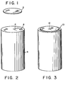
- a flexible disc 2 such as, for example, a stainless steel disc, is disposed and secured over the bottom 4 of a galvanic cell container 6, said bottom 4 having an off-centre vent orifice 8.
- flexible disc 2 is secured proximal its peripheral edge 10 to the bottom 4 of cell container 6 using conventional welding means.
- a small spot weld 12 about 0.025 inch in diameter, is placed at the centre of disc 2, thereby securing a small central area of disc 2 to bottom 4 of cell container 6.
- Pressure buildup within cell container 6 will vent through orifice 8 and exert pressure against flexible disc 2 where it will be substantially concentrated around spot weld 12.
- a pressure buildup to as low as 75 psi can be sufficient to rupture the area around spot weld 12, thereby providing a permanent vent in the cell container.
Landscapes
- Engineering & Computer Science (AREA)
- Power Engineering (AREA)
- Chemical & Material Sciences (AREA)
- Chemical Kinetics & Catalysis (AREA)
- Electrochemistry (AREA)
- General Chemical & Material Sciences (AREA)
- Microelectronics & Electronic Packaging (AREA)
- Gas Exhaust Devices For Batteries (AREA)
- Primary Cells (AREA)
Applications Claiming Priority (2)
| Application Number | Priority Date | Filing Date | Title |
|---|---|---|---|
| US27890181A | 1981-06-29 | 1981-06-29 | |
| US278901 | 1981-06-29 |
Publications (1)
| Publication Number | Publication Date |
|---|---|
| EP0068836A1 true EP0068836A1 (fr) | 1983-01-05 |
Family
ID=23066869
Family Applications (1)
| Application Number | Title | Priority Date | Filing Date |
|---|---|---|---|
| EP82303316A Ceased EP0068836A1 (fr) | 1981-06-29 | 1982-06-25 | Soupape de sécurité non-réobturable pour cellules électrochimiques |
Country Status (2)
| Country | Link |
|---|---|
| EP (1) | EP0068836A1 (fr) |
| JP (1) | JPS587758A (fr) |
Cited By (3)
| Publication number | Priority date | Publication date | Assignee | Title |
|---|---|---|---|---|
| EP0918343A4 (fr) * | 1996-08-06 | 1999-11-17 | Toyo Kohan Co Ltd | Element de clapet de securite pour condensateur et couvercle de boitier de condensateur equipe d'un clapet de securite |
| US6150037A (en) * | 1996-02-15 | 2000-11-21 | Toyo Kohan Co., Ltd | Cladding material |
| CN107611313A (zh) * | 2017-10-07 | 2018-01-19 | 珠海市至力电池有限公司 | 扣式电池防爆盖 |
Families Citing this family (1)
| Publication number | Priority date | Publication date | Assignee | Title |
|---|---|---|---|---|
| JP4957458B2 (ja) | 2007-08-27 | 2012-06-20 | 株式会社Jvcケンウッド | ボイスコイル及びスピーカ |
Citations (4)
| Publication number | Priority date | Publication date | Assignee | Title |
|---|---|---|---|---|
| US2380964A (en) * | 1943-06-30 | 1945-08-07 | Westinghouse Electric Corp | Safety device |
| US3524112A (en) * | 1967-02-14 | 1970-08-11 | Wicon Kondensatorfabrik Copenh | Gas emitting structure for an electrolytic circuit component |
| US3909303A (en) * | 1973-01-30 | 1975-09-30 | Power Conversion Inc | Battery construction with provision for venting its contents |
| FR2357074A1 (fr) * | 1976-06-28 | 1978-01-27 | Mallory & Co Inc P R | Dispositif hermetique de ventilation d'appareils electriques |
-
1982
- 1982-06-25 EP EP82303316A patent/EP0068836A1/fr not_active Ceased
- 1982-06-28 JP JP57111407A patent/JPS587758A/ja active Pending
Patent Citations (4)
| Publication number | Priority date | Publication date | Assignee | Title |
|---|---|---|---|---|
| US2380964A (en) * | 1943-06-30 | 1945-08-07 | Westinghouse Electric Corp | Safety device |
| US3524112A (en) * | 1967-02-14 | 1970-08-11 | Wicon Kondensatorfabrik Copenh | Gas emitting structure for an electrolytic circuit component |
| US3909303A (en) * | 1973-01-30 | 1975-09-30 | Power Conversion Inc | Battery construction with provision for venting its contents |
| FR2357074A1 (fr) * | 1976-06-28 | 1978-01-27 | Mallory & Co Inc P R | Dispositif hermetique de ventilation d'appareils electriques |
Cited By (4)
| Publication number | Priority date | Publication date | Assignee | Title |
|---|---|---|---|---|
| US6150037A (en) * | 1996-02-15 | 2000-11-21 | Toyo Kohan Co., Ltd | Cladding material |
| EP0918343A4 (fr) * | 1996-08-06 | 1999-11-17 | Toyo Kohan Co Ltd | Element de clapet de securite pour condensateur et couvercle de boitier de condensateur equipe d'un clapet de securite |
| US6257267B1 (en) | 1996-08-06 | 2001-07-10 | Toyo Kohan Co., Ltd. | Safety valve element for capacitor and capacitor case lid with safety valves |
| CN107611313A (zh) * | 2017-10-07 | 2018-01-19 | 珠海市至力电池有限公司 | 扣式电池防爆盖 |
Also Published As
| Publication number | Publication date |
|---|---|
| JPS587758A (ja) | 1983-01-17 |
Similar Documents
| Publication | Publication Date | Title |
|---|---|---|
| CA1134904A (fr) | Accumulateur non aqueux a materiau souple poreux renfermant un agent immobilisateur | |
| EP0049080B1 (fr) | Cellule électrochimique à soupape d'échappement de sécurité et sa méthode de fabrication | |
| US5418084A (en) | Electrochemical cell having a safety vent closure | |
| US4421834A (en) | Liquid cathode cells with a glass fiber separator | |
| US4664989A (en) | Liquid cathode cell system employing a coiled electrode assembly | |
| JPS59500152A (ja) | 電気化学電池 | |
| EP0100487B1 (fr) | Cellule électrochimique avec soupape d'échappement de sécurité et sa méthode de fabrication | |
| US5225291A (en) | Deferred actuated battery assembly | |
| US4592970A (en) | Electrochemical cell having a safety vent closure | |
| US4444855A (en) | Non-aqueous electrochemical cell | |
| EP0158104B1 (fr) | Procédé pour la fabrication d'un élément électrochimique | |
| US5015542A (en) | Electrochemical cell having a safety vent closure | |
| EP0138323A1 (fr) | Elément galvanique revêtu de matériau intumescent | |
| US4437231A (en) | Method of making an electrochemical cell having a safety vent closure | |
| US4794056A (en) | Coiled electrode assembly cell construction with telescopic terminal tab | |
| EP0049081B1 (fr) | Cellule électrochimique et sa méthode de fabrication | |
| US4048392A (en) | Crimp seal using polyphenylene sulfide plastic with an aluminum terminal pan | |
| US4169920A (en) | Hermetically sealed electrochemical battery | |
| US4400453A (en) | Non-aqueous electrochemical cell | |
| US4672010A (en) | Terminal pin-collector plate assembly for hermetically sealed cells | |
| US4532705A (en) | Method of making an electrochemical cell having a resealable vent closure | |
| EP0068837A1 (fr) | Cellule électrochimique | |
| US3902922A (en) | Conductive coated vented cathode collector for thin flat cells | |
| JPS587758A (ja) | 電気化学電池用の非再密封型安全ガス抜き穴 | |
| US3278334A (en) | Anode limited sealed secondary battery having an auxiliary electrode |
Legal Events
| Date | Code | Title | Description |
|---|---|---|---|
| PUAI | Public reference made under article 153(3) epc to a published international application that has entered the european phase |
Free format text: ORIGINAL CODE: 0009012 |
|
| AK | Designated contracting states |
Designated state(s): CH DE FR GB LI |
|
| 17P | Request for examination filed |
Effective date: 19830201 |
|
| STAA | Information on the status of an ep patent application or granted ep patent |
Free format text: STATUS: THE APPLICATION HAS BEEN REFUSED |
|
| 18R | Application refused |
Effective date: 19850704 |
|
| RIN1 | Information on inventor provided before grant (corrected) |
Inventor name: PETERSON, GORDON EDWARD |