EP0068940B1 - Source primaire à réutilisation de fréquences - Google Patents
Source primaire à réutilisation de fréquences Download PDFInfo
- Publication number
- EP0068940B1 EP0068940B1 EP82401015A EP82401015A EP0068940B1 EP 0068940 B1 EP0068940 B1 EP 0068940B1 EP 82401015 A EP82401015 A EP 82401015A EP 82401015 A EP82401015 A EP 82401015A EP 0068940 B1 EP0068940 B1 EP 0068940B1
- Authority
- EP
- European Patent Office
- Prior art keywords
- junction
- reception
- access
- ghz
- horn
- Prior art date
- Legal status (The legal status is an assumption and is not a legal conclusion. Google has not performed a legal analysis and makes no representation as to the accuracy of the status listed.)
- Expired
Links
Images

Classifications
-
- H—ELECTRICITY
- H01—ELECTRIC ELEMENTS
- H01P—WAVEGUIDES; RESONATORS, LINES, OR OTHER DEVICES OF THE WAVEGUIDE TYPE
- H01P1/00—Auxiliary devices
- H01P1/20—Frequency-selective devices, e.g. filters
- H01P1/213—Frequency-selective devices, e.g. filters combining or separating two or more different frequencies
-
- G—PHYSICS
- G01—MEASURING; TESTING
- G01S—RADIO DIRECTION-FINDING; RADIO NAVIGATION; DETERMINING DISTANCE OR VELOCITY BY USE OF RADIO WAVES; LOCATING OR PRESENCE-DETECTING BY USE OF THE REFLECTION OR RERADIATION OF RADIO WAVES; ANALOGOUS ARRANGEMENTS USING OTHER WAVES
- G01S3/00—Direction-finders for determining the direction from which infrasonic, sonic, ultrasonic or electromagnetic waves, or particle emission, not having a directional significance, are being received
- G01S3/02—Direction-finders for determining the direction from which infrasonic, sonic, ultrasonic or electromagnetic waves, or particle emission, not having a directional significance, are being received using radio waves
- G01S3/14—Systems for determining direction or deviation from predetermined direction
- G01S3/146—Systems for determining direction or deviation from predetermined direction by comparing linear polarisation components
-
- H—ELECTRICITY
- H01—ELECTRIC ELEMENTS
- H01Q—ANTENNAS, i.e. RADIO AERIALS
- H01Q25/00—Antennas or antenna systems providing at least two radiating patterns
- H01Q25/04—Multimode antennas
Definitions
- the present invention relates to a primary source with very wide band for space communications antenna and more specifically for earth station antenna operating with frequency reuse, that is to say with use of the same frequency band in two orthogonal polarizations.
- the uplink In the first group, the uplink, called “transmission” in the following, is between 5.925 and 6.425 GHz and the downlink, called “reception” in the following, is between 3.7 and 4.2 GHz. In the second group, the uplink or “transmission” is between 14 and 14.5 GHz and the downlink or “reception” between 10.95 and 11.7 GHz.
- the known primary sources two examples of which will be given below do not allow these bands to be passed, all the more so as the desired performances are greater than or at least equal to those obtained with the existing primary sources with frequency reuse.
- the object of the present invention is a primary source requiring a mode extractor and capable of working in the new frequency bands indicated above.
- This primary source according to the invention is obtained, in particular, by arranging the mode extractor in the reception channel only.
- the main known embodiments of primary sources with frequency reuse using a mode extractor can be classified into two categories which differ from one another by the use or not of polarizers covering both the bands 3.7 - 4.2 GHz and 5.925 - 6.425 GHz and which will be described in the following broadband polarizers as opposed to polarizers covering narrower bands such as 3.7 - 4.2 GHz, 5.925 - 6.425 GHz, 3.4 - 4.8 GHz , 5.85 - 7.075 GHz.
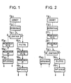
- Figure 1 relates to a primary source not using a broadband polarizer.
- the polarizers are distinct, one for the "reception” band 3.7 - 4.2 GHz and one for the "transmission” band 5.925 - 6.425 GHz.
- FIG. 1 represents a horn 1a coupled, through a mode extractor, to the first access (1.) of a band separator also called orthomode junction, 3 . (orthomode junction or OMJ in Anglo-Saxon literature). From the second and third accesses (2. and 3.) of the orthomode junction 3, two channels leave: a transmitting channel and a receiving channel.
- orthomode junction or OMJ in Anglo-Saxon literature
- the cornet la is a classic grooved horn (corrugated horn in Anglo-Saxon literature): it covers the two bands 3.7 - 4.2 GHz and 5.925 - 6.425 GHz.
- the role of the mode extractor 2a (higher mode coupler in the Anglo-Saxon literature) is to allow the extraction of the signals of the modes specific to the pursuit and which are in the band "reception” 3,7 - 4,2 GHz. Since it also receives signals from the "transmit” band to transmit them to the horn, it must also pass the "transmit” band 5.925 - 6.425 GHz. It is therefore a very important element and one that must be very effective. It is therefore difficult to achieve due to its large bandwidth:
- the role of the orthomode junction 3a is to group the reception and the emission so as to have only one horn; it is carried out in various ways generally from filters or directional couplers.
- the reception channel comprises, in series between the third port of junction 3 a and the two "reception" ports of the primary source, a rejection filter, 16 r , a polarizer 17 r , an n polarizer, 18 r , and a polarization duplexer 19 r whose horizontal and vertical polarization ports constitute the two "reception" ports of the primary source.
- the rejection filter, 16 r stops the transmission band (5.925 - 6.425 GHz) allowing only the reception band (3.7 - 4.2 GHz) to pass.
- the polarizer, 18 r type allows electro-mechanical compensation for depolarization when the station in which the primary source is located is equipped with a system for detecting this depolarization; it therefore does not always exist in known arrangements.
- the polarization duplexer (orthomode transducer or OMT in the Anglo-Saxon literature), 19 r , makes it possible to separate the two orthogonal linear polarizations of the wave coming from the polarizers 17 r , 18 r .
- the transmission channel comprises, in series between the two "transmission” accesses of the primary source and the second access of the junction 3 a : a polarization duplexer 19 8 whose horizontal polarization and vertical polarization accesses constitute the two "transmission” accesses "from the primary source, a polarizer ⁇ , 18 e and a polarizer ⁇ / 2, 17 e .
- the polarization duplexer 19 e makes it possible to mix the two orthogonal linear polarizations of the waves applied to its two polarization ports: the polarizer 18 e of the type has the same role as the polarizer 18 r of the reception channel; as for the polarizer 17 e which is a type polarizer it only covers the band 5.925 - 6.425 GHz where Fmax / Fmin - 1.0843.
- FIG. 2 relates to a known primary source using a broadband polarizer, common to the transmission and reception channels and therefore covering the bands 3.7 - 4.2 GHz and 5.925 - 6.425 GHz.
- FIG. 2 shows a horn 1a coupled through a manual extractor 2 is followed by a broadband polarizer 27, type itself followed by a polarizer, 28, of the type at the first access of an orthomode junction 3 8 .
- Two and third ports of the orthomode junction 3a leave two channels: a transmission channel and a reception channel.
- the horn 1a and the mode extractor 2 a of FIG. 2 are respectively identical to those of FIG. 1.
- the broadband polarizer covers the bands 3.7 - 4.2 GHz and 5.925 - 6.425 GHz (i.e. it is a difficult element to achieve and therefore very expensive.
- the n-type polarizer, 28 has the same role as the polarizers 18 r , 18 e in FIG. 1, but is more difficult to achieve due to its larger operating frequency band.
- the orthomode junction 3 a has the same role as the junction 3 a in FIG. 1.
- the reception channel of the primary source according to FIG. 2 comprises in series a rejection filter 16 r and a polarization duplexer 19 r identical both as regards their constitution and their role to the filter 16 r and to the duplexer 19 r according to the figure 1.
- the transmission channel of the primary source according to FIG. 2 comprises a polarization duplexer 19 e , identical to the duplexer 19 e in FIG. 1.
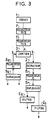
- FIG. 3 relates to a primary source intended to operate at frequencies ranging from 3.4 to 7.075 GHz, that is to say corresponding to more than one octave:
- FIG. 3 represents a horn 1 to which the first port of an orthomode junction 3 is connected through two polarizers 7 and 7 '.
- This embodiment has the advantage to minimize the distance between the quasi-optical filter of the orthomode junction 3 (or bands separator) and filters rejection 6a, 6b; this makes it possible to avoid the resonances which would be due to the "emission" signals which could have passed through the quasi-optical filter of the orthomode junction 3 in the direction of the reception channel ".
- two channels leave: a transmission channel and a reception channel.
- the horn 1 is a horn with two types of regularly alternating grooves whose depth decreases, for each of the two types, from the neck of the horn towards its opening. Cornets of this type are described in French patent application No. 7911316 of May 4, 1979.
- the Figure 4 shows, in a longitudinal sectional view, how is made the horn 1 of Figure 3; this horn has an opening diameter of 1000 mm and a length of the grooved part of 3000 mm; in Figure 4 the proportions have not been respected to better highlight the variation in depth of the grooves.
- the orthomode junction 3 comprises a first circular waveguide, one end of which is coupled to the horn 1 and the other end of which constitutes the access to the reception channel; this first circular guide has four lateral slots arranged at the same level and offset by 90 ° with respect to each other; rectangular guides connect these four slots in opposite pairs, through two magic tees, to the opposite pairs of four side slots of a second circular guide; this second circular guide, the lateral slots of which are arranged as on the first guide, is short-circuited at one of its ends and at its other end which constitutes the access to the transmission channel.
- FIG. 3 shows that the reception channel comprises, between the third port of junction 3 and the two reception ports of the primary source: a mode extractor, 2, an n-type polarizer, 8 r , a polarization duplexer, 9r the two polarization ports of which are respectively coupled to the two reception ports of the primary source by two rejector filters 6 8 , 6 b .
- the transmission channel for its part, comprises, in series from the two transmission accesses of the primary source, a polarization duplexer, 9 e , and a ⁇ type polarizer, 8 e , coupled to the second access of the orthomode junction 3 .
- the mode extractor, 2 unlike the mode extractors, 2a, in FIGS. 1 and 2 is located only in the reception channel; it therefore only has to cover the band 3.4 - 4.8 GHz, (Fmax / Fmin - 1.41) which is a band much narrower than that of the other known versions. It also has the advantage of not being crossed by the power of the transmission band. Therefore, its design is simpler and lower cost for better performance.
- the reception polarizer 8 r of FIG. 3 has to cover a narrower band than the reception polarizers according to FIG. 2; its design is therefore also simpler and its cost less for better performance.
- the polarization duplexers reception 9 r , and transmission, 9 e are unchanged compared to the other existing known versions (FIGS. 1 and 2).
- the band it has to cover is limited to the emission band and is therefore significantly narrower than that of the polarizers of the aforementioned broadband version (FIG. 2). It is therefore also simpler and of a lower cost price for better performance, that is to say for lower losses and a better ellipticity rate.
- the invention is not limited to the examples described using FIGS. 3 to 5, this is how it can be applied to other frequency bands.
Landscapes
- Physics & Mathematics (AREA)
- Engineering & Computer Science (AREA)
- General Physics & Mathematics (AREA)
- Radar, Positioning & Navigation (AREA)
- Remote Sensing (AREA)
- Waveguide Aerials (AREA)
- Control Of Motors That Do Not Use Commutators (AREA)
- Waveguide Switches, Polarizers, And Phase Shifters (AREA)
- Aerials With Secondary Devices (AREA)
- Input Circuits Of Receivers And Coupling Of Receivers And Audio Equipment (AREA)
- Burglar Alarm Systems (AREA)
Description
- La présente invention se rapporte à une source primaire à très large bande pour antenne de communications spatiales et plus précisément pour antenne de station terrienne fonctionnant avec réutilisation de fréquences, c'est-à-dire avec utilisation d'une même bande de fréquences dans deux polarisations orthogonales.
- Les communications spatiales utilisent actuellement deux groupes de bandes de fréquences. Dans le premier groupe la liaison montante, appelée "émission" dans ce qui suit, s'effectue entre 5,925 et 6,425 GHz et la liaison descendante, appelée "réception" dans ce qui suit, s'effectue entre 3,7 et 4,2 GHz. Dans le second groupe la liaison montante ou "émission" s'effectue entre 14 et 14,5 GHz et la liaison descendante ou "réception" entre 10,95 et 11,7 GHz.
- Depuis peu, il est question d'élargir les bandes de fréquences pour permettre d'augmenter la capacité de transmission; or ces nouvelles bandes sont nettement plus larges puisque la bande pour l'émission va de 5,85 à 7,075 GHz et la bande pour la "réception" de 3,4 à 4,2 GHz et de 4,5 à 4,8 GHz.
- Les sources primaires connues, dont deux exemples seront donnés plus loin ne permettent pas de passer ces bandes, d'autant plus que les performances souhaitées sont supérieures ou au moins égales à celles obtenues avec les sources primaires existantes à réutilisation de fréquences.
- Un brevet américain US-A-3 696 434 décrit une structure où les éléments se trouvent connectés dans la suite ci-après:
- - un cornet à rainures,
- - une section de guide où est appliqué le signal à transmettre (1,75 1,85 GHz),
- - une transition,
- - une section de guide qui laisse passer le signal à recevoir (2,2 - 2,3 GHz) et arrête le signal à transmettre (1,75 1,85 GHz),
- - une transition,
- - une section de guide d'où sont extraites les ondes différence du signal à recevoir (modes TE11 + TM11 et TE2Q) grâce à des sondes suivies de circuits hydrides afin de passer en polarisation circulaire,
- - une section de guide d'où est extrait le mode TE10 du signal à recevoir grâce à un coupleur orthogonal suivi d'un circuit hybride afin de séparer les deux polarisations linéaires et de passer en polarisation circulaire.
- L'objet de la présente invention est une source primaire nécessitant un extracteur de mode et capable de travailler dans les nouvelles bandes de fréquences indiquées ci-avant.
- Cette source primaire selon l'invention est obtenue, en particulier, en disposant l'extracteur de mode dans la voie réception uniquement.
- Pour permettre un fonctionnement dans une très large bande, l'invention propose une source primaire à réutilisation de fréquences, comprenant:
- - un cornet rainuré,
- - une jonction orthomode,
- - une voie de réception reliée à un troisième accès de ladite jonction, ledit accès étant couplé à l'entrée d'un extracteur de modes supérieurs dont la sortie est connectée à une entrée d'un duplexeur de réception,
- - et un duplexeur d'émission relié en sortie à un deuxième accès de ladite jonction,
caractérisé en ce - - qu'un polariseur 1 d'émission et un polariseur ! de réception sont connectés en série et sont intercalés entre l'accès audit cornet et un premier accès de ladite jonction,
- - qu'un filtre est relié à chaque sortie du duplexeur de réception,
- - que le cornet comprend deux types de rainures régulièrement alternées dont la profondeur diminue, pour chacun des deux types, du col vers l'ouverture, et
- - que ladite jonction comporte un dipole métallique croisé perpendiculaire à l'axe longitudinal du guide circulaire dont l'extrémité forme le premier accès de la jonction, ce dipole étant disposé en amont de la voie de réception.
- L'invention sera mieux comprise et d'autres caractéristiques apparaîtront à l'aide de la description ci-après et des figures s'y rapportant qui représentent:
- - les figures 1 et 2 des sources primaires selon l'art connu,
- - la figure 3 une source primaire selon l'invention,
- - les figures 4 et 5 des vues de détail de certains éléments selon la figure 3.
- Sur les différentes figures les éléments semblables portent les même repères.
- Les principales réalisations connues de sources primaires à réutilisation de fréquences utilisant un extracteur de mode peuvent être classées en deux catégories qui se différencient entre elles par l'emploi ou non de polariseurs couvrant à la fois les bandes 3,7 - 4,2 GHz et 5,925 - 6,425 GHz et qui seront dits dans ce qui suit polariseurs à large bande par opposition à des polariseurs couvrant des bandes plus étroites telles que 3,7 - 4,2 GHz, 5,925 - 6,425 GHz, 3,4 - 4,8 GHz, 5,85 - 7,075 GHz.
- La figure 1 est relative à une source primaire n'utilisant pas un polariseur à large bande. Dans cette source les polariseurs sont distincts un pour la bande "réception" 3,7 - 4,2 GHz et un pour la bande "émission" 5,925 - 6,425 GHz.
- La figure 1 représente un cornet 1a couplé, à travers un extracteur de mode, au premier accès (1.) d'un séparateur de bandes aussi appelé jonction orthomode, 3. (orthomode junction ou OMJ dans la littérature anglo-saxonne). Des deuxième et troisième accès (2. et 3.) de la jonction orthomode 3, partent deux voies: une voie émission et une voie réception.
- Le cornet la est un cornet à rainures (corrugated horn dans la littérature anglo-saxonne) classique: il couvre les deux bandes 3,7 - 4,2 GHz et 5,925 - 6,425 GHz.
- L'extracteur de mode 2a (higher mode coupler dans la littérature anglo-saxonne) a pour rôle de permettre d'extraire les signaux des modes spécifiques à la poursuite et qui se trouvent dans la bande "réception" 3,7 - 4,2 GHz. Comme il reçoit également les signaux de la bande "émission" pour les transmettre au cornet, il doit passer aussi la bande "émission" 5,925 - 6,425 GHz. C'est donc un élément très important et qui doit être très performant. Il est par conséquent difficile à réaliser en raison de sa large bande passante:
- 3,7 - 4,2 GHz et 5,925 - 6,425 GHz soit

- Le rôle de la jonction orthomode 3a est de grouper la réception et l'émission pour n'avoir qu'un seul cornet; elle est réalisée de diverses façons généralement à partir de filtres ou de coupleurs directifs.
- La voie réception comporte, en série entre le troisième accès de la jonction 3a et les deux accès "réception" de la source primaire un filtre de réjection, 16r, un polariseur

- Le filtre de réjection, 16r, arrête la bande émission (5,925 - 6,425 GHz) ne laissant passer que la bande réception (3,7 - 4,2 GHz).
- Le polariseur, 17r, ne couvre que la bande 3,7 - 4,2 GHz ou Fmax/Fmin: 4,2/3,7 = 1,135; c'est un polariseur de type qui permet de transformer le champ à polarisation circulaire provenant du cornet en un champ à polarisation rectiligne.
- Le polariseur, 18r, de type

- Le duplexeur de polarisation (orthomode transducer ou OMT dans la littérature anglo-saxonne), 19r, permet de séparer les deux polarisations linéaires orthogonales de l'onde provenant des polariseurs 17r, 18r.
- La voie émission comporte, en série entre les deux accès "émission" de la source primaire et le deuxième accès de la jonction 3a: un duplexeur de polarisation 198 dont les accès de polarisation horizontale et de polarisation verticale constituent les deux accès "émission" de la source primaire, un polariseur π, 18e et un polariseur π/2, 17e.
- Dans la voie émission le duplexeur de polarisation 19e permet de mélanger les deux polarisations linéaires orthogonales des ondes appliquées sur ses deux accès de polarisation: le polariseur 18e de type


- La figure 2 est relative à une source primaire connue utilisant un polariseur à large bande, commun aux voies émission et réception et couvrant donc les bandes 3,7 - 4,2 GHz et 5,925 - 6,425 GHz.
- La figure 2 représente un cornet 1a couplé, à travers un extracteur de mode 2a , suivi d'un polariseur à large bande, 27, de type


- Le cornet 1a et l'extracteur de mode 2a de la figure 2 sont respectivement identiques à ceux de la figure 1.
- Le polariseur à large bande, comme il a été indiqué plus haut, couvre les bandes 3,7 - 4,2 GHz et 5,925 - 6,425 GHz (soit

- Le polariseur de type n, 28, a le même rôle que les polariseurs 18r, 18e de la figure 1 mais est plus difficile à réaliser en raison de sa plus grande bande de fréquences de fonctionnement.
- La jonction orthomode 3a a le même rôle que la jonction 3a de la figure 1.
- La voie réception de la source primaire selon la figure 2 comporte en série un filtre de réjection 16r et un duplexeur de polarisation 19r identiques tant en ce qui concerne leur constitution que leur rôle au filtre 16r et au duplexeur 19r selon la figure 1. De même la voie émission de la source primaire selon la figure 2 comporte un duplexeur de polarisation 19e, identique au duplexeur 19e de la figure 1.
- La figure 3 est relative à une source primaire destinée à fonctionner à des fréquences allant de 3,4 à 7,075 GHz, c'est-à-dire correspondant à plus d'une octave:

- La figure 3 représente un cornet 1 auquel est connecté le premier accès d'une jonction orthomode 3 au travers de deux polarisateurs 7 et 7'.
- Il est à noter que, pour des raisons de facilité de réalisation, deux polariseurs de type

- Des deuxième et troisième accès de la jonction 3 partent deux voies: une voie émission et une voie réception.
- Le cornet 1 est un cornet à deux types de rainures régulièrement alternées dont la profondeur diminue, pour chacun des deux types, du col du cornet vers son ouverture. Des cornets de ce type sont décrits dans la demande de brevet français n° 7911316 du 4 mai 1979. La figure 4 montre, dans une vue en coupe longitudinale, comment est constitué le cornet 1 de la figure 3; ce cornet présente un diamètre d'ouverture de 1000 mm et une longueur de la partie rainurée de 3000 mm; sur la figure 4 les proportions n'ont pas été respectées pour mieux faire ressortir la variation de profondeur des rainures.
- La jonction orthomode 3 comporte un premier guide d'ondes circulaire dont une extrémité est couplée au cornet 1 et dont l'autre extrémité constitue l'accès de la voie réception; ce premier guide circulaire présente quatre fentes latérales disposées à un même niveau et décalées de 90° les unes par rapport aux autres; des guides rectangulaires relient ces quatre fentes par paires opposées, à travers deux Tés-magiques, aux paires opposées de quatre fentes latérales d'un second guide circulaire; ce second guide circulaire, dont les fentes latérales sont disposées comme sur le premier guide, est court- circuité à l'une de ses extrémités et a son autre extrémité qui constitue l'accès de la voie émission. A l'intérieur du premier guide circulaire de la jonction orthomode 3, entre les fentes latérales et l'accès de la voie réception, se trouve un jeu de filtres quasi-optiques; chacun de ces filtres est, comme le montre la figure 5 constitué par un dipôle métallique croisé, 13b, déposé sur un support diélectrique,13a , formé d'une feuille en oxyde de beryllium, solidaire de la paroi du guide cylindrique; cette feuille est perpendiculaire à l'axe longitudinal du guide circulaire.
- La figure 3 montre que la voie réception comporte, entre le troisième accès de la jonction 3 et les deux accès réception de la source primaire: un extracteur de mode, 2, un polariseur de type n, 8r, un duplexeur de polarisation, 9r dont les deux accès de polarisation sont respectivement couplés aux deux accès de réception de la source primaire par deux filtres réjecteurs 68, 6b. La voie émission, quant à elle, comporte, en série à partir des deux accès émission de la source primaire, un duplexeur de polarisation, 9e, et un polariseur de type π, 8e, couplé au deuxième accès de la jonction orthomode 3.
- Il est à remarquer sur la figure 3 que l'extracteur de mode, 2, à l'inverse des extracteurs de mode, 2a, des figures 1 et 2 se trouve situé uniquement dans la voie réception; il n'a donc à couvrir que la bande 3,4 - 4,8 GHz, (Fmax/Fmin - 1,41) qui est une bande nettement plus étroite que celle des autres versions connues. Il présente de plus l'avantage de ne pas être traversé par la puissance de la bande émission. De ce fait, sa conception est plus simple et son coût moindre pour de meilleurs performances.
- Le polariseur réception 8r de la figure 3 a à couvrir une bande plus étroite que les polariseurs réception selon la figure 2; sa conception est donc également plus simple et son coût moindre pour des performances meilleures.
- Les duplexeurs de polarisation réception 9r, et émission, 9e, sont sans changement par rapport aux autres versions connues existantes (figures 1 et 2).
- Quant au polariseur émission 8e la bande qu'il a à couvrir est limitée à la bande émission

- L'invention n'est pas limitée aux exemples décrits à l'aide des figures 3 à 5, c'est ainsi qu'elle peut s'appliquer à d'autres bandes de fréquences.
Claims (2)
caractérisée en ce
Priority Applications (1)
| Application Number | Priority Date | Filing Date | Title |
|---|---|---|---|
| AT82401015T ATE40495T1 (de) | 1981-06-11 | 1982-06-04 | Primaerstrahler fuer frequenz-doppelausnutzung. |
Applications Claiming Priority (2)
| Application Number | Priority Date | Filing Date | Title |
|---|---|---|---|
| FR8111481A FR2507826A1 (fr) | 1981-06-11 | 1981-06-11 | Source primaire a reutilisation de frequences |
| FR8111481 | 1981-06-11 |
Publications (2)
| Publication Number | Publication Date |
|---|---|
| EP0068940A1 EP0068940A1 (fr) | 1983-01-05 |
| EP0068940B1 true EP0068940B1 (fr) | 1989-01-25 |
Family
ID=9259392
Family Applications (1)
| Application Number | Title | Priority Date | Filing Date |
|---|---|---|---|
| EP82401015A Expired EP0068940B1 (fr) | 1981-06-11 | 1982-06-04 | Source primaire à réutilisation de fréquences |
Country Status (7)
| Country | Link |
|---|---|
| US (1) | US4507665A (fr) |
| EP (1) | EP0068940B1 (fr) |
| JP (1) | JPS57212804A (fr) |
| AT (1) | ATE40495T1 (fr) |
| CA (1) | CA1190317A (fr) |
| DE (1) | DE3279408D1 (fr) |
| FR (1) | FR2507826A1 (fr) |
Families Citing this family (2)
| Publication number | Priority date | Publication date | Assignee | Title |
|---|---|---|---|---|
| RU2620893C1 (ru) * | 2016-03-23 | 2017-05-30 | Федеральное Государственное Унитарное Предприятие Ордена Трудового Красного Знамени Научно-Исследовательский Институт Радио (Фгуп Ниир) | Устройство для приема ортогональных линейно поляризованных волн |
| RU2638902C1 (ru) * | 2016-07-01 | 2017-12-18 | Федеральное Государственное Унитарное Предприятие Ордена Трудового Красного Знамени Научно-Исследовательский Институт Радио (Фгуп Ниир) | Устройство для работы на двух круговых поляризациях в двух диапазонах частот |
Family Cites Families (12)
| Publication number | Priority date | Publication date | Assignee | Title |
|---|---|---|---|---|
| US3560976A (en) * | 1968-08-21 | 1971-02-02 | Rca Corp | Feed system |
| US3665481A (en) * | 1970-05-12 | 1972-05-23 | Nasa | Multi-purpose antenna employing dish reflector with plural coaxial horn feeds |
| US3696434A (en) * | 1971-01-15 | 1972-10-03 | Radiation Inc | Independent mode antenna feed system |
| US3731236A (en) * | 1972-08-17 | 1973-05-01 | Gte Sylvania Inc | Independently adjustable dual polarized diplexer |
| GB1498905A (en) * | 1975-04-11 | 1978-01-25 | Marconi Co Ltd | Corrugated horns |
| DE2757115C2 (de) * | 1977-12-21 | 1987-05-27 | Siemens AG, 1000 Berlin und 8000 München | Modenkoppler |
| US4162463A (en) * | 1977-12-23 | 1979-07-24 | Gte Sylvania Incorporated | Diplexer apparatus |
| US4233576A (en) * | 1978-05-16 | 1980-11-11 | Harris Corporation | Automatic polarization decoupling network |
| IT1160267B (it) * | 1978-11-27 | 1987-03-11 | Sits Soc It Telecom Siemens | Disposizione circuitale per rilevare l'errore di puntamento dell'antenna in un sistema di telecomunicazioni |
| US4345255A (en) * | 1978-12-25 | 1982-08-17 | Kokusai Denshin Denwa Co., Ltd. | Antenna feed system |
| FR2455803A1 (fr) * | 1979-05-04 | 1980-11-28 | Thomson Csf | Cornet a rainures de differentes profondeurs et antenne comportant un tel cornet |
| DE2932626C2 (de) * | 1979-08-11 | 1985-01-31 | ANT Nachrichtentechnik GmbH, 7150 Backnang | Viertornetzwerk zur Trennung zweier aus doppelt polarisierten Frequenzbändern bestehenden Signalen |
-
1981
- 1981-06-11 FR FR8111481A patent/FR2507826A1/fr active Granted
-
1982
- 1982-06-04 AT AT82401015T patent/ATE40495T1/de active
- 1982-06-04 DE DE8282401015T patent/DE3279408D1/de not_active Expired
- 1982-06-04 EP EP82401015A patent/EP0068940B1/fr not_active Expired
- 1982-06-09 CA CA000404817A patent/CA1190317A/fr not_active Expired
- 1982-06-09 US US06/386,600 patent/US4507665A/en not_active Expired - Fee Related
- 1982-06-09 JP JP57097904A patent/JPS57212804A/ja active Granted
Non-Patent Citations (1)
| Title |
|---|
| AP-S INTERNATIONAL SYMPOSIUM, 21 juin 1977, pages 341-344, Institute of Electrical and Electronics Engineers, Stanford Californie IEEE, New York, USA R.W. GRUNER: "Compact dual-polarized diplexers for 4/6-GHz earth station applications" * |
Also Published As
| Publication number | Publication date |
|---|---|
| DE3279408D1 (en) | 1989-03-02 |
| EP0068940A1 (fr) | 1983-01-05 |
| US4507665A (en) | 1985-03-26 |
| CA1190317A (fr) | 1985-07-09 |
| FR2507826B1 (fr) | 1985-05-03 |
| FR2507826A1 (fr) | 1982-12-17 |
| JPS57212804A (en) | 1982-12-27 |
| JPH0134405B2 (fr) | 1989-07-19 |
| ATE40495T1 (de) | 1989-02-15 |
Similar Documents
| Publication | Publication Date | Title |
|---|---|---|
| FR2857165A1 (fr) | Antenne bi-bande avec double acces | |
| EP0880193B1 (fr) | Source d'antenne pour l'emission et la réception d'ondes hyperfréquences | |
| EP0045682B1 (fr) | Transducteur d'antenne pour antenne d'émission-réception | |
| EP0098192B1 (fr) | Dispositif de multiplexage pour grouper deux bandes de fréquences | |
| FR2831997A1 (fr) | Module guide d'ondes separateur en frequence a polarisation circulaire double et emetteur-recepteur le comportant | |
| FR2524209A1 (fr) | Dispositif guide d'ondes, capable de separer des signaux de radiofrequence a double bande et double polarisation | |
| FR2623020A1 (fr) | Dispositif d'excitation d'un guide d'onde en polarisation circulaire par une antenne plane | |
| EP2195877B1 (fr) | Coupleur-separateur d'emission-reception multibande a large bande de type omt pour antennes de telecommunications hyperfrequences | |
| FR2718292A1 (fr) | Antenne d'émission et/ou de réception de signaux électromagnétiques, en particulier hyperfréquences, et dispositif utilisant une telle antenne. | |
| FR2704358A1 (fr) | Duplexeur de polarissation à guide d'ondes. | |
| FR2824425A1 (fr) | Coupleur coaxial a large bande de jonction a mode orthogonal | |
| EP0377155B1 (fr) | Dispositif rayonnant bifréquence | |
| EP0068940B1 (fr) | Source primaire à réutilisation de fréquences | |
| FR2593644A1 (fr) | Dispositif duplexeur de polarisation et de frequences a trois acces. | |
| FR3083014A1 (fr) | Excitateur radiofrequence d'antenne en reception et transmission | |
| FR2723801A1 (fr) | Diplexeur a intervalle d'un octave entre bandes. | |
| EP0075498A1 (fr) | Filtre à cavités, présentant un couplage entre cavités non adjacentes | |
| FR2515432A1 (fr) | Coupleur de puissance micro-onde de dimensions reduites | |
| FR2818444A1 (fr) | Dispositif de separation de signaux d'emission et de reception | |
| FR2818809A1 (fr) | Dispositif de filtrage d'ondes electromagnetiques | |
| FR2463520A1 (fr) | Reseau quadriporte pour la separation de deux signaux constitues par des bandes de frequences a double polarisation | |
| EP2281320B1 (fr) | Coupleur pour systeme radio frequences multibandes | |
| EP0192186A1 (fr) | Duplexeur de polarisations | |
| WO2024047573A1 (fr) | Jonction orthomode à six ports | |
| EP3035445A1 (fr) | Coupleur de jonction a mode orthogonal et separateur de polarisations et de frequences associe |
Legal Events
| Date | Code | Title | Description |
|---|---|---|---|
| PUAI | Public reference made under article 153(3) epc to a published international application that has entered the european phase |
Free format text: ORIGINAL CODE: 0009012 |
|
| AK | Designated contracting states |
Designated state(s): AT BE CH DE GB IT LI NL SE |
|
| 17P | Request for examination filed |
Effective date: 19830510 |
|
| RAP1 | Party data changed (applicant data changed or rights of an application transferred) |
Owner name: ALCATEL THOMSON FAISCEAUX HERTZIENS SOCIETE ANONYM |
|
| GRAA | (expected) grant |
Free format text: ORIGINAL CODE: 0009210 |
|
| AK | Designated contracting states |
Kind code of ref document: B1 Designated state(s): AT BE CH DE GB IT LI NL SE |
|
| REF | Corresponds to: |
Ref document number: 40495 Country of ref document: AT Date of ref document: 19890215 Kind code of ref document: T |
|
| REF | Corresponds to: |
Ref document number: 3279408 Country of ref document: DE Date of ref document: 19890302 |
|
| GBT | Gb: translation of ep patent filed (gb section 77(6)(a)/1977) | ||
| ITF | It: translation for a ep patent filed | ||
| PLBE | No opposition filed within time limit |
Free format text: ORIGINAL CODE: 0009261 |
|
| STAA | Information on the status of an ep patent application or granted ep patent |
Free format text: STATUS: NO OPPOSITION FILED WITHIN TIME LIMIT |
|
| 26N | No opposition filed | ||
| PGFP | Annual fee paid to national office [announced via postgrant information from national office to epo] |
Ref country code: GB Payment date: 19910424 Year of fee payment: 10 |
|
| PGFP | Annual fee paid to national office [announced via postgrant information from national office to epo] |
Ref country code: SE Payment date: 19910521 Year of fee payment: 10 |
|
| PGFP | Annual fee paid to national office [announced via postgrant information from national office to epo] |
Ref country code: CH Payment date: 19910523 Year of fee payment: 10 |
|
| PGFP | Annual fee paid to national office [announced via postgrant information from national office to epo] |
Ref country code: BE Payment date: 19910605 Year of fee payment: 10 |
|
| PGFP | Annual fee paid to national office [announced via postgrant information from national office to epo] |
Ref country code: DE Payment date: 19910612 Year of fee payment: 10 |
|
| ITTA | It: last paid annual fee | ||
| PGFP | Annual fee paid to national office [announced via postgrant information from national office to epo] |
Ref country code: NL Payment date: 19910630 Year of fee payment: 10 Ref country code: AT Payment date: 19910630 Year of fee payment: 10 |
|
| PG25 | Lapsed in a contracting state [announced via postgrant information from national office to epo] |
Ref country code: GB Effective date: 19920604 Ref country code: AT Effective date: 19920604 |
|
| PG25 | Lapsed in a contracting state [announced via postgrant information from national office to epo] |
Ref country code: SE Effective date: 19920605 |
|
| PG25 | Lapsed in a contracting state [announced via postgrant information from national office to epo] |
Ref country code: LI Effective date: 19920630 Ref country code: CH Effective date: 19920630 Ref country code: BE Effective date: 19920630 |
|
| BERE | Be: lapsed |
Owner name: ALCATEL THOMSON FAISCEAUX HERTZIENS Effective date: 19920630 |
|
| PG25 | Lapsed in a contracting state [announced via postgrant information from national office to epo] |
Ref country code: NL Effective date: 19930101 |
|
| GBPC | Gb: european patent ceased through non-payment of renewal fee |
Effective date: 19920604 |
|
| NLV4 | Nl: lapsed or anulled due to non-payment of the annual fee | ||
| REG | Reference to a national code |
Ref country code: CH Ref legal event code: PL |
|
| PG25 | Lapsed in a contracting state [announced via postgrant information from national office to epo] |
Ref country code: DE Effective date: 19930302 |
|
| EUG | Se: european patent has lapsed |
Ref document number: 82401015.1 Effective date: 19930109 |