EP0068967A1 - Vorrichtung zum Abschotten mit einsetzbaren Trennwänden für Wärmetauscher mit ringförmig angeordneten Wasserrohren - Google Patents
Vorrichtung zum Abschotten mit einsetzbaren Trennwänden für Wärmetauscher mit ringförmig angeordneten Wasserrohren Download PDFInfo
- Publication number
- EP0068967A1 EP0068967A1 EP82401082A EP82401082A EP0068967A1 EP 0068967 A1 EP0068967 A1 EP 0068967A1 EP 82401082 A EP82401082 A EP 82401082A EP 82401082 A EP82401082 A EP 82401082A EP 0068967 A1 EP0068967 A1 EP 0068967A1
- Authority
- EP
- European Patent Office
- Prior art keywords
- baffles
- removable
- tubes
- vertical leg
- cover
- Prior art date
- Legal status (The legal status is an assumption and is not a legal conclusion. Google has not performed a legal analysis and makes no representation as to the accuracy of the status listed.)
- Granted
Links
- XLYOFNOQVPJJNP-UHFFFAOYSA-N water Substances O XLYOFNOQVPJJNP-UHFFFAOYSA-N 0.000 title claims abstract description 22
- 238000000638 solvent extraction Methods 0.000 title claims abstract 4
- 239000000463 material Substances 0.000 claims abstract description 4
- 238000002485 combustion reaction Methods 0.000 description 3
- 238000007789 sealing Methods 0.000 description 3
- 208000031968 Cadaver Diseases 0.000 description 2
- 230000004888 barrier function Effects 0.000 description 2
- 238000010438 heat treatment Methods 0.000 description 2
- 238000004519 manufacturing process Methods 0.000 description 2
- 230000001174 ascending effect Effects 0.000 description 1
- 239000000567 combustion gas Substances 0.000 description 1
- 238000009833 condensation Methods 0.000 description 1
- 230000005494 condensation Effects 0.000 description 1
- 239000007789 gas Substances 0.000 description 1
- 238000003754 machining Methods 0.000 description 1
- 230000014759 maintenance of location Effects 0.000 description 1
- 238000005192 partition Methods 0.000 description 1
- 230000001737 promoting effect Effects 0.000 description 1
- 238000011084 recovery Methods 0.000 description 1
- 238000003466 welding Methods 0.000 description 1
Images
Classifications
-
- F—MECHANICAL ENGINEERING; LIGHTING; HEATING; WEAPONS; BLASTING
- F28—HEAT EXCHANGE IN GENERAL
- F28F—DETAILS OF HEAT-EXCHANGE AND HEAT-TRANSFER APPARATUS, OF GENERAL APPLICATION
- F28F9/00—Casings; Header boxes; Auxiliary supports for elements; Auxiliary members within casings
- F28F9/22—Arrangements for directing heat-exchange media into successive compartments, e.g. arrangements of guide plates
-
- F—MECHANICAL ENGINEERING; LIGHTING; HEATING; WEAPONS; BLASTING
- F24—HEATING; RANGES; VENTILATING
- F24H—FLUID HEATERS, e.g. WATER OR AIR HEATERS, HAVING HEAT-GENERATING MEANS, e.g. HEAT PUMPS, IN GENERAL
- F24H1/00—Water heaters, e.g. boilers, continuous-flow heaters or water-storage heaters
- F24H1/22—Water heaters other than continuous-flow or water-storage heaters, e.g. water heaters for central heating
- F24H1/40—Water heaters other than continuous-flow or water-storage heaters, e.g. water heaters for central heating with water tube or tubes
- F24H1/403—Water heaters other than continuous-flow or water-storage heaters, e.g. water heaters for central heating with water tube or tubes the water tubes being arranged in one or more circles around the burner
Definitions
- the invention relates to removable baffles shielding the circulation of water in the exchangers with a layer of water tubes, in particular for condensing boilers.
- Boiler exchangers of this type are usually made in the form of a cylindrical sheet of water tubes arranged around a central burner and wrapped in a sealed shell intended to collect the combustion products which are evacuated through a chimney .
- This arrangement allows partial or total recovery of the latent heat of condensation of the water vapor contained in the combustion gases thanks to the large exchange surfaces provided between the water tubes and these gases.
- the water circulates in the tubes of the tablecloth by going up in a bundle of tubes starting from an upper distributor ring then by descending in another bundle of tubes towards the lower distributor and so on, thanks to a set of localized baffles in the rings.
- baffles must obviously ensure a correct seal between the various sectors which they delimit, which is not without causing problems in terms of manufacturing.
- the use of welds to fix these baffles on the distributor rings imposes costly machining operations and it is also necessary that sealing is ensured on the covers which cover these rings, for example using female parts or seals attached to the desired locations on these covers.
- leaks that could be detected during use at the baffles cannot be easily repaired without taking them back to the workshop.
- the applicant has developed a removable baffle of particular shape which fits directly into a water tube, without requiring welding, and which is itself capped. a seal for sealing against the cover.
- the removable baffle according to the invention is generally in the form of a T, the vertical leg of which is introduced into the orifice of a water tube and the horizontal bar of which forms the screen which provides the seal. with the walls of the distributor ring and with the cover, thanks to a cap made of flexible material with which it is provided.
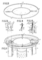
- the exchanger shown in Figure 1 consists of a cylindrical layer of water tubes 5 arranged around a central burner 6 and wrapped in a sealed shell not shown intended to collect the combustion products which are evacuated by a chimney.
- the upper part of the combustion chamber thus delimited is closed by a central disc 2 forming a plug.
- the tubes 5 open into an upper distributor ring 3, a sort of circular "channel", the upper part of which is obstructed by the cover 4 shown in FIG. 2.
- the water must circulate in the tubes of the sheet from a ring lower distributor not shown similar to distributor 3, first ascending in a few neighboring tubes to reach the upper distributor ring, then descending in a few other neighboring tubes and so on. To encourage the water to do these "round trips" between the two rings, it is necessary to partition the distributing rings to delimit watertight sections forming a barrier to the passage of water from a sector to the neighboring sector.
- the removable baffles designated as a whole by the reference 1 perform this function and are held in position by fitting directly into a water tube. They have the shape shown in Figures 3 and 4 and are presented as a T whose vertical leg 10 is intended to be introduced into one of the tubes 5 which serves as a support.
- the horizontal bar 11 of the T is profiled to correspond to the edges of the distributor ring, and topped with a seal 12 of rubber or similar material cut to fit the edges of the circular "channel" forming the distributor ring.
- a lateral border of the joint shows the shape of a point 13 intended to match the border of the central disc 2.
- a recess 14 is provided in the middle of the vertical leg 10, thus making it possible to engage the lower part.
- the baffle 1 forms a barrier to the passage of water between the two immediately adjacent tubes which it isolates from one another. But for this the lower part of the vertical leg 10 must be in abutment against the internal wall of the tube 5. It is for this purpose that the two flanges 15 of the lower part of this vertical leg 10 are provided, flanges whose thickness>. corresponds to that of the tubes 5. These flanges are adjusted so that the baffle 1 inserted in its support is correctly maintained there without risk of vibration.
- the cover 4 When the cover 4 is applied to the top of the distributor ring, the grooves 8 with which it is provided bear against the upper part of the seal 12, promoting sealing and further improving the retention of the baffles.
- the figures represent four baffles delimiting four sectors in the distributor ring 3, but it is obvious that more baffles or fewer baffles could be used without departing from the scope of the invention which also encompasses all other variant embodiments not shown.
Landscapes
- Engineering & Computer Science (AREA)
- Physics & Mathematics (AREA)
- Thermal Sciences (AREA)
- Mechanical Engineering (AREA)
- General Engineering & Computer Science (AREA)
- Chemical & Material Sciences (AREA)
- Combustion & Propulsion (AREA)
- Heat-Exchange Devices With Radiators And Conduit Assemblies (AREA)
- Details Of Fluid Heaters (AREA)
Applications Claiming Priority (2)
| Application Number | Priority Date | Filing Date | Title |
|---|---|---|---|
| FR8111900 | 1981-06-17 | ||
| FR8111900A FR2508157A1 (fr) | 1981-06-17 | 1981-06-17 | Dispositif de cloisonnement a chicanes amovibles pour echangeurs a nappe de tubes d'eau |
Publications (2)
| Publication Number | Publication Date |
|---|---|
| EP0068967A1 true EP0068967A1 (de) | 1983-01-05 |
| EP0068967B1 EP0068967B1 (de) | 1985-01-09 |
Family
ID=9259613
Family Applications (1)
| Application Number | Title | Priority Date | Filing Date |
|---|---|---|---|
| EP82401082A Expired EP0068967B1 (de) | 1981-06-17 | 1982-06-15 | Vorrichtung zum Abschotten mit einsetzbaren Trennwänden für Wärmetauscher mit ringförmig angeordneten Wasserrohren |
Country Status (3)
| Country | Link |
|---|---|
| EP (1) | EP0068967B1 (de) |
| DE (1) | DE3261838D1 (de) |
| FR (1) | FR2508157A1 (de) |
Families Citing this family (1)
| Publication number | Priority date | Publication date | Assignee | Title |
|---|---|---|---|---|
| FR2694388B1 (fr) * | 1992-07-30 | 1994-10-14 | Sdecc | Echangeur de chaleur à nappe de tubes d'eau notamment pour chaudière à condensation. |
Citations (4)
| Publication number | Priority date | Publication date | Assignee | Title |
|---|---|---|---|---|
| GB623561A (en) * | 1945-07-06 | 1949-05-19 | Clifford Mfg Co | Improvements in or relating to a cooler |
| FR2096022A5 (de) * | 1970-06-08 | 1972-02-11 | Miller Avy | |
| FR2261493A1 (de) * | 1974-02-18 | 1975-09-12 | Autobrzdy Jablonec Np | |
| FR2463368A1 (fr) * | 1979-08-09 | 1981-02-20 | Saunier Duval | Corps de chauffe pour chaudieres domestiques de chauffage central a eau chaude par le gaz |
-
1981
- 1981-06-17 FR FR8111900A patent/FR2508157A1/fr active Granted
-
1982
- 1982-06-15 EP EP82401082A patent/EP0068967B1/de not_active Expired
- 1982-06-15 DE DE8282401082T patent/DE3261838D1/de not_active Expired
Patent Citations (4)
| Publication number | Priority date | Publication date | Assignee | Title |
|---|---|---|---|---|
| GB623561A (en) * | 1945-07-06 | 1949-05-19 | Clifford Mfg Co | Improvements in or relating to a cooler |
| FR2096022A5 (de) * | 1970-06-08 | 1972-02-11 | Miller Avy | |
| FR2261493A1 (de) * | 1974-02-18 | 1975-09-12 | Autobrzdy Jablonec Np | |
| FR2463368A1 (fr) * | 1979-08-09 | 1981-02-20 | Saunier Duval | Corps de chauffe pour chaudieres domestiques de chauffage central a eau chaude par le gaz |
Also Published As
| Publication number | Publication date |
|---|---|
| DE3261838D1 (en) | 1985-02-21 |
| EP0068967B1 (de) | 1985-01-09 |
| FR2508157A1 (fr) | 1982-12-24 |
| FR2508157B1 (de) | 1983-12-09 |
Similar Documents
| Publication | Publication Date | Title |
|---|---|---|
| WO2013113684A1 (fr) | Echangeur de chaleur | |
| EP0228918A1 (de) | Verfahren zur Herstellung feuerfest zugestellter Wände für Öfen und Brennkammern und Stein dafür | |
| EP0068967B1 (de) | Vorrichtung zum Abschotten mit einsetzbaren Trennwänden für Wärmetauscher mit ringförmig angeordneten Wasserrohren | |
| EP0779488A1 (de) | Wärmetauscher,insbesondere für Kraftfahrzeuge | |
| EP3384224B1 (de) | Kraftfahrzeugwärmetauscher mit einem ausgleichsbehälter | |
| EP0187108A1 (de) | Behälter, hergestellt aus zwei Behälterhälften, zu gebrauchen als Ausdehnungsgefäss, Ausdehnungsausgleichgefäss und Druckmittelbehälter | |
| FR2463907A1 (fr) | Construction d'un tube recuperateur de chaleur | |
| EP0133604A1 (de) | Kessel mit spiralförmigem Wärmetauscher | |
| EP0267350A1 (de) | Zusammenbauen durch Flansche von Rohrplatten in Wärmetauschern, die Rohrplatten aus massivem Titan enthalten | |
| BE1015282A3 (fr) | Vanne de distribution pour installations de chauffage avec corps en matiere plastique. | |
| FR2566102A1 (fr) | Chaudiere a condensation | |
| EP0581663A1 (de) | Wärmetauscher mit ringförmig angeordneten Wasserrohren, insbesondere für Brennwertkessel | |
| FR2484533A1 (fr) | Vase compensateur pour eau de refroidissement | |
| EP0210899B1 (de) | Entfernbare Abdeckplatte für eine Öffnung, die nur über einen engen Zugang zugänglich ist | |
| BE564280A (de) | ||
| EP0133133B1 (de) | Dampfauslassanschluss für Dampferzeuger | |
| FR2660745A1 (fr) | Four electrique muni de moyens d'etancheite perfectionnes. | |
| EP0898115A1 (de) | Kessel mit externer dichter Wirbelschicht | |
| FR2468852A1 (fr) | Chaudiere, notamment pour installations de chauffage domestique | |
| FR2932249A1 (fr) | Paroi refractaire protegeant le reseau tubulaire des fours, chaudieres et incinerateurs. | |
| FR2680221A1 (fr) | Tuyau isolant pour conduit de cheminee. | |
| FR2738906A1 (fr) | Faisceau de plaques pour un echangeur thermique et echangeur thermique comportant un tel faisceau de plaques | |
| FR2655138A1 (fr) | Procede pour la fabrication d'un echangeur de chaleur. | |
| JPS64495Y2 (de) | ||
| FR2505993A1 (fr) | Dispositif de refroidissement du couvercle d'une chambre de combustion cylindrique |
Legal Events
| Date | Code | Title | Description |
|---|---|---|---|
| PUAI | Public reference made under article 153(3) epc to a published international application that has entered the european phase |
Free format text: ORIGINAL CODE: 0009012 |
|
| AK | Designated contracting states |
Designated state(s): BE CH DE GB IT LI |
|
| 17P | Request for examination filed |
Effective date: 19830617 |
|
| ITF | It: translation for a ep patent filed | ||
| GRAA | (expected) grant |
Free format text: ORIGINAL CODE: 0009210 |
|
| AK | Designated contracting states |
Designated state(s): BE CH DE GB IT LI |
|
| REF | Corresponds to: |
Ref document number: 3261838 Country of ref document: DE Date of ref document: 19850221 |
|
| PLBE | No opposition filed within time limit |
Free format text: ORIGINAL CODE: 0009261 |
|
| STAA | Information on the status of an ep patent application or granted ep patent |
Free format text: STATUS: NO OPPOSITION FILED WITHIN TIME LIMIT |
|
| 26N | No opposition filed | ||
| ITTA | It: last paid annual fee | ||
| PGFP | Annual fee paid to national office [announced via postgrant information from national office to epo] |
Ref country code: GB Payment date: 19940607 Year of fee payment: 13 Ref country code: CH Payment date: 19940607 Year of fee payment: 13 Ref country code: BE Payment date: 19940607 Year of fee payment: 13 |
|
| PGFP | Annual fee paid to national office [announced via postgrant information from national office to epo] |
Ref country code: DE Payment date: 19940709 Year of fee payment: 13 |
|
| PG25 | Lapsed in a contracting state [announced via postgrant information from national office to epo] |
Ref country code: GB Effective date: 19950615 |
|
| PG25 | Lapsed in a contracting state [announced via postgrant information from national office to epo] |
Ref country code: LI Effective date: 19950630 Ref country code: CH Effective date: 19950630 Ref country code: BE Effective date: 19950630 |
|
| BERE | Be: lapsed |
Owner name: SAUNIER DUVAL EAU CHAUDE CHAUFFAGE SDECC - S.A. Effective date: 19950630 |
|
| GBPC | Gb: european patent ceased through non-payment of renewal fee |
Effective date: 19950615 |
|
| REG | Reference to a national code |
Ref country code: CH Ref legal event code: PL |
|
| PG25 | Lapsed in a contracting state [announced via postgrant information from national office to epo] |
Ref country code: DE Effective date: 19960301 |