EP0069045A2 - Socle enfichable pour disjoncteurs de protection multipolaires - Google Patents
Socle enfichable pour disjoncteurs de protection multipolaires Download PDFInfo
- Publication number
- EP0069045A2 EP0069045A2 EP82730071A EP82730071A EP0069045A2 EP 0069045 A2 EP0069045 A2 EP 0069045A2 EP 82730071 A EP82730071 A EP 82730071A EP 82730071 A EP82730071 A EP 82730071A EP 0069045 A2 EP0069045 A2 EP 0069045A2
- Authority
- EP
- European Patent Office
- Prior art keywords
- plug
- base
- contact
- opening
- section
- Prior art date
- Legal status (The legal status is an assumption and is not a legal conclusion. Google has not performed a legal analysis and makes no representation as to the accuracy of the status listed.)
- Granted
Links
Images


Classifications
-
- H—ELECTRICITY
- H02—GENERATION; CONVERSION OR DISTRIBUTION OF ELECTRIC POWER
- H02B—BOARDS, SUBSTATIONS OR SWITCHING ARRANGEMENTS FOR THE SUPPLY OR DISTRIBUTION OF ELECTRIC POWER
- H02B1/00—Frameworks, boards, panels, desks, casings; Details of substations or switching arrangements
- H02B1/015—Boards, panels, desks; Parts thereof or accessories therefor
- H02B1/04—Mounting thereon of switches or of other devices in general, the switch or device having, or being without, casing
- H02B1/056—Mounting on plugboards
-
- H—ELECTRICITY
- H01—ELECTRIC ELEMENTS
- H01H—ELECTRIC SWITCHES; RELAYS; SELECTORS; EMERGENCY PROTECTIVE DEVICES
- H01H11/00—Apparatus or processes specially adapted for the manufacture of electric switches
- H01H11/0006—Apparatus or processes specially adapted for the manufacture of electric switches for converting electric switches
- H01H11/0031—Apparatus or processes specially adapted for the manufacture of electric switches for converting electric switches for allowing different types or orientation of connections to contacts
Definitions
- the invention relates to a plug-in base for multipole low-voltage circuit breakers with an insulating housing and connecting devices located on opposite ends of the insulating housing, the plug-in base having a contact surface for the circuit breaker and the connecting devices of the circuit breaker associated contact units for switch-side contacts and connecting members.
- a socket of this type is e.g. B. is known from US Pat. No. 2,707,761.
- the circuit breaker is a special version with connection devices arranged on the rear. Knife contact pieces attached to the plug base interact with these.
- the invention has for its object to design the plug-in base so that it is easy to manufacture even with a relatively large size with the greatest possible versatility. This is to ensure that the technology of the pluggable circuit breaker for the higher rated currents, eg. B. 630 or 800 A, is economically applicable. For this it is essential to be able to use circuit breakers in the usual design, i. H. those with the usual design of the connection devices for front rail or cable connection.
- the plug-in base can be assembled from two sections which are designed to be joined together in a form-fitting manner, each of which includes part of the support surface and contact units. If the sections are made symmetrical, the size of the tools or molds required for production is reduced by half. The complete plug-in base is then created by joining two identical sections. If, on the other hand, an asymmetrical division is provided, two basic shapes can be used to assemble plug-in bases in three different lengths, thereby creating a plug-in base system for circuit breakers that are of different lengths with the same width.
- the positive connection between the sections of the plug-in base can advantageously be formed by a projection with a tooth-like protruding area and a recess arranged next to it with a corresponding contour.
- the advantage of the tooth-shaped contour is that when the parts are joined together, there is mutual tensioning of the sections, which, with a suitable arrangement of mating surfaces, ensures that a desired total length of the plug base is maintained.
- each section of the plug-in base for each current path has an opening in the longitudinal direction of the plug-in base and another opening at the rear of the plug-in base for the passage of a connecting element.
- the plug-in base is therefore to be provided with either end or rear connections.
- each connection element can have two contact surfaces which are at right angles to one another and are intended to engage between the contact lamellae, and one leg of the connection element can optionally be inserted into one or the other opening.
- each section has a pivotably mounted insulating plate as a cover for the openings serving to engage the plug contact pieces of the circuit breaker in the contact units, and in that the insulating plate and the associated end region have an opening for pulling through a securing element in the folded up position.
- the insulating plate is in normal use of the plug-in base parallel to the support surface and thus forms part of the support surface itself. If the circuit breaker is removed and the plug-in base is to be secured against reinserting the circuit breaker, the insulating plate is folded up and pulled through by a safety device, e.g. B.
- the lock shackle of a padlock held by one of the openings of the insulating plate and a corresponding opening in the associated end portion of the socket.
- the lock bracket prevents the circuit breaker from being inserted.
- the contact units are protected against accidental contact with conductive objects.
- FIG. 1 shows a perspective view of a plug-in base according to the invention with a low-voltage circuit breaker to be fitted.
- FIGS. 2 and 3 show a plug contact piece in two views rotated by 90 °.
- Fig. 4 is a section through one of the contact units contained in the socket.
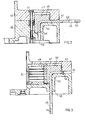
- FIG. 5 and 6 show sections through the end part of a section of the plug-in base along two different cutting lines; in Fig. 5 a connector for the front connection and in Fig. 6 for rear connection is mounted.
- the plug-in base 1 shown in FIG. 1 serves to accommodate a low-voltage circuit breaker 2, which is shown in the raised position. It can be a switch, such as the one used is described in DE-AS 2 817 667.
- connection devices 8 On the face side there are connection devices 8, with which plug-in contact pieces 3 to be explained are connected. These engage in contact units 4, also to be described, one of which is shown in FIG. 1 in the front end region shown partially broken away.
- rail-shaped connecting members 5 extend, to which busbars or cables can be connected.
- the plug-in base 1 consists of two identical sections 6 and 7, which are joined together in a form-fitting manner and which together form a contact surface 9 for the circuit breaker 2.
- each section has a projection 10 or 11 at the end of its flat region forming the bearing surface, the region 12 or 13 of which is located closer to the edge and is shaped in a tooth-like manner.
- the inner flanks 14 and 15 of the projections 10 and 11 are rectilinear in the longitudinal direction of the plug-in base 1 and end in extensions which are provided in order to facilitate the joining of the sections.
- the two sections 6 and 7 engage in one another along a multi-angled line, the projecting region 12 of the projection 10 engaging in a corresponding undercut 16 of the recess 17 which has a projecting region 18.
- a toothing of this type is also present in a symmetrical arrangement on the projection 11 of the section 7 and the recess 19 of the section 6.
- the plug-in base 1 has recesses in contact units 4 for each of the three adjacent current paths.
- the recesses are through one cover 20 shown partially broken closed.
- the cover leaves openings 21 in the longitudinal direction of the plug-in base, which are used for inserting the plug-in contact pieces 3.
- openings for the passage of the connecting members 5 are also left free.
- These have a leg 22, which in the example shown has a bore 23 for a clamping screw.
- a knife contact piece 24, which engages in the contact unit 4, extends transversely to the leg 22.
- connecting member 26 which can be removed with the cover 20 removed in the direction of the curved arrow 25 in FIG. 1
- another connecting piece 26 can be used, which also has a leg 27 as an outer connecting part with a bore 30.
- the connecting member 26 extends with its leg 27 through an opening (not visible in FIG. 1) which opens at the bottom or rear of the plug-in base 1.
- the connector 26 therefore allows the use of the socket for the rear connection of busbars or cables, if so desired.
- the interaction of the connecting member 26 with the contact unit 4 takes place in the same manner as when using the connecting member 5 by means of a knife contact piece 31 molded onto the leg 27 at the top.
- an insulating plate 33 can be inserted in the direction of arrow 34 into a suitable recess through which the placement of the lid 20 is held.
- FIG. 2 shows a section through a differently shaped end region 40 of a plug-in base along an angled cutting line through which one Connecting screw 41 for a cover 42 is made visible.
- a connecting member 43 is angled at right angles and has a longer leg 44 with a bore 45 and a shorter leg 46.
- a knife contact piece 47 which is fixedly connected to the legs or integrally formed therewith, extends over the angular range and accordingly two at a right angle to one another has standing contact areas 48 and 50.
- the end region 40 of the plug-in base is provided with an opening 51 on the front side and an opening 52 on the rear side.
- the leg 44 optionally extends through the opening 51 (FIG. 2) or through the opening 52 (FIG. 3) and is accessible in these positions for the connection of busbars or cables.
- a support shoulder 53 of the end region 40 serves as an abutment against pulling out the connecting member 43 and for aligning the knife contact piece 47 with an associated contact unit 4, the lamellae of which can be seen in FIG. 3.
- An insulating piece 54 closes the opening 51 when the connector 43 for the rear connection is mounted.
- the contact units 4 can be used in the same way for the connecting members 5, 26 and 43.
- the contact unit 4 has a cage-like housing 60, which contains several pairs of contact lamellae 61. Each lamella 61 is supported by a sheet spring 62 against the inner wall of the housing 60. An indentation 63 of each leaf spring 62 and a correspondingly shaped projection 64 of the housing 60 secure against axial displacement of the contact blades.
- the contact lamellae 61 have spherical contact surfaces 65 which interact with the knife contact pieces of the connecting members 5, 26 or 43 or the plug contact pieces 3. More information on the mode of operation of the contact units 4 can be found in DE-PS 1 665 986, so that further explanation can be dispensed with here.
- FIGS. 5 and 6 An example of suitable plug contact pieces 3 is shown in FIGS. 5 and 6.
- the plug contact pieces 3 have a clamping piece 70 which is provided for resting on a clamping plate belonging to each connecting device 8 of the circuit breaker 2 and has a bore 71 for the fastening screw. On both sides of the bore 71 there are concave projections 72, which are used to engage in screw holes in the switch-side clamping plate. This forms an anti-rotation device.
- a knife contact piece 73 is formed in one piece with the clamping piece 70. In the manner already mentioned, this serves to engage between the contact lamellae of the contact units 4.
- each of the end regions of the plug-in base 1 has a transverse web 75 molded onto the cover 20, each of which has two through holes 76 for pulling through the lock shackle of a padlock. If a padlock is attached, the circuit breaker 2 cannot be placed on the socket 1.
- each of the end regions is assigned an insulating plate 77 which is pivotably held in joints and which likewise each have two through openings 80. In the folded up State, the openings 80 correspond to the openings 76 of the webs 75, so that the insulating plate can be held in the folded-up position by a padlock.
- the slots 21, which are provided for the engagement of the plug contact pieces 3, are then covered, so that a risk of contact with live parts of the plug base is avoided.
- the plug-in base can be put together by simply form-fitting assembly of the same parts.
- plug-in bases for larger circuit breakers can be produced with a given tool size. If, contrary to the example described, one chooses an asymmetrical division with otherwise identical design of the interlocking elements, as indicated by dashed lines in FIG. 1 at 45, two different shapes or tools are required, but this gives the possibility of three different ones To be able to produce plug-in bases that differ in length for the same width. In this way, a socket system for circuit breakers of different lengths can be created.
- a positive interlocking of the parts of the socket can also be achieved by other forms of the interlocking parts, of which there are many examples in technology.
- the design described above has proven itself in tests both with regard to the mechanical properties and with regard to its adjustability and is therefore preferred.
- the plug base can be adapted to the line routing in the electrical systems without using special parts.
Landscapes
- Engineering & Computer Science (AREA)
- Power Engineering (AREA)
- Breakers (AREA)
- Connector Housings Or Holding Contact Members (AREA)
- Connecting Device With Holders (AREA)
Applications Claiming Priority (2)
| Application Number | Priority Date | Filing Date | Title |
|---|---|---|---|
| DE19813126306 DE3126306C2 (de) | 1981-06-30 | 1981-06-30 | Stecksockel für mehrpolige Niederspannungs-Schutzschalter |
| DE3126306 | 1981-06-30 |
Publications (3)
| Publication Number | Publication Date |
|---|---|
| EP0069045A2 true EP0069045A2 (fr) | 1983-01-05 |
| EP0069045A3 EP0069045A3 (en) | 1985-10-02 |
| EP0069045B1 EP0069045B1 (fr) | 1987-11-19 |
Family
ID=6136050
Family Applications (1)
| Application Number | Title | Priority Date | Filing Date |
|---|---|---|---|
| EP19820730071 Expired EP0069045B1 (fr) | 1981-06-30 | 1982-06-02 | Socle enfichable pour disjoncteurs de protection multipolaires |
Country Status (3)
| Country | Link |
|---|---|
| EP (1) | EP0069045B1 (fr) |
| JP (1) | JPS587778A (fr) |
| DE (1) | DE3126306C2 (fr) |
Cited By (5)
| Publication number | Priority date | Publication date | Assignee | Title |
|---|---|---|---|---|
| EP0432859A1 (fr) * | 1989-12-15 | 1991-06-19 | Siemens Aktiengesellschaft | Dispositif de contact apte à recevoir des contacts de coupure amovibles d'un appareil de commutation multipolaire |
| FR2738390A1 (fr) * | 1995-08-29 | 1997-03-07 | Kloeckner Moeller Gmbh | Socle a enfichage pour interrupteurs de securite multipolaires basse tension |
| WO2002054432A1 (fr) * | 2000-12-29 | 2002-07-11 | Abb Service Srl | Pied de soutien pour disjoncteur |
| US7280344B2 (en) * | 2005-04-13 | 2007-10-09 | Eaton Corporation | Consolidated circuit breaker support insulator and bus alignment piece |
| CN105023812A (zh) * | 2015-07-13 | 2015-11-04 | 国家电网公司 | 一种单侧式剩余电流动作断路器安装底座 |
Families Citing this family (5)
| Publication number | Priority date | Publication date | Assignee | Title |
|---|---|---|---|---|
| DE3611754A1 (de) * | 1986-04-08 | 1988-01-07 | Bbc Brown Boveri & Cie | Niederspannungs-hochleistungssicherung |
| DE3610451A1 (de) * | 1986-03-27 | 1987-10-01 | Bbc Brown Boveri & Cie | Elektrisches installationsgeraet |
| DE4013311A1 (de) * | 1990-04-26 | 1991-10-31 | Kloeckner Moeller Gmbh | Steckelement fuer die elektrische verbindung, insbesondere in verteileranlagen oder dergleichen |
| DE19632726A1 (de) * | 1996-08-14 | 1998-02-19 | Abb Patent Gmbh | Elektrischer Leitungsschutzschalter |
| JP2023083774A (ja) * | 2021-12-06 | 2023-06-16 | 株式会社オートネットワーク技術研究所 | 端子 |
Family Cites Families (2)
| Publication number | Priority date | Publication date | Assignee | Title |
|---|---|---|---|---|
| US2805294A (en) * | 1955-12-09 | 1957-09-03 | Lota T E Circuit Breaker Compa | Mounting block for circuit breaker |
| DE1665986C3 (de) * | 1967-07-07 | 1973-10-18 | Siemens Ag, 1000 Berlin U. 8000 Muenchen | Kontaktanordnung mit einem Messerkontaktstück und einer Aufnahmevorrichtung |
-
1981
- 1981-06-30 DE DE19813126306 patent/DE3126306C2/de not_active Expired
-
1982
- 1982-06-02 EP EP19820730071 patent/EP0069045B1/fr not_active Expired
- 1982-06-28 JP JP11142082A patent/JPS587778A/ja active Pending
Cited By (5)
| Publication number | Priority date | Publication date | Assignee | Title |
|---|---|---|---|---|
| EP0432859A1 (fr) * | 1989-12-15 | 1991-06-19 | Siemens Aktiengesellschaft | Dispositif de contact apte à recevoir des contacts de coupure amovibles d'un appareil de commutation multipolaire |
| FR2738390A1 (fr) * | 1995-08-29 | 1997-03-07 | Kloeckner Moeller Gmbh | Socle a enfichage pour interrupteurs de securite multipolaires basse tension |
| WO2002054432A1 (fr) * | 2000-12-29 | 2002-07-11 | Abb Service Srl | Pied de soutien pour disjoncteur |
| US7280344B2 (en) * | 2005-04-13 | 2007-10-09 | Eaton Corporation | Consolidated circuit breaker support insulator and bus alignment piece |
| CN105023812A (zh) * | 2015-07-13 | 2015-11-04 | 国家电网公司 | 一种单侧式剩余电流动作断路器安装底座 |
Also Published As
| Publication number | Publication date |
|---|---|
| EP0069045B1 (fr) | 1987-11-19 |
| JPS587778A (ja) | 1983-01-17 |
| DE3126306A1 (de) | 1983-01-13 |
| EP0069045A3 (en) | 1985-10-02 |
| DE3126306C2 (de) | 1983-06-30 |
Similar Documents
| Publication | Publication Date | Title |
|---|---|---|
| EP0899818B1 (fr) | Borne de connexion électrique, notamment pour utilisation sur des plaques de circuits imprimés | |
| EP3734768B1 (fr) | Connecteur enfichable d'un raccord enfichable électrique ainsi que raccord enfichable électrique ainsi formé | |
| DE19835459C2 (de) | Anschlußklemme für elektrische Leiter | |
| DE4433983A1 (de) | Anschlußklemme für elektrische Installationen | |
| DE1465098B2 (de) | Elektrisches verbindungsstueck | |
| DE4102784C2 (de) | Anschlußklemme | |
| DE4016114C2 (de) | Elektrischer Mehrkontakt-Verbinder, der eine geringe Verbindungs- und Trennkraft erfordert | |
| EP0069045B1 (fr) | Socle enfichable pour disjoncteurs de protection multipolaires | |
| DE2825201C2 (de) | Kontaktvorrichtung | |
| DE4431274C2 (de) | Verfahren zum Herstellen eines Elektro-Installationsgerätes sowie Elektro-Installationsgerät | |
| DE3101532C2 (de) | Stecksockel für Niederspannungs-Schutzschalter | |
| DE4018978C2 (de) | Schiebeschalter | |
| DE2920288B2 (de) | Schutzstecker für AnschluBblöcke | |
| DE10045764B4 (de) | Anschlussklemme | |
| DE3030070C1 (de) | Elektrische Anschlussklemme | |
| DE8420661U1 (de) | Elektrischer Hilfsanschluss | |
| DE7613091U1 (de) | Schraubenlose Klemme zur Stromübertragung von elektrischen Leitern | |
| DE10013241B4 (de) | Elektrischer Querbrücker | |
| EP4298695A1 (fr) | Dispositif de connexion électrique | |
| EP1149400A1 (fr) | Appareil electrique a dispositif de raccordement pour le raccordement a un deuxieme appareil electrique | |
| DE29807106U1 (de) | Elektrisches Installationsgerät, insbesondere zur Aufputz-Montage | |
| EP1038109B1 (fr) | Appareil electrique a clip de raccordement et logement de clip de raccordement pour le raccordement a un deuxieme appareil electrique | |
| CH653181A5 (en) | Electrical connecting element | |
| DE19734234C2 (de) | Sicherung mit Kodierung | |
| DE3932346A1 (de) | Elektrischer steckverbinder |
Legal Events
| Date | Code | Title | Description |
|---|---|---|---|
| PUAI | Public reference made under article 153(3) epc to a published international application that has entered the european phase |
Free format text: ORIGINAL CODE: 0009012 |
|
| AK | Designated contracting states |
Designated state(s): FR GB IT |
|
| 17P | Request for examination filed |
Effective date: 19841217 |
|
| PUAL | Search report despatched |
Free format text: ORIGINAL CODE: 0009013 |
|
| AK | Designated contracting states |
Designated state(s): FR GB IT |
|
| 17Q | First examination report despatched |
Effective date: 19870121 |
|
| GRAA | (expected) grant |
Free format text: ORIGINAL CODE: 0009210 |
|
| AK | Designated contracting states |
Kind code of ref document: B1 Designated state(s): FR GB IT |
|
| ET | Fr: translation filed | ||
| ITF | It: translation for a ep patent filed | ||
| GBV | Gb: ep patent (uk) treated as always having been void in accordance with gb section 77(7)/1977 [no translation filed] | ||
| PLBE | No opposition filed within time limit |
Free format text: ORIGINAL CODE: 0009261 |
|
| STAA | Information on the status of an ep patent application or granted ep patent |
Free format text: STATUS: NO OPPOSITION FILED WITHIN TIME LIMIT |
|
| 26N | No opposition filed | ||
| PG25 | Lapsed in a contracting state [announced via postgrant information from national office to epo] |
Ref country code: GB Free format text: LAPSE BECAUSE OF NON-PAYMENT OF DUE FEES Effective date: 19881121 |
|
| ITTA | It: last paid annual fee | ||
| PGFP | Annual fee paid to national office [announced via postgrant information from national office to epo] |
Ref country code: FR Payment date: 19940624 Year of fee payment: 13 |
|
| PG25 | Lapsed in a contracting state [announced via postgrant information from national office to epo] |
Ref country code: FR Effective date: 19960229 |
|
| REG | Reference to a national code |
Ref country code: FR Ref legal event code: ST |