EP0069105B1 - Four industriel modulaire à micro-ondes - Google Patents
Four industriel modulaire à micro-ondes Download PDFInfo
- Publication number
- EP0069105B1 EP0069105B1 EP82870033A EP82870033A EP0069105B1 EP 0069105 B1 EP0069105 B1 EP 0069105B1 EP 82870033 A EP82870033 A EP 82870033A EP 82870033 A EP82870033 A EP 82870033A EP 0069105 B1 EP0069105 B1 EP 0069105B1
- Authority
- EP
- European Patent Office
- Prior art keywords
- microwave
- middle compartment
- openings
- partitions
- compartments
- Prior art date
- Legal status (The legal status is an assumption and is not a legal conclusion. Google has not performed a legal analysis and makes no representation as to the accuracy of the status listed.)
- Expired
Links
- 238000005192 partition Methods 0.000 claims abstract description 8
- 239000002184 metal Substances 0.000 claims abstract description 7
- 238000009434 installation Methods 0.000 description 5
- 238000010276 construction Methods 0.000 description 4
- 238000001816 cooling Methods 0.000 description 2
- 238000001035 drying Methods 0.000 description 2
- 230000000644 propagated effect Effects 0.000 description 2
- 239000004698 Polyethylene Substances 0.000 description 1
- 230000002745 absorbent Effects 0.000 description 1
- 239000002250 absorbent Substances 0.000 description 1
- 230000008878 coupling Effects 0.000 description 1
- 238000010168 coupling process Methods 0.000 description 1
- 238000005859 coupling reaction Methods 0.000 description 1
- 238000010438 heat treatment Methods 0.000 description 1
- 239000012212 insulator Substances 0.000 description 1
- 230000003993 interaction Effects 0.000 description 1
- 239000000463 material Substances 0.000 description 1
- -1 polyethylene Polymers 0.000 description 1
- 229920000573 polyethylene Polymers 0.000 description 1
Images

Classifications
-
- H—ELECTRICITY
- H05—ELECTRIC TECHNIQUES NOT OTHERWISE PROVIDED FOR
- H05B—ELECTRIC HEATING; ELECTRIC LIGHT SOURCES NOT OTHERWISE PROVIDED FOR; CIRCUIT ARRANGEMENTS FOR ELECTRIC LIGHT SOURCES, IN GENERAL
- H05B6/00—Heating by electric, magnetic or electromagnetic fields
- H05B6/64—Heating using microwaves
- H05B6/78—Arrangements for continuous movement of material
-
- H—ELECTRICITY
- H05—ELECTRIC TECHNIQUES NOT OTHERWISE PROVIDED FOR
- H05B—ELECTRIC HEATING; ELECTRIC LIGHT SOURCES NOT OTHERWISE PROVIDED FOR; CIRCUIT ARRANGEMENTS FOR ELECTRIC LIGHT SOURCES, IN GENERAL
- H05B2206/00—Aspects relating to heating by electric, magnetic, or electromagnetic fields covered by group H05B6/00
- H05B2206/04—Heating using microwaves
- H05B2206/046—Microwave drying of wood, ink, food, ceramic, sintering of ceramic, clothes, hair
Definitions
- the present invention relates to a modular industrial microwave oven for drying or heat treatment of products by microwave.
- the invention relates to a continuously operating device which, by its modular structure, is suitable for most industrial energy uses ranging from 10 to several hundred kilowatts.
- a microwave oven which is characterized by at least one module consisting of a metal box divided into three compartments by partitions having openings, by several microwave generators, for example 25 at 50 low power magnetrons, these generators being arranged in the external compartments such that the hot air is propagated directly in the median compartment by said openings in the partitions, the median compartment constituting the applicator oven proper.
- Several waveguides are mounted on the metal box with radiators so that the maximum amount of microwave energy is applied in the middle compartment.
- FIG. 1 schematically illustrates a common microwave installation
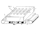
- fig. 2 is a perspective view of an embodiment of a microwave module according to the invention
- fig. 3 is a schematic sectional view of the embodiment of FIG. 2.
- fig. 1 shows the construction of a usual industrial microwave installation.
- the reference 1 designates a microwave generator which is connected by an isolator 2 and a passive transfer part 3, for example a circulator, to a microwave applicator 4 in which the product to be treated is placed.
- Figs. 2 and 3 show a modular unit according to the invention.
- This unit 10 essentially comprises a metal box 1 divided into three compartments 11, 12 and 13 by partitions 14 and 15.
- the external compartments 11 and 13 contain the power units including a group of microwave or magnetron generators 4 and the power transformers 8; the middle compartment 12 forms the actual applicator in which the product is treated.
- the partitions 14 and 15 between the compartments have openings, 16 and 17 respectively.
- the magnetrons 4 are arranged relative to these openings 16 and 17 in such a way that the hot air coming from the cooling of the magnetrons is propagated directly in the applicator compartment 12.
- the openings 16 and 17 are each provided with a screen 18.
- the microwave energy of the magnetrons is applied in the compartment 12 by means of radiators 3 which are uniformly distributed along each waveguide 2.
- the location of the waveguides 2 as well as that of the radiators 3 are chosen so that the coupling between the different magnetrons can be done without losses. In this way, not only is the presence of insulators and circulators avoided, but also the efficiency is significantly increased.
- the position and distribution of the radiators 3 above the middle compartment 12 are determined in such a way that the interaction between the magnetrons is practically eliminated.
- a 36 kW microwave oven project (18 x 2 1 kW magnetrons) working at the frequency of 2450 MHz and used for drying plasticized paper, has seventy-two radiators spread over ten - eight rows of four with a spacing of approximately twenty-five centimeters between rows, the radiators in each row being spaced from each other by approximately fifteen centimeters.
- the external compartments 11 and 13 are put under a variable air pressure by separate fans 9. Thus not only the cooling heat of the magnetrons but also that of the transformers are used in the enclosure of the compartment 12.
- the evacuation is via outputs 5.
- a conveyor belt 6 made of a flexible and non-absorbent material, for example polyethylene, which passes through the middle compartment 12 for transporting the product to be treated.
- a flexible and non-absorbent material for example polyethylene
Landscapes
- Physics & Mathematics (AREA)
- Electromagnetism (AREA)
- Constitution Of High-Frequency Heating (AREA)
- Furnace Details (AREA)
- Transition And Organic Metals Composition Catalysts For Addition Polymerization (AREA)
- Arc-Extinguishing Devices That Are Switches (AREA)
- Compositions Of Oxide Ceramics (AREA)
- Inorganic Insulating Materials (AREA)
- Control Of High-Frequency Heating Circuits (AREA)
Description
- La présente invention concerne un four industriel modulaire à micro-ondes destiné au séchage ou au traitement thermique de produits par micro-ondes. L'invention vise un appareil à fonctionnement continu qui par sa structure modulaire, convient pour la plupart des utilisations d'énergie industrielles allant de 10 à plusieurs centaines de kilowatts.
- Le traitement de produits par micro-ondes est certes déjà connu. A cet effet, on utilise habituellement une installation (fig. 1) comprenant un générateur micro-ondes et un applicateur de micro-ondes dans lequel est traité le produit, le générateur et l'applicateur étant couplés entre eux par l'intermédiaire d'un isolateur et de pièces de transfert passives. Une telle installation a les inconvénients suivants :
- a) elle utilise de coûteux générateurs de grande puissance, qui doivent être protégés au moyen de circulateurs micro-ondes très coûteux,
- b) le rendement est généralement très bas par suite de l'énergie micro-ondes renvoyée. L'invention a pour but un four qui présente les particularités suivantes :
- a) un rendement élevé jusqu'à 80 % à partir du réseau de distribution d'énergie,
- b) un fonctionnement continu et discontinu,
- c) une précision élevée et une grande souplesse de réglage d'énergie,
- d) une construction modulaire,
- e) une économie de construction.
- Ce but est atteint selon l'invention par un four à micro-ondes qui se caractérise par au moins un module constitué d'un caisson métallique divisé en trois compartiments par des cloisons présentant des ouvertures, par plusieurs générateurs micro-ondes, par exemple 25 à 50 magnétrons de faible puissance, ces générateurs étant disposés dans les compartiments extérieurs de telle manière que l'air chaud se propage directement dans le compartiment médian par lesdites ouvertures dans les cloisons, le compartiment médian constituant le four applicateur proprement dit. Plusieurs guides d'ondes sont montés sur le caisson métallique avec des radiateurs en sorte que le maximum d'énergie micro-ondes soit appliqué dans le compartiment médian.
- D'autres particularités du four selon l'invention apparaîtront à la lecture de l'exposé qui suit avec référence aux dessins ci-annexés dans lesquels : la fig. 1 illustre schématiquement une installation micro-ondes courante ; la fig. 2 est une vue en perspective d'un mode d'exécution d'un module à micro-ondes selon l'invention ; la fig. 3 est une vue en coupe schématique du mode d'exécution de la fig. 2.
- Pour illustrer l'état de la technique, la fig. 1 montre la constitution d'une installation industrielle usuelle à micro-ondes. La référence 1 désigne un générateur micro-ondes qui se trouve relié par un isolateur 2 et une pièce de transfert passive 3, par exemple un circulateur, à un applicateur de micro-ondes 4 dans lequel se place le produit à traiter.
- Les fig. 2 et 3 montrent une unité modulaire selon l'invention. Cette unité 10 comporte essentiellement un caisson métallique 1 divisé en trois compartiments 11, 12 et 13 par des cloisons 14 et 15. Les compartiments extérieurs 11 et 13 contiennent les unités de puissance dont un groupe de générateurs de micro-ondes ou magnétrons 4 et les transformateurs d'alimentation 8 ; le compartiment médian 12 forme l'applicateur proprement dit dans lequel est traité le produit. Les cloisons 14 et 15 entre les compartiments présentent des ouvertures, 16 et 17 respectivement.
- Les magnétrons 4 sont disposés par rapport à ces ouvertures 16 et 17 de telle manière que l'air chaud provenant du refroidissement des magnétrons, se propage directement dans le compartiment applicateur 12. Les ouvertures 16 et 17 sont chacune garnies d'un grillage 18.
- Au-dessus du caisson 1 sont montés un certain nombre de guides d'ondes 2. L'énergie micro-ondes des magnétrons se trouve appliquée dans le compartiment 12 au moyen de radiateurs 3 qui sont uniformément répartis le long de chaque guide d'ondes 2. L'emplacement des guides d'ondes 2 ainsi que celui des radiateurs 3 sont choisis en sorte que le couplage entre les différents magnétrons puisse se faire sans pertes. De cette façon, non seulement on évite la présence d'isolateurs et de circulateurs, mais également le rendement se trouve-t-il sensiblement augmenté. La position et la répartition des radiateurs 3 au-dessus du compartiment médian 12 sont déterminées de telle façon que l'interaction entre les magnétrons soit pratiquement éliminée.
- A titre d'exemple, dans un projet de four à micro-ondes de 36 kW (18 x 2 magnétrons de 1 kW) travaillant à la fréquence de 2450 MHz et servant au séchage de papier plastifié, comporte soixante-douze radiateurs répartis sur dix-huit rangées de quatre avec un écartement d'environ vingt-cinq centimètres entre rangées, les radiateurs de chaque rangée étant écartés l'un de l'autre d'environ quinze centimètres.
- Les compartiments extérieurs 11 et 13 sont mis sous une pression d'air variable par des ventilateurs séparés 9. Ainsi non seulement la chaleur de refroidissement des magnétrons mais également celle des transformateurs se trouvent-elles utilisées dans l'enceinte du compartiment 12. L'évacuation se fait par les sorties 5.
- Dans la forme de réalisation illustrée sur les dessins ci-annexés on voit encore une bande transporteuse 6 constituée d'un matériau souple et non absorbant, par exemple du polyéthylène, qui traverse le compartiment médian 12 pour le transport du produit à traiter. Ainsi un fonctionnement continu se trouve-t-il assuré.
- La structure modulaire décrite dans ce qui précède permet de réaliser des installations de n'importe quelle puissance en juxtaposant simplement le nombre voulu de modules selon l'invention.
Claims (2)
Priority Applications (1)
| Application Number | Priority Date | Filing Date | Title |
|---|---|---|---|
| AT82870033T ATE19334T1 (de) | 1981-06-29 | 1982-06-18 | Modularer industrieller mikrowellenofen. |
Applications Claiming Priority (2)
| Application Number | Priority Date | Filing Date | Title |
|---|---|---|---|
| NL8103118 | 1981-06-29 | ||
| NL8103118A NL8103118A (nl) | 1981-06-29 | 1981-06-29 | Modulaire industriele mikrogolfoven voor thermische behandeling van stoffen. |
Publications (2)
| Publication Number | Publication Date |
|---|---|
| EP0069105A1 EP0069105A1 (fr) | 1983-01-05 |
| EP0069105B1 true EP0069105B1 (fr) | 1986-04-16 |
Family
ID=19837709
Family Applications (1)
| Application Number | Title | Priority Date | Filing Date |
|---|---|---|---|
| EP82870033A Expired EP0069105B1 (fr) | 1981-06-29 | 1982-06-18 | Four industriel modulaire à micro-ondes |
Country Status (9)
| Country | Link |
|---|---|
| EP (1) | EP0069105B1 (fr) |
| AT (1) | ATE19334T1 (fr) |
| CA (1) | CA1190605A (fr) |
| DE (1) | DE3270591D1 (fr) |
| ES (1) | ES513491A0 (fr) |
| GR (1) | GR75434B (fr) |
| IE (1) | IE52949B1 (fr) |
| NL (1) | NL8103118A (fr) |
| PT (1) | PT75071B (fr) |
Families Citing this family (5)
| Publication number | Priority date | Publication date | Assignee | Title |
|---|---|---|---|---|
| AT390734B (de) * | 1987-04-14 | 1990-06-25 | Katschnig Helmut | Vorrichtung zum abtoeten bzw. inaktivieren von eiweiss- bzw. nukleinsaeurehaeltigen organismen |
| DE3926363A1 (de) * | 1989-08-10 | 1991-02-14 | Reinhard Schulze | Verfahren und einrichtung zur waermebehandlung von gemischen organischer substanzen und zugehoerige anwendung |
| DE4001220A1 (de) * | 1990-01-17 | 1991-07-18 | Reinhard Schulze | Mikrowellenkammer und zugehoerige magnetroneinheit |
| FR2885003B1 (fr) * | 2005-04-22 | 2007-06-29 | Premark Feg Llc | Four a micro-ondes avec conduit d'air de refroidissement |
| ES2342958B2 (es) * | 2008-09-03 | 2011-07-04 | Emite Ingenieria Slne | Analizador de multiples entradas y multiples salidas. |
Family Cites Families (9)
| Publication number | Priority date | Publication date | Assignee | Title |
|---|---|---|---|---|
| US3127495A (en) * | 1961-09-05 | 1964-03-31 | Studebaker Corp | Microwave oven |
| CH426051A (de) * | 1965-10-25 | 1966-12-15 | Patelhold Patentverwertung | Mikrowellenbehandlungstunnel |
| FR2076405A5 (fr) * | 1970-01-14 | 1971-10-15 | Materiel Telephonique | |
| US3654417A (en) * | 1970-10-30 | 1972-04-04 | Litton Precision Prod Inc | Microwave oven including air flow system |
| JPS52587B2 (fr) * | 1972-04-11 | 1977-01-08 | ||
| FR2227230A1 (en) * | 1973-04-27 | 1974-11-22 | Mauviel Michel | Drying of sludge and town refuse - is effected by high frequency waves without incineration |
| FR2327700A1 (fr) * | 1975-10-09 | 1977-05-06 | Meisel Nicolas | Four tunnel a micro-ondes pour le traitement en continu de produits alimentaires |
| FR2428369A1 (fr) * | 1978-06-08 | 1980-01-04 | Cim Lambda Int Sarl | Procede et dispositif pour le traitement thermique d'objets par emission de micro-ondes |
| GB2054330A (en) * | 1979-07-17 | 1981-02-11 | Unicorn Ind Ltd | Microwave heat treatment apparatus |
-
1981
- 1981-06-29 NL NL8103118A patent/NL8103118A/nl not_active Application Discontinuation
-
1982
- 1982-06-17 PT PT75071A patent/PT75071B/pt unknown
- 1982-06-18 AT AT82870033T patent/ATE19334T1/de not_active IP Right Cessation
- 1982-06-18 EP EP82870033A patent/EP0069105B1/fr not_active Expired
- 1982-06-18 DE DE8282870033T patent/DE3270591D1/de not_active Expired
- 1982-06-23 GR GR68547A patent/GR75434B/el unknown
- 1982-06-25 CA CA000406026A patent/CA1190605A/fr not_active Expired
- 1982-06-25 ES ES513491A patent/ES513491A0/es active Granted
- 1982-06-28 IE IE1545/82A patent/IE52949B1/en unknown
Also Published As
| Publication number | Publication date |
|---|---|
| PT75071A (en) | 1982-07-01 |
| PT75071B (en) | 1984-01-04 |
| IE821545L (en) | 1982-12-29 |
| IE52949B1 (en) | 1988-04-13 |
| GR75434B (fr) | 1984-07-17 |
| CA1190605A (fr) | 1985-07-16 |
| DE3270591D1 (en) | 1986-05-22 |
| ES8305176A1 (es) | 1983-03-16 |
| EP0069105A1 (fr) | 1983-01-05 |
| ES513491A0 (es) | 1983-03-16 |
| ATE19334T1 (de) | 1986-05-15 |
| NL8103118A (nl) | 1983-01-17 |
Similar Documents
| Publication | Publication Date | Title |
|---|---|---|
| US4474498A (en) | Multiple-pass impingement heating and cooling device | |
| US1814897A (en) | Apparatus for utilizing solar heat | |
| AU556134B2 (en) | Heating photovoltaic cell substrate | |
| EP1212575B1 (fr) | Appareil et procédé de séchage de céramique par micro-ondes, en continu | |
| KR880012790A (ko) | 부품 운송과 코팅방법 및 장치 | |
| US4622448A (en) | Microwave vacuum dryer apparatus | |
| US12013173B2 (en) | Refrigerating and freezing device | |
| US6005235A (en) | Cooling apparatus for a microwave oven having lighting lamps | |
| US4471192A (en) | Microwave heating apparatus | |
| EP0069105A1 (fr) | Four industriel modulaire à micro-ondes | |
| KR100288933B1 (ko) | 광파히터를 사용하는 전자레인지의 히터커버 | |
| US3027442A (en) | High-frequency furnaces | |
| WO1985005545A1 (fr) | Four a alimentation continue | |
| US10912317B2 (en) | Thermal processing apparatus | |
| US20220128297A1 (en) | Refrigerating and freezing device | |
| US3688068A (en) | Continuous microwave heating or cooking system and method | |
| US3239643A (en) | Ultra-high frequency heating system | |
| US5660543A (en) | Method and apparatus for enhanced convection brazing of aluminum assemblies | |
| KR20130020882A (ko) | 기판의 열 처리 장치 | |
| KR102143093B1 (ko) | 전자파 공급장치 | |
| FR2650310A1 (fr) | Installation de traitement thermique de fils textiles en continu | |
| EP0467898B2 (fr) | Four a vide | |
| GB2108260A (en) | Space heating systems | |
| RU2757925C2 (ru) | Реактор для проксимального и перпендикулярного излучения электромагнитных волн на тонком слое жидкости | |
| JPS56117050A (en) | Manufacture of solar heat selective absorbing surface |
Legal Events
| Date | Code | Title | Description |
|---|---|---|---|
| PUAI | Public reference made under article 153(3) epc to a published international application that has entered the european phase |
Free format text: ORIGINAL CODE: 0009012 |
|
| AK | Designated contracting states |
Designated state(s): AT BE CH DE FR GB IT LI LU SE |
|
| 17P | Request for examination filed |
Effective date: 19830615 |
|
| ITF | It: translation for a ep patent filed | ||
| GRAA | (expected) grant |
Free format text: ORIGINAL CODE: 0009210 |
|
| AK | Designated contracting states |
Kind code of ref document: B1 Designated state(s): AT BE CH DE FR GB IT LI LU SE |
|
| REF | Corresponds to: |
Ref document number: 19334 Country of ref document: AT Date of ref document: 19860515 Kind code of ref document: T |
|
| REF | Corresponds to: |
Ref document number: 3270591 Country of ref document: DE Date of ref document: 19860522 |
|
| PG25 | Lapsed in a contracting state [announced via postgrant information from national office to epo] |
Ref country code: LU Free format text: LAPSE BECAUSE OF NON-PAYMENT OF DUE FEES Effective date: 19860630 |
|
| PGFP | Annual fee paid to national office [announced via postgrant information from national office to epo] |
Ref country code: AT Payment date: 19860812 Year of fee payment: 5 |
|
| PLBE | No opposition filed within time limit |
Free format text: ORIGINAL CODE: 0009261 |
|
| STAA | Information on the status of an ep patent application or granted ep patent |
Free format text: STATUS: NO OPPOSITION FILED WITHIN TIME LIMIT |
|
| 26N | No opposition filed | ||
| PG25 | Lapsed in a contracting state [announced via postgrant information from national office to epo] |
Ref country code: GB Effective date: 19890618 Ref country code: AT Effective date: 19890618 |
|
| PG25 | Lapsed in a contracting state [announced via postgrant information from national office to epo] |
Ref country code: SE Effective date: 19890619 |
|
| PG25 | Lapsed in a contracting state [announced via postgrant information from national office to epo] |
Ref country code: LI Effective date: 19890630 Ref country code: CH Effective date: 19890630 Ref country code: BE Effective date: 19890630 |
|
| PGFP | Annual fee paid to national office [announced via postgrant information from national office to epo] |
Ref country code: FR Payment date: 19890630 Year of fee payment: 8 |
|
| PGFP | Annual fee paid to national office [announced via postgrant information from national office to epo] |
Ref country code: DE Payment date: 19890704 Year of fee payment: 8 |
|
| BERE | Be: lapsed |
Owner name: DE BELGISCHE STAAT L'ETAT BELGE REPRESENTE PAR LE Effective date: 19890630 |
|
| GBPC | Gb: european patent ceased through non-payment of renewal fee | ||
| REG | Reference to a national code |
Ref country code: CH Ref legal event code: PL |
|
| PG25 | Lapsed in a contracting state [announced via postgrant information from national office to epo] |
Ref country code: FR Effective date: 19910228 |
|
| PG25 | Lapsed in a contracting state [announced via postgrant information from national office to epo] |
Ref country code: DE Effective date: 19910301 |
|
| REG | Reference to a national code |
Ref country code: FR Ref legal event code: ST |
|
| EUG | Se: european patent has lapsed |
Ref document number: 82870033.6 Effective date: 19900412 |