EP0069171B1 - Dispositif de pilotage par variation de la polarité aux bornes d'un onduleur alimentant une machine asynchrone - Google Patents
Dispositif de pilotage par variation de la polarité aux bornes d'un onduleur alimentant une machine asynchrone Download PDFInfo
- Publication number
- EP0069171B1 EP0069171B1 EP81200721A EP81200721A EP0069171B1 EP 0069171 B1 EP0069171 B1 EP 0069171B1 EP 81200721 A EP81200721 A EP 81200721A EP 81200721 A EP81200721 A EP 81200721A EP 0069171 B1 EP0069171 B1 EP 0069171B1
- Authority
- EP
- European Patent Office
- Prior art keywords
- circuit
- inverter
- regime
- value
- transitional
- Prior art date
- Legal status (The legal status is an assumption and is not a legal conclusion. Google has not performed a legal analysis and makes no representation as to the accuracy of the status listed.)
- Expired
Links
- 230000008859 change Effects 0.000 title claims abstract description 10
- 238000009499 grossing Methods 0.000 claims abstract description 46
- 230000010349 pulsation Effects 0.000 claims abstract description 35
- 230000007547 defect Effects 0.000 claims abstract 2
- 230000000737 periodic effect Effects 0.000 claims abstract 2
- 230000008929 regeneration Effects 0.000 claims abstract 2
- 238000011069 regeneration method Methods 0.000 claims abstract 2
- 230000002035 prolonged effect Effects 0.000 claims description 11
- 230000001105 regulatory effect Effects 0.000 claims description 11
- 239000003990 capacitor Substances 0.000 claims description 7
- 230000002159 abnormal effect Effects 0.000 claims 1
- 238000010304 firing Methods 0.000 claims 1
- 230000003068 static effect Effects 0.000 claims 1
- 238000012163 sequencing technique Methods 0.000 description 27
- 230000007704 transition Effects 0.000 description 21
- 230000001052 transient effect Effects 0.000 description 19
- 238000007493 shaping process Methods 0.000 description 18
- 238000000034 method Methods 0.000 description 8
- 238000010586 diagram Methods 0.000 description 7
- 238000009434 installation Methods 0.000 description 7
- 238000005259 measurement Methods 0.000 description 7
- 230000001172 regenerating effect Effects 0.000 description 7
- 230000008033 biological extinction Effects 0.000 description 6
- 230000008569 process Effects 0.000 description 6
- 230000002194 synthesizing effect Effects 0.000 description 6
- 230000000903 blocking effect Effects 0.000 description 5
- 230000002747 voluntary effect Effects 0.000 description 5
- 230000004907 flux Effects 0.000 description 4
- 238000011084 recovery Methods 0.000 description 4
- 230000001133 acceleration Effects 0.000 description 3
- 230000001276 controlling effect Effects 0.000 description 3
- 230000000750 progressive effect Effects 0.000 description 3
- 230000009467 reduction Effects 0.000 description 3
- 230000033228 biological regulation Effects 0.000 description 2
- 230000008034 disappearance Effects 0.000 description 2
- 230000002401 inhibitory effect Effects 0.000 description 2
- 230000002441 reversible effect Effects 0.000 description 2
- 238000007664 blowing Methods 0.000 description 1
- 230000015556 catabolic process Effects 0.000 description 1
- 238000006243 chemical reaction Methods 0.000 description 1
- 230000006378 damage Effects 0.000 description 1
- 230000006698 induction Effects 0.000 description 1
- 230000001939 inductive effect Effects 0.000 description 1
- 238000007689 inspection Methods 0.000 description 1
- 238000012423 maintenance Methods 0.000 description 1
- 230000001681 protective effect Effects 0.000 description 1
- 230000008439 repair process Effects 0.000 description 1
- 230000001360 synchronised effect Effects 0.000 description 1
- 230000017105 transposition Effects 0.000 description 1
- 238000011144 upstream manufacturing Methods 0.000 description 1
Images






Classifications
-
- B—PERFORMING OPERATIONS; TRANSPORTING
- B60—VEHICLES IN GENERAL
- B60L—PROPULSION OF ELECTRICALLY-PROPELLED VEHICLES; SUPPLYING ELECTRIC POWER FOR AUXILIARY EQUIPMENT OF ELECTRICALLY-PROPELLED VEHICLES; ELECTRODYNAMIC BRAKE SYSTEMS FOR VEHICLES IN GENERAL; MAGNETIC SUSPENSION OR LEVITATION FOR VEHICLES; MONITORING OPERATING VARIABLES OF ELECTRICALLY-PROPELLED VEHICLES; ELECTRIC SAFETY DEVICES FOR ELECTRICALLY-PROPELLED VEHICLES
- B60L7/00—Electrodynamic brake systems for vehicles in general
- B60L7/003—Dynamic electric braking by short circuiting the motor
-
- B—PERFORMING OPERATIONS; TRANSPORTING
- B60—VEHICLES IN GENERAL
- B60L—PROPULSION OF ELECTRICALLY-PROPELLED VEHICLES; SUPPLYING ELECTRIC POWER FOR AUXILIARY EQUIPMENT OF ELECTRICALLY-PROPELLED VEHICLES; ELECTRODYNAMIC BRAKE SYSTEMS FOR VEHICLES IN GENERAL; MAGNETIC SUSPENSION OR LEVITATION FOR VEHICLES; MONITORING OPERATING VARIABLES OF ELECTRICALLY-PROPELLED VEHICLES; ELECTRIC SAFETY DEVICES FOR ELECTRICALLY-PROPELLED VEHICLES
- B60L7/00—Electrodynamic brake systems for vehicles in general
- B60L7/22—Dynamic electric resistor braking, combined with dynamic electric regenerative braking
-
- H—ELECTRICITY
- H02—GENERATION; CONVERSION OR DISTRIBUTION OF ELECTRIC POWER
- H02P—CONTROL OR REGULATION OF ELECTRIC MOTORS, ELECTRIC GENERATORS OR DYNAMO-ELECTRIC CONVERTERS; CONTROLLING TRANSFORMERS, REACTORS OR CHOKE COILS
- H02P23/00—Arrangements or methods for the control of AC motors characterised by a control method other than vector control
- H02P23/06—Controlling the motor in four quadrants
- H02P23/07—Polyphase or monophase asynchronous induction motors
-
- H—ELECTRICITY
- H02—GENERATION; CONVERSION OR DISTRIBUTION OF ELECTRIC POWER
- H02P—CONTROL OR REGULATION OF ELECTRIC MOTORS, ELECTRIC GENERATORS OR DYNAMO-ELECTRIC CONVERTERS; CONTROLLING TRANSFORMERS, REACTORS OR CHOKE COILS
- H02P3/00—Arrangements for stopping or slowing electric motors, generators, or dynamo-electric converters
- H02P3/06—Arrangements for stopping or slowing electric motors, generators, or dynamo-electric converters for stopping or slowing an individual dynamo-electric motor or dynamo-electric converter
- H02P3/18—Arrangements for stopping or slowing electric motors, generators, or dynamo-electric converters for stopping or slowing an individual dynamo-electric motor or dynamo-electric converter for stopping or slowing an AC motor
-
- B—PERFORMING OPERATIONS; TRANSPORTING
- B60—VEHICLES IN GENERAL
- B60L—PROPULSION OF ELECTRICALLY-PROPELLED VEHICLES; SUPPLYING ELECTRIC POWER FOR AUXILIARY EQUIPMENT OF ELECTRICALLY-PROPELLED VEHICLES; ELECTRODYNAMIC BRAKE SYSTEMS FOR VEHICLES IN GENERAL; MAGNETIC SUSPENSION OR LEVITATION FOR VEHICLES; MONITORING OPERATING VARIABLES OF ELECTRICALLY-PROPELLED VEHICLES; ELECTRIC SAFETY DEVICES FOR ELECTRICALLY-PROPELLED VEHICLES
- B60L2200/00—Type of vehicles
- B60L2200/26—Rail vehicles
-
- Y—GENERAL TAGGING OF NEW TECHNOLOGICAL DEVELOPMENTS; GENERAL TAGGING OF CROSS-SECTIONAL TECHNOLOGIES SPANNING OVER SEVERAL SECTIONS OF THE IPC; TECHNICAL SUBJECTS COVERED BY FORMER USPC CROSS-REFERENCE ART COLLECTIONS [XRACs] AND DIGESTS
- Y02—TECHNOLOGIES OR APPLICATIONS FOR MITIGATION OR ADAPTATION AGAINST CLIMATE CHANGE
- Y02T—CLIMATE CHANGE MITIGATION TECHNOLOGIES RELATED TO TRANSPORTATION
- Y02T10/00—Road transport of goods or passengers
- Y02T10/60—Other road transportation technologies with climate change mitigation effect
- Y02T10/64—Electric machine technologies in electromobility
Definitions
- the invention relates to a device for controlling the polarity at the terminals of an inverter supplying an asynchronous machine. As soon as a torque inversion is requested, this device imposes a specific configuration for the transient phase to isolate the chopper from the DC voltage source and reverse the polarities at the terminals of the inverter by alternative variations of the sign affecting the modular value of rotor pulsation by a current regulating element.
- the transition from a traction configuration to a braking configuration is carried out, by using contactors switched only in the absence of current, the supply of the machine is first interrupted. direct current by blocking the choppers during contactor switching. The machine is then re-energized using a premagnetization device until it is again able to maintain its own flow.
- Another means used is to change the configuration of the circuit without waiting for the cancellation of direct current. This operation is made delicate by the use of fast contactors often generating overvoltages at the terminals of the various electronic components. In addition, these components require frequent inspections and maintenance to maintain an acceptable level of reliability.
- the present invention refers to a control device according to the preamble of claim 1 as it is known from document FR-A-2 333 312.
- This document describes a control circuit provided, in particular, for rheostatic braking of '' an alternating current motor, supplied from a current inverter, by controlling the power dissipated in the braking resistor in order to ensure the development of a constant torque during the braking operation.
- the opening and closing of the switches are simply coordinated with an inverter, which makes it possible to pass from the traction position to the braking position. As a result, switches may degrade more quickly and should be inspected more frequently.
- the invention as proposed in claim 1 eliminates the aforementioned drawbacks.
- control device which includes a sequence of sequences allowing an appropriate circuit to disconnect the DC voltage source and take the configuration suitable for braking while, by electronic control, the polarities at the terminals of the inverter are reversed. to maintain the circulating current in the smoothing inductor, mounted between the chopper and the inverter, at a predetermined average level.
- the operator modifies at will the traction torque requested from the asynchronous motor 6 by acting on the station 8 which transmits the information to the station 9 to impose the operating point of the machine.
- the sign + affecting ro 2 depends on the sign of the torque requested from the shaping element 8 from the control station.
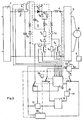
- Figure 2 shows the first sequence of the transition phase.
- the operator wishes to activate the dynamic brake by actuating the control lever, he acts on the shaping element 8 which, upon reversing the sign of the desired electromagnetic torque, puts the installation in transient phase.
- control circuits will intervene simultaneously to, on the one hand, disconnect the chopper 3 from the DC voltage source, the rectifier 1, and connect the chopper 3 in parallel to the rheostatic braking resistor Rfr via a diode braking Dfr and, on the other hand, reverse the polarities across the terminals of the inverter to circulate a current in the smoothing inductor 4 capable of maintaining a sufficient flux in the asynchronous machine 6.
- the sequencing element 12 imposes on the control device the configuration specific to the transient phase by switching the three switches Cm ,, Cm 2 , Cm 3 .
- the ignition of the auxiliary thyristor Th 2 causes the closing of the extinction circuit C 1 L 1 and the establishment of a current which causes the extinction of the main thyristor Th ,.
- the contactor K 1 is opened to isolate the chopper 3 from the DC voltage source, the rectifier 1.
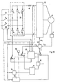
- Figure 3 corresponds to the second sequence of the transient phase. It represents the installation from the moment when, by switching on the main thyristor Th 1 again while inhibiting the control of the extinction circuit, the current is offered the possibility of passing through the braking diode Df r . Contactors K 2 and K 3 can therefore be opened simultaneously
- FIG. 4 shows the installation in braking phase. This phase begins as soon as the contactors K 2 and K 3 are open. From this moment, the extinction circuit of the chopper 3 controlled by the current regulator 11 in the smoothing reactor 4 is returned to service. The switches Cm ,, Cm 2 , Cm 3 are toggled to return to their normal position and the chopper works again normally, that is to say that by successive blockings and unblocks of the main thyristor Th i , the current flow is alternated either in the braking diode Df r , i.e. in the rheostatic braking resistor R f r to thus have controlled rheostatic braking.
- ⁇ 2 is, in the simplest case, maintained at a fixed value by the element with constant reference 16.
- the sign of ⁇ 2 is made alternately positive and negative according to the value of the current measured in the choke of smoothing 4 and compared for example in the current regulating element 10 used in transient period with two predetermined thresholds.
- the inverter 5 disconnected from the DC voltage source, the rectifier 1, is controlled by the synthesizer element 13 which applies a stator pulsation instruction ⁇ 1 , alternatively higher or lower than the speed measurement Pro, recorded by the speed sensor 7.
- the rotor pulsation ⁇ 2 can be adjusted in two different ways.
- the rotor pulsation ⁇ 2 is a fixed value, supplied by the element with constant reference 16 during the transient phase.
- the second way of adjusting the rotor pulsation ⁇ 2 consists in imposing a value determined according to the variations recorded by the current regulating element 10 used in transient mode.
- the current regulator element 10 can be formed by cascading the aforementioned current regulation and a voltage regulation at the input of the inverter whose setpoint would be the output of the current regulator 10, used in transient mode. This procedure allows more efficient adjustment of the rotor frequency during operation in transition mode.
- FIG. 5 shows that, in the case where the addition of the generally constant value ⁇ 2 to the measured value P ⁇ r is carried out , the induction machine operating as a motor requires the decrease of the unidirectional current in the smoothing inductor 4 .
- FIG. 5 shows that as soon as the amplitude of this current becomes less than a fixed threshold, the generally constant term ⁇ 2 is subtracted from the measured value P ⁇ r so that the machine, operating as a generator, performs the conversion kinetic energy of the masses in rotation into electrical energy and requires, via the inverter 5 whose terminal voltage has been reversed, the increase of the current flowing in the smoothing inductor 4.
- the amplitude of the current flowing in the smoothing choke 4 reaches the upper threshold, the addition of ⁇ 2 and P ⁇ r is carried out again to operate the machine as a motor and again reduce the current flowing in the choke 4.
- This operation can also be repeated long as the terminal voltage of the inverter 5 is sufficient, that is to say as long as the ma - chine asynchronous 6 rotates at a sufficient speed. It ultimately results in a series of changes in polarity across the terminals of inverter 5.
- the flywheel of the rotating masses provides ample time to put the circuit in braking configuration by opening the three contactors K l , K 2 and K 3 isolating the ha cheur 3 rectifier 1 and the paralleling of the braking resistor R ,, on the chopper 3.
- the operation is controlled from the shaping element 8 by a new reversal of the couple asked.
- the calculating element of the operating point 9 then imposes a zero current setpoint.
- the sequencing element 12 After having checked the cancellation of the current in the asynchronous machine, the sequencing element 12 commands the simultaneous closing of the contactors K ,, K 2 and K 3 and, then, authorizes a new starting process even if the machine is in rotation.
- FIG. 6 represents in traction phase the whole of an installation adapted to regenerative braking.
- This scheme is distinguished by the mounting, in parallel on the braking diode Df r via the chopper 3, of a contactor K s sized to cut low value currents.
- the contactor K 4 it allows, by its opening, the inversion of the connections of the input terminals of the inverter to the positive and negative potentials of the capacitor of the input filter.
- the asynchronous machine operates as a generator and the energy it generates is returned to the network.
- the contactor K 4 is closed, the contactor K 5 is open. In this way, the current passing through the inverter 5 and the asynchronous machine 6 travels either through the circuit formed by the rectifier 1 when the chopper 3 conducts, or passes through the freewheeling diode DR 1 when the chopper is blocked.
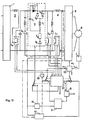
- the control torque is inverted from the shaping element 8 and the sequence begins with the blocking of the chopper 3 and the simultaneous commissioning by the sequencing element 12 piloting by varying the polarity at the terminals of the inverter 5 to maintain the current through the freewheeling diode DR 1 within limits imposed by the current regulating element 10 used in transient state.
- the operation continues with the closing of the contactor K s for low value currents since the average transition current is comparable to the magnetizing current of the machine. From this moment the current is distributed along two parallel branches, one comprising the contactor K s in the closed position, the other the freewheeling diode DR 1 .
- the contactor K4 is therefore opened without arcing (see Figure 8).
- the next phase (see FIG. 9) consists in re-lighting the main thyristor Th 1 without putting the extinguishing circuit into service and then in opening the contactor K s .
- the piloting is stopped by changing the polarity at the terminals of the inverter 5 by bringing the contactors Cm 1 , Cm 2 and Cm 3 to the position corresponding to normal speed and braking by recovery is continued.
- the correct polarity shown in FIG. 9, for operating the asynchronous machine 6 as a generator.
- the operator controls the operation by the shaping element 8.
- the sequencing element 12 controls the closing of the contactor K 4 then authorizes a new start-up.
- This same control device by varying the polarity across the terminals of the inverter can also be applied in the event of a dropout in thyristor rectifiers operating in recovery mode. There are many reasons for dropping out; they can be due to a significant overcurrent, to a bad lighting of a thyristor or to a fall of the alternating primary voltage.
- FIG. 10 represents a thyristor rectifier 14 made up of six thyristors and connected on the one hand to a three-phase primary network and on the other hand, via a smoothing inductor 4, to an inverter 5 supplying an asynchronous machine 6 at variable frequency. If, for example, a drop in voltage occurs at the three-phase primary source, during recovery operation, the control of the rectifier thyristors 14 becomes faulty since the switching time is inversely proportional to the voltage of the source.
- the device simultaneously controls the opening of the circuit breaker 15 and the piloting by variation of the polarity at the terminals of the inverter 5.
- the sequencing element 12 controls the opening of the circuit breaker 15. Simultaneously the sequencing element 12 connects the switches Cm ,, Cm 2 and Cm 3 in the transient phase position to allow piloting by varying the polarities at the terminals of the inverter 5 and thus maintain the value of the current flowing in the smoothing reactor 4 within the limits imposed by the current regulating element 10 used in transient state.
- this control device for traction equipment makes it possible, when a stall occurs under regenerative braking, to maintain a sufficient flow while awaiting the next acceleration or deceleration.
- the device for controlling by varying the polarity at the terminals of the inverter can still be applied when a running convoy is no longer supplied with electrical energy following a breakdown or an accident of the main source or even when, following an accident, the electronic power circuit must be quickly isolated from its main source. It can also allow the driver to cut off the power and let the convoy continue its momentum while providing the possibility, at any time, to brake or accelerate according to traffic requirements.
- this control device makes it possible to use the energy available in the rotating masses to maintain in the asynchronous machine, momentarily without power, a level flux determined to ensure by an appropriate sequence an electric braking.
- control devices acting on the sequencing element 12 are different depending on the urgency of the intervention.
- the cockpit is provided with an additional control which, by acting on the sequencing element 12, keeps the steering device at the last stage of the transient process.
- the electronic power diagram comprising a thyristor rectifier 14 is modified by the parallel mounting on the rectifier 14 of a freewheeling thyristor.
- the control of the sequencing element 12 is made on the basis of a measurement of the voltage on the capacitor of the input filter or of the current in the smoothing inductor 4.
- the electronic power circuit must be modified somewhat.
- FIGS. 11 and 12 show the diagrams respectively used for rheostatic braking and regenerative braking in the case of a power circuit comprising a diode rectifier 1.
- FIG. 13 represents a power circuit comprising a thyristor rectifier 14.
- FIG. 11 represents a diagram corresponding to the extended transition state for an electronic power circuit adapted to rheostatic braking.
- the sequencing element 12 switches the switches Cm 1 , Cm 2 and Cm 3 to the speed position transient and controls the ignition of the extinction thyristor Th 2 to block the chopper 3 by extinguishing the thyristor Th ,.
- the sequencing element 12 then controls the opening of the ultra-fast circuit breaker K a to isolate the electronic power circuit from its supply of electrical energy.
- the sequencer element 12 then re-ignites the main thyristor Th, of the chopper 3, extinguishing circuit inhibited and then controls the opening of the contactors K 2 and K 3 .
- the modular value of the rotor pulsation ⁇ z is, in the simplest case, supplied, by the element with constant reference 16, to the synthesizer element 13 which receives, on the other hand, the value P ⁇ r , read by the speed sensor element 7.
- the current regulating element 10 provides the sign affecting the rotor pulsation ⁇ 2 to the synthesizing element 13 to allow the latter to impose, at the terminals of the 'inverter 5, the correct polarities according to the value of the stator pulsation ⁇ 1 and thus operate the asynchronous machine 6 alternately as a motor or generator.
- This transition state can continue as long as the convoy is able to convert the energy of the rotating masses into electrical energy.
- the operator takes care of the possibility of braking or re-accelerating according to the needs of the moment.
- the operator imposes a positive torque on the shaping element 8 which in turn transmits the information to the sequencing element 12.
- the latter first controls the switching of the switch Cm 3 and imposes on the synthesizer element 13 a positive sign affecting the modular value of the roto pulse risk ⁇ 2 .
- the synthesizer element 13 imposes a value of the stator pulsation ⁇ 1 on the inverter 5 corresponding to the appropriate polarity (positive polarity on the input of the inverter in series with the smoothing inductor 4) to operate the asynchronous machine 6 as a motor. Maintaining this polarity at the terminals of the inverter 5 results in a progressive reduction of the current flowing in the smoothing reactor 4 until it is canceled.
- the sequencer element 12 When the sequencer element 12 is informed of the cancellation of the current in the smoothing reactor 4, it controls the switching of the contactors Cm 1 and Cm 2 in the normal operating position, then the closing of the contactors K s , K 2 and K 3 . In this way, we find the configuration indicated above in Figure 1, corresponding to the traction. Another way of proceeding would be, in order to avoid the cancellation of the current in the smoothing inductor 4, to impose via the element 12, taking into account the information which it receives, the closing of the power contactors K 2 and K 3 , then the blocking of Th 1 and the closing of K 6 , finally the switching of the switches Cm ,, Cm 2 and Cm 3 in the normal operating position corresponding to the traction. This avoids having to carry out a new starting sequence since at no time was the current interrupted in the inverter 5 and in the machine 6.
- the sequencing element 12 informed by the measurement of the current flowing in the smoothing reactor 4 and / or the measurement of the voltage across the terminals of the capacitor of the input filter 2, immediately orders the opening of the ultra-fast circuit breaker K 6 and the switching of the switches Cm 1 , Cm 2 and Cm a in a transient state.
- the sequencer element 12 checks the ignition of the main thyristor Th 1 of the chopper 3, extinguishing circuit inhibited, then opens the contactors K 2 and K 3 .
- the control device imposes the appropriate polarities at the terminals of the inverter 5 to maintain the flow in the asynchronous machine 6 at a determined value.
- This prolonged transition state makes it possible in particular to control the braking of the convoy with sufficient efficiency if necessary.
- FIG. 12 represents a diagram corresponding to the extended transition state for an electric power circuit adapted to regenerative braking.
- the driver of the moving convoy has a control lever acting directly on the sequencing element 12.
- the element sequencer 12 switches the switches Cm 1 , Cm 2 and Cm 3 and blocks the chopper 3 by switching off the main thyristor Th 1 . Then open the contactor K 4 .
- the sequencing element 12 After having ordered the re-ignition of the main thyristor Th 1 , of the chopper 3, extinguishing circuit inhibited, the sequencing element 12 finally controls the opening of the contactor K s .
- the modular value of the rotor pulsation ⁇ 2 is, in the simplest case, supplied by the element with constant reference 16 to the synthesizer element 13 which receives, on the other hand, the value P ⁇ r noted by the speed sensor element 7.
- the current regulator element 10 supplies, depending on the value of the current flowing in the smoothing reactor 4, the sign, affecting the rotor pulsation ⁇ 2 , to the synthesizer element 13.
- the synthesizer element 13 imposes, by the value of the stator pulsation ⁇ 1 , the polarities at the terminals of the inverter 5 to operate the asynchronous machine 6 alternately as a motor or as a generator. and thus maintain a determined flow in the machine.
- This state of transition can be prolonged as long as the convoy is moving and gives the operator the possibility of braking or re-accelerating at will.
- Braking is obtained by imposing a negative torque on the shaping element 8 which transmits the information to the sequencing element 12.
- the latter switches the switches Cm 1 , Cm 2 and Cm 3 to the normal operating position. From this moment, we find the configuration indicated previously in Figure 9 and corresponding to regenerative braking.
- the operator imposes a positive torque on the shaping element 8 which transmits the information to the sequencing element 12.
- the latter first controls the switching of the switch Cm 3 and imposes on the synthesizing element 13 a positive sign affecting the modular value of the rotor pulsation ⁇ 2 .
- the synthesizer element 13 imposes a value of the stator pulsation ⁇ 1 on the inverter 5 corresponding to the appropriate polarity (positive polarity on the input of the inverter in series with the smoothing inductor 4) to operate the asynchronous machine 6 as a motor. Maintaining this polarity at the terminals of the inverter 5 results in a progressive reduction of the current flowing in the smoothing reactor 4 until it is canceled.
- the sequencer element 12 When the sequencer element 12 is informed of the cancellation of the current in the smoothing reactor 4, it controls the switching of the contactors Cm 1 and Cm 2 in the normal operating position, then the closing of the contactors K 4 . We then find the configuration indicated above in Figure 6 and corresponding to the traction.
- the sequencer element 12 informed of the accident by measuring the current flowing in the smoothing reactor 4 and / or measuring the current flowing in the smoothing reactor 4 and / or measuring the voltage across the capacitor of the filter 2, immediately controls the opening of the ultra-fast circuit breaker K 6 and the switching of the switches Cm ,, Cm 2 , Cm 3 in the transient position.
- the sequencer element 12 checks the ignition of the main thyristor Th, of the chopper 3 and then opens the contactor K 4 .
- control device imposes the appropriate polarities at the terminals of the inverter 5 to maintain the flow in the asynchronous machine 6, at a determined value throughout the duration of this prolonged transition state. In this way, it is possible, at any time, to brake the convoy with sufficient efficiency.
- FIG. 13 represents a diagram corresponding to the extended transition state for a power electronic circuit comprising a thyristor rectifier 14. The processes leading to this extended transition state differ according to the voluntary operation or the emergency intervention .
- the process starts by actuating the control lever of the sequencing element 12 which reflects the order by inhibiting the control of the thyristors T ,, T 2 , T 3 , T 4 , T 5 , T 6 of the rectifier 14.
- the sequencing element 12 then controls the switching of the switches Cm 1 , Cm 2 , Cm 3 and the ignition of the freewheel thyristor Th r1 .
- the sequencing element 12 reacts according to the measurement of the current flowing in the smoothing reactor 4 to first control the opening of the circuit breaker 15, then the switching of the switches Cm ,, Cm 2 , Cm 3 and the ignition of two thyristors of the same branch of the rectifier 14, for example the thyristors T 1 and T 4 as shown in FIG. 13.
- the sequencing element 13 receives respectively: the modular value of the rotor pulsation ⁇ 2 supplied, in the simplest case, by the reference element constant 16, the sign affecting ⁇ 2 supplied by the regulating element 10 according to the value of the current flowing in the smoothing reactor 4, the value P ⁇ r noted by the speed sensor element 7, to impose on the inverter 5 the value of the stator pulsation ⁇ 1 , and thus operate the asynchronous machine 6 alternately as a motor or generator so as to maintain a determined flow in the machine.
- the extended transition state provides immediate access to braking or traction by simple command from the cockpit.
- the synthesizer element 13 imposes a value of the stator pulsation ⁇ 1 , on the inverter 5 corresponding to the appropriate polarity (positive polarity on the input of the inverter in series with the smoothing inductor 4) to make operate the asynchronous machine 6 as a motor. Maintaining this polarity at the terminals of the inverter 5 results in a progressive reduction of the current flowing in the smoothing reactor 4 until it is canceled.
- the sequencer element 12 is informed of the cancellation of the current in the smoothing inductor 4, it commands the switching of the contactors Cm 1 and Cm 2 to give the diagram the configuration corresponding to the normal regime allowing a traction sequence to be established .
- braking is obtained by requesting a negative torque from the shaping element 8.
- the shaping element 8 associated with the sequencing element 12 toggle the switch Cm 3 and impose a positive sign on ⁇ 2 on the synthesizing element 13. Consequently, the stator pulse ⁇ 1 , emitted by the synthesizer element 13, imposes the polarities at the terminals of the inverter 5 corresponding to the motor operation of the asynchronous machine 6. In this way, the current flowing in the electronic power circuit is canceled and the thyristors T 1 and T 4 of the rectifier 14 go out. From this moment the sequencer element 12 commands the closing of the circuit breaker 15 then toggles the switches Cm, and Cm 2 to give the diagram its configuration of normal regime and allow to operate a traction sequence.
- the rest of the process takes place as before to bring the asynchronous machine 6 to regain sufficient flow by a short pulling sequence.
- the shaping element 8 associated with the sequencing element 12 then impose a negative sign on ⁇ 2 on the synthesizing element 13.
- the synthesizer element 13 by the value of the stator pulse ⁇ 1 , imposes on the terminals of the inverter 5 the polarities corresponding to the generator operation of the synchronous machine.
Landscapes
- Engineering & Computer Science (AREA)
- Power Engineering (AREA)
- Transportation (AREA)
- Mechanical Engineering (AREA)
- Stopping Of Electric Motors (AREA)
- Control Of Ac Motors In General (AREA)
- Electric Propulsion And Braking For Vehicles (AREA)
Description
- L'invention concerne un dispositif de pilotage par variation de la polarité aux bornes d'un onduleur alimentant une machine asynchrone. Dès qu'une inversion de couple est demandée, ce dispositif impose une configuration propre à la phase transitoire pour isoler le hacheur de la source de tension continue et inverser les polarités aux bornes de l'onduleur par variations alternatives du signe affectant la valeur modulaire de la pulsation rotorique par un élément régulateur de courant.
- Lorsque, dans une machine à courant continu, on réalise le passage d'une configuration de traction à une configuration de freinage, en utilisant des contacteurs basculés uniquement en l'absence de courant, on interrompt d'abord l'alimentation de la machine à courant continu en bloquant les hacheurs pendant la commutation des contacteurs. On réexcite, ensuite, la machine à l'aide d'un dispositif de prémagnétisation jusqu'à ce qu'elle soit à nouveau capable d'entretenir son propre flux.
- La transposition de cette technique en machine asynchrone ne peut pratiquement pas s'envisager en traction électrique tant un dispositif auxiliaire remplissant la même fonction serait encombrant et compliqué. Une autre possibilité, valable uniquement pour les grosses machines asynchrones serait d'annuler le courant et de basculer les contacteurs pour mettre le circuit en configuration de freinage en un temps très court. On dispose en effet d'une constante de temps de l'ordre de la seconde pendant laquelle subsiste un flux suffisant pour amorcer le fonctionnement en génératrice. Cette solution ne présente guère les garanties de sécurité requises et n'est pas applicable à des machines asynchrones de moindre puissance dont la constante de temps rotorique est de l'ordre du dixième de seconde.
- Un autre moyen utilisé consiste à changer la configuration du circuit sans attendre l'annulation du courant continu. Cette opération est rendue délicate par l'utilisation de contacteurs rapides souvent générateurs de surtensions aux bornes des différents composants électroniques. De plus, ces composants demandent des inspections et des entretiens fréquents pour conserver un niveau de fiabilité acceptable.
- La présente invention se réfère à un dispositif de pilotage selon le préambule de la revendication 1 tel qu'il est connu du document FR-A-2 333 312. Ce document décrit un circuit de commande prévu, en particulier, pour le freinage rhéostatique d'un moteur à courant alternatif, alimenté à partir d'un onduleur de courant, en contrôlant la puissance dissipée dans la résistance de freinage afin d'assurer le développement d'un couple constant lors de l'opération de freinage. Dans ce circuit, l'ouverture et la fermeture des commutateurs sont simplement coordonnés à un inverseur, qui permet de passer de la position de traction à la position de freinage. De ce fait les commutateurs risquent de se dégrader plus rapidement et doivent faire l'objet d'inspections plus fréquentes.
- L'invention telle qu'elle est proposée dans la revendication 1 supprime les inconvénients précités.
- Elle fait intervenir un artifice de commande qui comporte une suite de séquences permettant à un circuit approprié de déconnecter la source de tension continue et de prendre la configuration adaptée au freinage pendant que, par pilotage électronique, les polarités aux bornes de l'onduleur sont inversées pour maintenir le courantcirculant dans la self de lissage, montée entre le hacheur et l'onduleur, à un niveau moyen prédéterminé.
- L'invention sera explicitée dans ses détails à l'aide des figures suivantes:
- Les figures 1, 2, 3, 4 et 6 à 13 montrent l'ensemble de l'installation respectivement en phase de traction, de transition et de freinage rhéostatique.
- La figure 5 illustre l'évolution du courant moyen dans la self de lissage Ls en regard de l'évolution de la valeur de pilotage de la pulsation statorique ω1.
- La figure 1 représente un redresseur 1 à diodes qui, par l'intermédiaire d'un filtre 2, est relié à un hacheur 3 lui-même raccordé à un onduleur 5 par une self de lissage 4.
- L'onduleur 5 est relié à une machine asynchrone 6 dont la vitesse de rotation est relevée par un capteur de vitesse 7.
- L'opérateur modifie à volonté le couple de traction demandé au moteur asynchrone 6 en agissant sur le poste 8 qui répercute l'information vers le poste 9 pour imposer le point de fonctionnement de la machine.
- Dans la figure 1, représentant l'installation en configuration de traction, le courant qui traverse l'onduleur 5 et le moteur asynchrone 6 parcourt le circuit formé soit par le redresseur 1 lorsque le hacheur 3 conduit, soit par la diode de roue libre D,, lorsque le hacheur 3 est bloqué. Le rapport cyclique réglable permet au hacheur 3 de modifier le courant dans la self de lissage 4 et de faire varier ainsi le couple de traction du moteur asynchrone 6. Le circuit de commande comprenant tous les postes numérotés de 7 à 13, 16 répond, en phase traction, à l'équation ω↑ = PωR+ω2 dans laquelle ω↑ est la pulsation statorique générée en l'élément synthétiseur 13, ω2 la pulsation rotirique, réglable en valeur modulaire par l'élément calculateur du point de fonctionnement 9, et Pωr la mesure de la vitesse de rotation de l'arbre du moteur asynchrone 6 faite par le capteur de vitesse 7. Le signe + affectant ro2 dépend du signe du couple de traction demandé à l'élément conformateur 8 depuis le poste de commande.
- La figure 2 représente la première séquence de la phase de transition. Lorsque l'opérateur désire faire intervenir le frein rhéostatique en actionnant le levier de commande, il agit sur l'élément conformateur 8 qui, dès l'inversion de signe du couple électromagnétique souhaité, met l'installation en phase transitoire.
- Dès ce moment, des circuits de commande vont intervenir simultanément pour, d'une part, déconnecter le hacheur 3 de la source à tension continue, le redresseur 1, et brancher le hacheur 3 en parallèle sur la résistance rhéostatique de freinage Rfr via une diode de freinage Dfr et, d'autre part, inverser les polarités aux bornes de l'onduleur pour faire circuler un courant dans la self de lissage 4 capable d'entretenir un flux suffisant dans la machine asynchrone 6.
- Dans un but de clarté, nous analyserons ces différentes actions les une après les autres, étant bien entendu que dans la réalité leur déroulement est simultané.
- Dès que l'opérateur actionne le levier de commande pour réclamer le freinage, sa manoeuvre, correspondant à une inversion de la consigne du couple, est enregistrée en l'élément conformateur 8, et l'élément séquenceur 12 impose au dispositif de commande la configuration propre à la phase transitoire par basculement des trois commutateurs Cm,, Cm2, Cm3. L'allumage du thyristor auxiliaire Th2 provoque la fermeture du circuit d'extinction C1L1 et l'établissement d'un courant qui entraîne l'extinction du thyristor principal Th,. Dès que le thyristor principal Th1 ne conduit plus, on ouvre le contacteur K1 pour isoler le hacheur 3 de la source de tension continue, le redresseur 1.
- A cause de la caractéristique selfique du circuit, renforcée notamment par la présence de la self de lissage 4, le courant ne s'annule pas instantanément et continue à circuler en passant par la diode de roue libre Drl.
- La figure 3 correspond à la deuxième séquence de la phase transitoire. Elle représente l'installation à partir du moment où, en allumant à nouveau le thyristor principal Th1 tout en inhibant la commande du circuit d'extinction, on offre au courant la possibilité de passer à travers la diode de freinage Dfr. On peut dès lors ouvrir simultanément les contacteurs K2 et K3
- La figure 4 représente l'installation en phase de freinage. Cette phase débute dès que les contacteurs K2 et K3 sont ouverts. A partir de ce moment, le circuit d'extinction du hacheur 3 piloté par le régulateur de courant 11 dans la self de lissage 4 est remis en service. Les commutateurs Cm,, Cm2, Cm3 sont basculés pour retrouver leur position normale et le hacheur travaille à nouveau normalement c'est-à-dire que par blocages et déblocages successifs du thyristor principal Thi, on alterne le passage du courant soit dans la diode de freinage Dfr, soit dans la résistance rhéostatique de freinage Rf
r pour disposer ainsi d'un freinage rhéostatique contrôlé. - Pendant les deux séquences de la phase transitoire exposées respectivement dans les figure 2 et 3, le dispositif de commande a été mis en configuration de transition par l'élément 12 pour répondre à l'équation ω1 = Pωr±ω2 dans laquelle ω2, est, dans le cas le plus simple, maintenu à une valeur fixe par l'élément à consigne constante 16. Durant cette phase transitoire le signe de ω2 est rendu alternativement positif et négatif selon la valeur du courant mesurée dans la self de lissage 4 et comparée par exemple dans l'élément régulateur de courant 10 utilisé en période transitoire à deux seuils prédéterminés.
- Tout au long de cette phase transitoire, aussi longtemps que tourne la machine asynchrone 6, l'onduleur 5, déconnecté de la source de tension continue, le redresseur 1, est piloté par l'élément synthétiseur 13 qui applique une consigne de pulsation statorique ω1, alternativement supérieure ou inférieure à la mesure de vitesse Pro, relevée par le capteur de vitesse 7.
- Il est à remarquer que durant la phase transitoire, la pulsation rotorique ω2 peut être réglée de deux façons différentes. Dans une première manière d'opérer, la pulsation rotorique ω2 est une valeur fixe, fournie par l'élément à consigne constante 16 pendant la phase transitoire. La seconde manière de régler la pulsation rotorique ω2 consiste à imposer une valeur déterminée selon les variations enregistrées par l'élément régulateur de courant 10 utilisé en régime transitoire.
- Notons que l'élément régulateur de courant 10 peut être constitué par la mise en cascade de la régulation de courant précitée et d'une régulation de tension à l'entrée de l'onduleur dont la consigne serait la sortie du régulateur de courant 10, utilisé en régime transitoire. Cette manière de procéder permet un réglage plus efficace de la fréquence rotorique lors du fonctionnement en régime de transition.
- Des traits mixtes rappellent, dans les différentes figures, cette double possibilité du réglage de la pulsation rotorique ω2.
- La figure 5 montre que, dans le cas où l'on réalise l'addition de la valeur généralement constante ω2 à la valeur mesurée Pωr, la machine à induction fonctionnant en moteur impose la décroissance du courant unidirectionnel dans la self de lissage 4.
- Cette même figure 5 montre encore que dès que l'amplitude de ce courant devient inférieure à un seuil fixé on effectue la soustraction du terme généralement constant ω2 de la valeur mesurée Pωr de manière que la machine, fonctionnant en génératrice, réalise la conversion de l'énergie cinétique des masses en rotation en énergie électrique et impose, via l'onduleur 5 dont la tension aux bornes s'est inversée, l'augmentation du courant qui circule dans la self de lissage 4. Quand l'amplitude du courant circulant dans la self de lissage 4 atteint le seuil supérieur on effectue à nouveau l'addition de ω2 et de Pωr pour faire fonctionner la machine en moteur et réduire à nouveau le courant circulant dans la self 4. Cette opération peut être répétée aussi longtemps que la tension aux bornes de l'onduleur 5 est suffisante, c'est-à-dire aussi longtemps que la ma- chine asynchrone 6 tourne à une vitesse suffisante. Elle se traduit en fin de compte par une suite de changements de polarité aux bornes de l'onduleur 5.
- Le volant d'inertie des masses en rotation procure un temps largement suffisant pour mettre le circuit en configuration de freinage par l'ouverture des trois contacteurs Kl, K2 et K3 isolant le hacheur 3 du redresseur 1 et la mise en parallèle de la résistance de freinage R,, sur le hacheur 3. Lors du passage du freinage à la traction, l'opération est commandée au départ de l'élément conformateur 8 par une nouvelle inversion du couple demandé. L'élément calculateur du point de fonctionnement 9 impose alors une consigne de courant nulle.
- Après avoir vérifié l'annulation du courant dans la machine asynchrone, l'élément séquenceur 12 commande la fermeture simultanée des contacteurs K,, K2 et K3 et, ensuite, autorise un nouveau processus de démarrage même si la machine est en rotation.
- Une autre application du dispositif de pilotage par variation de la polarité aux bornes de l'onduleur revendiqué dans cette invention est relative au freinage par récupération utilisé dans les applications de traction électrique. Les différentes phases de la manoeuvre sont reprises dans les figures 6, 7, 8 et 9.
- La figure 6 représente en phase de traction l'ensemble d'une installation adaptée au freinage par récupération.
- Ce schéma se distingue par le montage, en parallèle sur la diode de freinage Dfr via le hacheur 3 d'un contacteur Ks dimensionné pour couper des courants de faible valeur. Quant au contacteur K4, il permet, par son ouverture, l'inversion des liaisons des bornes d'entrée de l'onduleur aux potentiels positif et négatif du condensateur du filtre d'entrée. Dans ce mode de freinage, la machine asynchrone fonctionne en génératrice et l'énergie qu'elle engendre est renvoyée dans le réseau.
- En configuration de traction le contacteur K4 est fermé, le contacteur K5 est ouvert. De la sorte, le courant traversant l'onduleur 5 et la machine asynchrone 6 parcourt soit le circuit formé par le redresseur 1 lorsque le hacheur 3 conduit, soit passe par la diode de roue libre DR1 lorsque le hacheur est bloqué.
- Dès la demande de freinage (voir la figure 7), il y a inversion du couple de commande à partir de l'élément conformateur 8 et la séquence débute par le blocage du hacheur 3 et la mise en service simultanée par l'élément séquenceur 12 du pilotage par variation de la polarité aux bornes de l'onduleur 5 pour maintenir le courant à travers la diode de roue libre DR1 dans des limites imposées par l'élément régulateur de courant 10 utilisé en régime transitoire. L'opération se poursuit par la fermeture du contacteur Ks pour des courants de faible valeur puisque le courant moyen de transition est comparable au courant magnétisant de la machine. A partir de ce moment le courant se répartit suivant deux branches parallèles, comprenant l'une le contacteur Ks en position fermée, l'autre la diode de roue libre DR1. L'ouverture du contacteur K4 se fait donc sans formation d'arc (voir la figure 8). La phase suivante (voir figure 9) consiste à réallumer le thyristor principal Th1 sans mettre en service le circuit d'extinction puis à ouvrir le contacteur Ks.
- Lorsque le contacteur Ks est ouvert, on arrête le pilotage par changement de la polarité aux bornes de l'onduleur 5 en ramenant les contacteurs Cm1, Cm2 et Cm3 en position correspondant au régime normal et on poursuit le freinage par récupération en maintenant aux bornes de l'onduleur 5 la polarité adéquate, représentée en figure 9, pour faire travailler la machine asynchrone 6 en génératrice.
- Pour repasser du freinage à la traction, l'opérateur commande la manoeuvre par l'élément conformateur 8. Après avoir vérifié l'annulation du courant dans la machine asynchrone, l'élément séquenceur 12 commande la fermeture du contacteur K4 puis autorise un nouveau démarrage.
- Ce même dispositif de pilotage par variation de la polarité aux bornes de l'onduleur peut également s'appliquer en cas de décrochage dans les redresseurs à thyristors fonctionnant en récupération. Les causes de décrochage sont multiples; elles peuvent être dues à une surintensité importante, à un mauvais allumage d'un thyristor ou encore à une chute de la tension primaire alternative.
- Sans précaution spéciale, le décrochage dégénère rapidement en un claquage de fusibles du pont. Cet incident est particulièrement lourd de conséquences pour le matériel ferroviaire qui, dans ce cas, doit être remorqué en atelier de réparation.
- La figure 10 représente un redresseur à thyristors 14 constitué de six thyristors et raccordé d'une part à un réseau primaire triphasé et d'autre part, via une self de lissage 4, à un onduleur 5 alimentant à fréquence variable une machine asynchrone 6. Si par exemple, une baisse de tension apparaît à la source primaire triphasée, lors d'un fonctionnement en récupération, le pilotage des thyristors de redresseur 14 devient défectueux puisque le temps de commutation est inversement proportionnel à la tension de la source.
- Dans le cas de la figure 10, supposons que cette baisse de tension survienne alors que le thyristor T1 est allumé. Son temps de commutation étant plus long, T, ne sera pas éteint pendant la conduction de T3 et le courant parcourant T1 aura alors tendance à s'accroître en réduisant davantage ses possibilités d'extinction. Le thyristor T, sera encore allumé lorsqu'à son tour s'allumera l'autre thyristor T4 de la même branche. L'allumage simultané de T1 et T4 donne lieu à un court-circuit qui ne pourra s'interrompre que par l'intervention des fusibles de protection.
- Les inconvénients précités sont évités par le dispositif de pilotage par changement des polarités aux bornes de l'onduleur qui, par son intervention, empêche non seulement la destruction des thyristors mais également celle des fusibles de protection. Son utilisation supprime donc toute rupture d'exploitation du redresseur à thyristors.
- Dès qu'un décrochage de la source primaire triphasée est détecté, le dispositif commande simultanément l'ouverture du disjoncteur 15 et le pilotage par variation de la polarité aux bornes de l'onduleur 5.
- Lorsque le court-circuit affecte la branche contenant les thyristors T1 et T4 lors d'un fonctionnement en récupération, l'élément séquenceur 12, selon le courant circulant dans la self de lissage 4, commande l'ouverture du disjoncteur 15. Simultanément l'élément séquenceur 12 branche les commutateurs Cm,, Cm2 et Cm3 en position de phase transitoire pour permettre le pilotage par variation des polarités aux bornes de l'onduleur 5 et ainsi maintenir la valeur du courant circulant dans la self de lissage 4 dans des limites imposées par l'élément régulateur de courant 10 utilisé en régime transitoire.
- D'autre part, l'utilisation de ce dispositif de pilotage pour du matériel de traction permet, lorsque se présente un décrochage en freinage par récupération, de maintenir un flux suffisant dans l'attente d'une prochaine accélération ou décélera- tion.
- Le dispositif de pilotage par variation de la polarité aux bornes de l'onduleur peut encore s'appliquer lorsqu'un convoi en marche n'est plus alimenté en énergie électrique suite à une panne ou à un accident de la source principale ou encore lorsque, à la suite d'un accident, il faut isoler rapidement le circuit électronique de puissance de sa source principale. Il peut également permettre au conducteur de couper l'alimentation et de laisser le convoi poursuivre sur sa lancée tout en se ménageant la possibilité, à tout instant, de freiner ou de réaccélérer selon les nécessités du trafic.
- En effet, ce dispositif de pilotage permet d'utiliser l'énergie disponible dans les masses en rotation pour maintenir dans la machine asynchrone, momentanément sans alimentation, un flux de niveau déterminé pour assurer par une séquence appropriée un freinage électrique.
- Pour utiliser de la sorte les masses en rotation, les dispositifs de commande agissant sur l'élément séquenceur 12 sont différents selon l'urgence de l'intervention.
- Pour la commande volontaire le poste de pilotage est muni d'une commande supplémentaire qui, en agissant sur l'élément séquenceur 12, maintient le dispositif de pilotage au dernier stade du processus transitoire. Le schéma électronique de puissance comprenant un redresseur à thyristors 14 est modifié par le montage en parallèle sur le redresseur 14 d'un thyristor de roue libre.
- Au contraire, si l'intervention doit être rapide, suite par exemple à un court-circuit sur la caténaire ou à la disparition soudaine de celle-ci, la commande de l'élément séquenceur 12 est faite au départ d'une mesure de la tension sur le condensateur du filtre d'entrée ou du courant dans la self de lissage 4. De plus, le circuit électronique de puissance doit être quelque peu modifié.
- Dans le cas du freinage rhéostatique, le contacteur K1 est remplacé par un disjoncteur ultra-rapide KG (voir la figure 11). Dans le cas du freinage par récupération un disjoncteur ultra rapide K6 doit être monté à l'amont du condensateur du filtre 2 pour isoler le circuit de la source de tension (voir figure 12).
- Les figures 11 et 12 montrent les schémas respectivement utilisés pour le freinage rhéostatique et le freinage par récupération dans le cas d'un circuit de puissance comprenant un redresseur à diodes 1. La figure 13 représente un circuit de puissance comprenant un redresseur à thyristors 14.
- La figure 11 représente un schéma correspondant à l'état de transition prolongé pour un circuit électronique de puissance adapté au freinage rhéostatique.
- Lorsque le conducteur choisit le fonctionnement sans alimentation, il manoeuvre un levier de commande qui agit directement sur l'élément séquenceur 12. Suite à cette manoeuvre, l'élément séquenceur 12 bascule les commutateurs Cm1, Cm2 et Cm3 en position de régime transitoire et commande l'allumage du thyristor d'extinction Th2 pour bloquer le hacheur 3 en éteignant le thyristor Th,.
- L'élément séquenceur 12 commande ensuite l'ouverture du disjoncteur ultra-rapide Ka pour isoler le circuit électronique de puissance de son alimentation en énergie électrique.
- L'élément séquenceur 12 réallume ensuite le thyristor principal Th, du hacheur 3, circuit d'extinction inhibé puis commande l'ouverture des contacteurs K2 et K3.
- Pendant ce temps, la valeur modulaire de la pulsation rotorique ωz est, dans le cas le plus simple, fournie, par l'élément à consigne constante 16, à l'élément synthétiseur 13 qui reçoit, d'autre part, la valeur Pωr, relevée par l'élément capteur de vitesse 7.
- Simultanément selon la valeur du courant circulant dans la self de lissage 4, l'élément régulateur de courant 10 fournit le signe affectant la pulsation rotorique ω2 à l'élément synthétiseur 13 pour permettre à celui-ci d'imposer, aux bornes de l'onduleur 5, les polarités adéquates selon la valeur de la pulsation statorique ω1 et d'ainsi faire fonctionner la machine asynchrone 6 alternativement en moteur ou en générateur.
- Cet état de transition peut se prolonger aussi longtemps que le convoi est capable de convertir l'énergie des masses en rotation en énergie électrique. Pendant cette période transitoire prolongée, reprise en figure 11, l'opérateur se ménage la possibilité de freiner ou de réaccélérer selon les besoins du moment.
- Pour assurer le freinage, il suffit d'imposer un couple négatif à l'élément conformateur 8 qui transmet l'information à l'élément séquenceur 12. Celui-ci commande le basculement des commutateurs Cm,, Cm2 et Cm3 dans leur position de fonctionnement normal. Dès ce moment, on retrouve la configuration, indiquée précédemment en figure 4, correspondant au freinage rhéostatique.
- Pour obtenir une accélération, l'opérateur impose un couple positif à l'élément conformateur 8 qui transmet à son tour l'information vers l'élément séquenceur 12. Ce dernier commande d'abord le basculement du commutateur Cm3 et impose à l'élément synthétiseur 13 un signe positif affectant la valeur modulaire de la pulsation rotorique ω2. De la sorte l'élément synthétiseur 13 impose une valeur de la pulsation statorique ω1 à l'onduleur 5 correspondant à la polarité adéquate (polarité positive sur l'entrée de l'onduleur en série avec la self de lissage 4) pour faire fonctionner la machine asynchrone 6 en moteur. Le maintien de cette polarité aux bornes de l'onduleur 5 entraîne une réduction progressive du courant circulant dans la self de lissage 4 jusqu'à son annulation. Lorsque l'élément séquenceur 12 est informé de l'annulation du courant dans la self de lissage 4, il commande le basculement des contacteurs Cm1 et Cm2 en position de régime normal, puis la fermeture des contacteurs Ks, K2 et K3. De la sorte, on retrouve la configuration indiquée précédemment en figure 1, correspondant à la traction. Une autre manière de procéder serait, afin d'éviter l'annulation du courant dans la self de lissage 4, d'imposer via l'élément 12, compte tenu des informations qu'il reçoit, la fermeture des contacteurs de puissance K2 et K3, ensuite le blocage de Th1 et la fermeture de K6, enfin le basculement des commutateurs Cm,, Cm2 et Cm3 en position de régime normal correspondant à la traction. On évite ainsi de devoir procéder à une nouvelle séquence de démarrage puisqu'à aucun moment le courant n'a été interrompu dans l'onduleur 5 et dans la machine 6.
- Par contre, si un accident oblige à déconnecter brusquement le circuit électronique de puissance de sa source d'alimentation, comme par exemple suite à un court-circuit sur la caténaire ou à la disparition soudaine de celle-ci, l'élément séquenceur 12, informé par la mesure du courant circulant dans la self de lissage 4 et/ou la mesure de la tension aux bornes du condensateur du filtre d'entrée 2, commande immédiatement l'ouverture du disjoncteur ultra-rapide K6 et le basculement des commutateurs Cm1, Cm2 et Cma en position de régime transitoire. L'élément séquenceur 12 vérifie ensuite l'allumage du thyristor principal Th1 du hacheur 3, circuit d'extinction inhibé, puis ouvre les contacteurs K2 et K3. Simultanément, et de la même manière que la manoeuvre volontaire ci- dessus décrite, le dispositif de pilotage impose les polarités adéquates aux bornes de l'onduleur 5 pour maintenir le flux dans la machine asynchrone 6 à une valeur déterminée. Cet état de transition prolongé permet notamment de commander en cas de besoin le freinage du convoi avec une efficacité suffisante.
- La figure 12 représente un schéma correspondant à l'état de transition prolongé pour un circuit électrique de puissance adapté au freinage par récupération.
- Pour exécuter la manoeuvre coupant volontairement l'alimentation du circuit électronique de puissance, le conducteur du convoi en marche dispose d'un levier de commande agissant directement sur l'élément séquenceur 12. Lorsque l'opérateur manoeuvre ce levier de commande, l'élément séquenceur 12 bascule les commutateurs Cm1, Cm2 et Cm3 et bloque le hacheur 3 en éteignant le thyristor principal Th1. Ensuite l'ouverture du contacteur K4. Après avoir commandé le réallumage du thyristor principal Th1, du hacheur 3, circuit d'extinction inhibé, l'élément séquenceur 12 commande finalement l'ouverture du contacteur Ks.
- Pendant ce temps, la valeur modulaire de la pulsation rotorique ω2 est, dans le cas le plus simple, fournie par l'élément à consigne constante 16 à l'élément synthétiseur 13 qui reçoit, d'autre part, la valeur Pωr relevée par l'élément capteur de vitesse 7. Simultanément, l'élément régulateur de courant 10 fournit, selon la valeur du courant circulant dans la self de lissage 4, le signe, affectant la pulsation rotorique ω2, à l'élément synthétiseur 13. De la sorte, après avoir reçu ces diverses informations, l'élément synthétiseur 13 impose, par la valeur de la pulsation statorique ω1, les polarités aux bornes de l'onduleur 5 pour faire fonctionner la machine asynchrone 6 alternativement en moteur ou en générateur et ainsi maintenir un flux déterminé dans la machine.
- Cet état de transition peut se prolonger aussi longtemps que le convoi roule et donne à l'opérateur la possibilité de freiner ou de réaccélérer à volonté.
- Le freinage est obtenu en imposant un couple négatif à l'élément conformateur 8 qui transmet l'information à l'élément séquenceur 12. Ce dernier bascule les commutateurs Cm1, Cm2 et Cm3 dans la position de fonctionnement normal. Dès ce moment, on retrouve la configuration indiquée précédemment à la figure 9 et correspondant au freinage par récupération.
- Pour obtenir une accélération, l'opérateur impose un couple positif à l'élément conformateur 8 qui transmet l'information à l'élément séquenceur 12. Ce dernier commande d'abord le basculement du commutateur Cm3 et impose à l'élément synthétiseur 13 un signe positif affectant la valeur modulaire de la pulsation rotorique ω2. De la sorte l'élément synthétiseur 13 impose une valeur de la pulsation statorique ω1 à l'onduleur 5 correspondant à la polarité adéquate (polarité positive sur l'entrée de l'onduleur en série avec la self de lissage 4) pour faire fonctionner la machine asynchrone 6 en moteur. Le maintien de cette polarité aux bornes de l'onduleur 5 entraîne une réduction progressive du courant circulant dans la self de lissage 4 jusqu'à son annulation. Lorsque l'élément séquenceur 12 est informé de l'annulation du courant dans la self de lissage 4, il commande le basculement des contacteurs Cm1 et Cm2 en position de régime normal, puis la fermeture des contacteurs K4. On retrouve alors la configuration indiquée précédemment à la figure 6 et correspondant à la traction.
- Une autre manière de procéder serait, afin d'éviter l'annulation du courant dans la self de lissage 4, d'imposer via l'élément 12 la fermeture du contacteur de puissance Ks, suivi du blocage de Th1' ensuite la fermeture de K4 et enfin l'ouverture de Ks suivie du basculement des commutateurs Cm1' Cm2 et Cm3 en position de régime de devoir procéder et une nouvelle séquence de démarrage puisque le courant n'est interrompu ni dans l'onduleur 5, ni dans la machine 6.
- Par contre, si un accident oblige à déconnecter brusquement le circuit électronique de puissance de son alimentation, par exemple suite à un court-circuit sur la caténaire, les opérations se déroulent comme suit. L'élément séquenceur 12, informé de l'accident par la mesure du courant circulant dans la self de lissage 4 et/ou la mesure du courant circulant dans la self de lissage 4 et/ou la mesure de la tension aux bornes du condensateur du filtre 2, commande immédiatement l'ouverture du disjoncteur ultra-rapide K6 et le basculement des commutateurs Cm,, Cm2, Cm3 en position de régime transitoire. L'élément séquenceur 12 vérifie ensuite l'allumage du thyristor principal Th, du hacheur 3 puis ouvre le contacteur K4. Simultanément, et de la manière précédemment décrite, le dispositif de pilotage impose les polarités adéquates aux bornes de l'onduleur 5 pour maintenir le flux dans la machine asynchrone 6, à une valeur déterminée pendant toute la durée de cet état de transition prolongé. De la sorte, on peut, à tout instant freiner le convoi avec une efficacité suffisante.
- Il est à remarquer que le même état de transition prolongé peut s'appliquer à un circuit électronique de puissance adapté au freinage mixte.
- La figure 13 représente un schéma correspondant à l'état de transition prolongé pour un circuit électronique de puissance comprenant un redresseur à thyristors 14. Les processus amenant à cet état de transition prolongé diffèrent selon la ma- nœuvre volontaire ou l'intervention d'urgence.
- Dans le cas d'une manoeuvre volontaire libérant le circuit électronique de puissance de la source primaire polyphasée, le processus démarre en actionnant le levier de commande de l'élément séquenceur 12 qui répercute l'ordre en inhibant la commande des thyristors T,, T2, T3, T4, T5, T6 du redresseur 14. L'élément séquenceur 12 commande ensuite le basculement des commutateurs Cm1, Cm2, Cm3 et l'allumage du thyristor de roue libre Thr1.
- Dans le cas d'une intervention d'urgence, suite par exemple à un court-circuit sur la caténaire, l'élément séquenceur 12 réagit selon la mesure du courant circulant dans la self de lissage 4 pour d'abord commander l'ouverture du disjoncteur 15, puis le basculement des commutateurs Cm,, Cm2, Cm3 et l'allumage de deux thyristors d'une même branche du redresseur 14, par exemple les thyristors T1 et T4 comme repris à la figure 13.
- Simultanément, et de la même manière pour les deux cas précités (manoeuvre ou urgence), l'élément séquenceur 13 reçoit respectivement: la valeur modulaire de la pulsation rotorique ω2 fournie, dans le cas le plus simple, par l'élément à consigne constante 16, le signe affectant ω2 fourni par l'élément régulateur 10 selon la valeur du courant circulant dans la self de lissage 4, la valeur Pωr relevée par l'élément capteur de vitesse 7, pour imposer à l'onduleur 5 la valeur de la pulsation statorique ω1, et ainsi faire fonctionner la machine asynchrone 6 alternativement en moteur ou en générateur de façon à maintenir un flux déterminé dans la machine.
- L'état de transition prolongé permet d'accéder immédiatement au freinage ou à la traction par simple commande effectuée au poste de pilotage.
- Dans le cas, où l'état de transition prolongé a été obtenu par une manoeuvre volontaire, une réaccélération est obtenue en demandant un couple positif à l'élément conformateur 8.
- L'élément conformateur 8 associé à l'élément séquenceur 12, informés de l'état du circuit de puissance, commandent le basculement du commutateur Cm3 et imposent à l'élément synthétiseur 13 un signe positif affectant la valeur modulaire de la pulsation rotorique ω2. De la sorte l'élément synthétiseur 13 impose une valeur de la pulsation statorique ω1, à l'onduleur 5 correspondant à la polarité adéquate (polarité positive sur l'entrée de l'onduleur en série avec la self de lissage 4) pour faire fonctionner la machine asynchrone 6 en moteur. Le maintien de cette polarité aux bornes de l'onduleur 5 entraîne une réduction progressive du courant circulant dans la self de lissage 4 jusqu'à son annulation. Lorsque l'élément séquenceur 12 est informé de l'annulation du courant dans la self de lissage 4, il commande le basculement des contacteurs Cm1 et Cm2 pour donner au schéma la configuration correspondant au régime normal permettant d'établir une séquence de traction.
- Au départ de l'état de transition prolongé, le freinage est obtenu en demandant un couple négatif à l'élement conformateur 8.
- Le processus ainsi engagé se déroule alors de la même façon que celui décrit pour la traction. En effet, il faut d'abord annuler le courant pour étein- dre le thyristor de roue libre Th,, puis retrouver un certain flux dans la machine par une courte séquence de traction. Dès l'instant où la valeur du flux dans la machine est suffisante l'élément conformateur 8 associé à l'élément séquenceur 12 imposent à l'élément synthétiseur 13 un signe négatif affectant la valeur modulaire de la pulsation rotorique ω2. Il en résulte une pulsation statorique ω1, émise par l'élément synthétiseur 13 pour imposer aux bornes de l'onduleur 5 les polarités correspondant au fonctionnement générateur de la machine asynchrone 6.
- Lorsque l'état de transition prolongé a été obtenu par une intervention automatique d'urgence basée sur la mesure du courant circulant dans la self de lissage 4, une réaccélération est obtenue, pour autant que l'anomalie constatée sur le réseau ait disparu, en demandant un couple positif à l'élément conformateur 8.
- L'élément conformateur 8 associé à l'élément séquenceur 12 basculent le commutateur Cm3 et imposent à l'élément synthétiseur 13 un signe positif à ω2. En conséquence, la pulsation statorique ω1, émise par l'élément synthétiseur 13, impose les polarités aux bornes de l'onduleur 5 correspondant au fonctionnement moteur de la machine asynchrone 6. De la sorte, le courant circulant dans le circuit électronique de puissance s'annule et les thyristors T1 et T4 du redresseur 14 s'éteignent. Dès ce moment l'élément séquenceur 12 commande la fermeture du disjoncteur 15 puis bascule les commutateurs Cm, et Cm2 pour donner au schéma sa configuration de régime normal et permettre d'opérer une séquence de traction.
- Au contraire si un freinage est demandé à la suite d'un état de transition prolongé obtenu par une intervention automatique d'urgence, et pour autant que l'anomalie constatée sur le réseau ait disparu, l'opérateur demande un couple négatif par l'intermédiaire de l'élément conformateur 8.
- La suite du processus se déroule comme précédemment pour amener la machine asynchrone 6 à retrouver un flux suffisant par une courte séquence de traction. L'élément conformateur 8 associé à l'élément séquenceur 12 imposent alors à l'élément synthétiseur 13 un signe négatif à ω2. A son tour l'élément synthétiseur 13, par la valeur de la pulsation statorique α1, impose aux bornes de l'onduleur 5 les polarités correspondant au fonctionnement générateur de la machine synchrone.
Claims (8)
Priority Applications (4)
| Application Number | Priority Date | Filing Date | Title |
|---|---|---|---|
| AT81200721T ATE18968T1 (de) | 1981-06-25 | 1981-06-25 | Steuereinrichtung durch polaritaetsumkehrung an den anschluessen eines eine asynchronmaschine speisenden wechselrichters. |
| EP81200721A EP0069171B1 (fr) | 1981-06-25 | 1981-06-25 | Dispositif de pilotage par variation de la polarité aux bornes d'un onduleur alimentant une machine asynchrone |
| DE8181200721T DE3174235D1 (en) | 1981-06-25 | 1981-06-25 | Control device by polarity change at the connections of an inverter feeding an asynchronous machine |
| PT75064A PT75064B (fr) | 1981-06-25 | 1982-06-16 | Dispositif de regulation d'une machine electrique assincrone par variation de la polarite aux bornes de l'ondulateur qui energise cette machine |
Applications Claiming Priority (1)
| Application Number | Priority Date | Filing Date | Title |
|---|---|---|---|
| EP81200721A EP0069171B1 (fr) | 1981-06-25 | 1981-06-25 | Dispositif de pilotage par variation de la polarité aux bornes d'un onduleur alimentant une machine asynchrone |
Publications (2)
| Publication Number | Publication Date |
|---|---|
| EP0069171A1 EP0069171A1 (fr) | 1983-01-12 |
| EP0069171B1 true EP0069171B1 (fr) | 1986-04-02 |
Family
ID=8188135
Family Applications (1)
| Application Number | Title | Priority Date | Filing Date |
|---|---|---|---|
| EP81200721A Expired EP0069171B1 (fr) | 1981-06-25 | 1981-06-25 | Dispositif de pilotage par variation de la polarité aux bornes d'un onduleur alimentant une machine asynchrone |
Country Status (4)
| Country | Link |
|---|---|
| EP (1) | EP0069171B1 (fr) |
| AT (1) | ATE18968T1 (fr) |
| DE (1) | DE3174235D1 (fr) |
| PT (1) | PT75064B (fr) |
Family Cites Families (4)
| Publication number | Priority date | Publication date | Assignee | Title |
|---|---|---|---|---|
| DE1513532A1 (de) * | 1965-09-25 | 1969-12-04 | Siemens Ag | Verfahren zum Betrieb einer Anordnung zur Steuerung der Drehzahl und Drehrichtung einer Drehfeldmaschine |
| US3890551A (en) * | 1974-01-24 | 1975-06-17 | Gen Electric | Regenerative braking circuit |
| US4039914A (en) * | 1975-11-25 | 1977-08-02 | General Electric Company | Dynamic braking in controlled current motor drive systems |
| DE2800928C3 (de) * | 1978-01-10 | 1982-01-21 | Siemens AG, 1000 Berlin und 8000 München | Schaltungsanordnung für den Fahrbetrieb sowie für den Nutz- und Widerstandsbremsbetrieb einer aus einem Gleichspannungsnetz gespeisten Wechselstrommaschine |
-
1981
- 1981-06-25 DE DE8181200721T patent/DE3174235D1/de not_active Expired
- 1981-06-25 EP EP81200721A patent/EP0069171B1/fr not_active Expired
- 1981-06-25 AT AT81200721T patent/ATE18968T1/de not_active IP Right Cessation
-
1982
- 1982-06-16 PT PT75064A patent/PT75064B/fr not_active IP Right Cessation
Also Published As
| Publication number | Publication date |
|---|---|
| ATE18968T1 (de) | 1986-04-15 |
| PT75064A (fr) | 1982-07-01 |
| PT75064B (fr) | 1984-01-05 |
| EP0069171A1 (fr) | 1983-01-12 |
| DE3174235D1 (en) | 1986-05-07 |
Similar Documents
| Publication | Publication Date | Title |
|---|---|---|
| US4952852A (en) | Power system and synchronizing breakers for a variable speed generator motor system | |
| EP0806781B1 (fr) | Circuit pour l'alimentation protégée d'une charge électrique | |
| CH664654A5 (fr) | Procede et dispositif pour la commande d'un moteur a courant alternatif sans balai. | |
| FR2618276A1 (fr) | Dispositif de commutation electronique. | |
| EP0542586A1 (fr) | Chaîne de traction électrique intégrant la fonction moteur/générateur frein avec la fonction chargeur et/ou convertisseur | |
| EP0926807A1 (fr) | Convertisseur alternatif-continu triphasé | |
| WO2020136333A1 (fr) | Protection contre les surtensions d'un système de génération d'énergie électrique à vitesse variable et fréquence constante | |
| EP0069171A1 (fr) | Dispositif de pilotage par variation de la polarité aux bornes d'un onduleur alimentant une machine asynchrone | |
| FR2613493A1 (fr) | Dispositifs de detection de transitions vers l'etat normal dans un bobinage supraconducteur, notamment de generatrice electrique, et de protection d'un tel bobinage | |
| EP0926809B1 (fr) | Appareil de commande d'un moteur électrique | |
| EP0235050A1 (fr) | Dispositif de commande des appareils électriques | |
| JPH09175236A (ja) | 切替開閉装置 | |
| EP0075357A1 (fr) | Circuit d'alimentation d'une machine électrique asynchrone polyphasée | |
| EP0087115B1 (fr) | Ensemble d'alimentation et de commande d'une machine tournante synchrone fonctionnant à vitesse variable | |
| EP0241326B1 (fr) | Procédé de commande d'un onduleur à modulation de largeur par impulsions, associé à un moteur à N phases et dispositif de mise en oeuvre du procédé | |
| FR3077544A1 (fr) | Procédé de gestion d’un réseau de bord | |
| JPH05284656A (ja) | 風力発電設備の逆電力防止装置 | |
| FR2542093A1 (fr) | Procede et dispositif de mesure du glissement d'un moteur | |
| FR2638302A1 (fr) | Procede de securite pour moteur pas-a-pas | |
| SU235833A1 (ru) | УСТРОЙСТВО дл УПРАВЛЕНИЯ КОНТАКТОРАМИУСКОРЕНИЯ | |
| JP2763170B2 (ja) | 巻線形誘導機の制御装置 | |
| BE707272A (fr) | ||
| FR2666941A1 (fr) | Dispositif d'alimentation en energie electrique alternative comportant une alimentation de secours. | |
| JP2619099B2 (ja) | 可変速運転制御装置 | |
| FR2595514A1 (fr) | Module de disjonction |
Legal Events
| Date | Code | Title | Description |
|---|---|---|---|
| PUAI | Public reference made under article 153(3) epc to a published international application that has entered the european phase |
Free format text: ORIGINAL CODE: 0009012 |
|
| AK | Designated contracting states |
Designated state(s): AT BE DE FR GB NL |
|
| 17P | Request for examination filed |
Effective date: 19821126 |
|
| RBV | Designated contracting states (corrected) |
Designated state(s): AT BE DE FR GB NL |
|
| RAP1 | Party data changed (applicant data changed or rights of an application transferred) |
Owner name: ATELIERS DE CONSTRUCTIONS ELECTRIQUES DE CHARLEROI |
|
| GRAA | (expected) grant |
Free format text: ORIGINAL CODE: 0009210 |
|
| AK | Designated contracting states |
Kind code of ref document: B1 Designated state(s): AT BE DE FR GB NL |
|
| REF | Corresponds to: |
Ref document number: 18968 Country of ref document: AT Date of ref document: 19860415 Kind code of ref document: T |
|
| REF | Corresponds to: |
Ref document number: 3174235 Country of ref document: DE Date of ref document: 19860507 |
|
| BECN | Be: change of holder's name |
Effective date: 19860402 |
|
| PLBE | No opposition filed within time limit |
Free format text: ORIGINAL CODE: 0009261 |
|
| STAA | Information on the status of an ep patent application or granted ep patent |
Free format text: STATUS: NO OPPOSITION FILED WITHIN TIME LIMIT |
|
| 26N | No opposition filed | ||
| PGFP | Annual fee paid to national office [announced via postgrant information from national office to epo] |
Ref country code: BE Payment date: 19900618 Year of fee payment: 10 |
|
| PGFP | Annual fee paid to national office [announced via postgrant information from national office to epo] |
Ref country code: GB Payment date: 19900620 Year of fee payment: 10 Ref country code: FR Payment date: 19900620 Year of fee payment: 10 |
|
| PGFP | Annual fee paid to national office [announced via postgrant information from national office to epo] |
Ref country code: AT Payment date: 19900629 Year of fee payment: 10 |
|
| PGFP | Annual fee paid to national office [announced via postgrant information from national office to epo] |
Ref country code: NL Payment date: 19900630 Year of fee payment: 10 |
|
| PGFP | Annual fee paid to national office [announced via postgrant information from national office to epo] |
Ref country code: DE Payment date: 19900821 Year of fee payment: 10 |
|
| PG25 | Lapsed in a contracting state [announced via postgrant information from national office to epo] |
Ref country code: GB Effective date: 19910625 Ref country code: AT Effective date: 19910625 |
|
| PG25 | Lapsed in a contracting state [announced via postgrant information from national office to epo] |
Ref country code: BE Effective date: 19910630 |
|
| BERE | Be: lapsed |
Owner name: S.A. ACEC Effective date: 19910630 |
|
| PG25 | Lapsed in a contracting state [announced via postgrant information from national office to epo] |
Ref country code: NL Effective date: 19920101 |
|
| NLV4 | Nl: lapsed or anulled due to non-payment of the annual fee | ||
| GBPC | Gb: european patent ceased through non-payment of renewal fee | ||
| PG25 | Lapsed in a contracting state [announced via postgrant information from national office to epo] |
Ref country code: FR Effective date: 19920228 |
|
| PG25 | Lapsed in a contracting state [announced via postgrant information from national office to epo] |
Ref country code: DE Effective date: 19920401 |
|
| REG | Reference to a national code |
Ref country code: FR Ref legal event code: ST |