EP0069276A2 - Outil de perçage pour élargir radialement un trou cylindrique - Google Patents
Outil de perçage pour élargir radialement un trou cylindrique Download PDFInfo
- Publication number
- EP0069276A2 EP0069276A2 EP82105502A EP82105502A EP0069276A2 EP 0069276 A2 EP0069276 A2 EP 0069276A2 EP 82105502 A EP82105502 A EP 82105502A EP 82105502 A EP82105502 A EP 82105502A EP 0069276 A2 EP0069276 A2 EP 0069276A2
- Authority
- EP
- European Patent Office
- Prior art keywords
- tool body
- tool
- segments
- cutting parts
- drilling tool
- Prior art date
- Legal status (The legal status is an assumption and is not a legal conclusion. Google has not performed a legal analysis and makes no representation as to the accuracy of the status listed.)
- Withdrawn
Links
- 238000005553 drilling Methods 0.000 claims abstract description 25
- 239000000463 material Substances 0.000 claims abstract description 10
- 239000002184 metal Substances 0.000 claims description 3
- 239000000919 ceramic Substances 0.000 claims description 2
- 230000035515 penetration Effects 0.000 claims description 2
- 239000011435 rock Substances 0.000 description 3
- 230000036346 tooth eruption Effects 0.000 description 3
- 239000004567 concrete Substances 0.000 description 2
- 230000003116 impacting effect Effects 0.000 description 2
- 239000011150 reinforced concrete Substances 0.000 description 2
- 230000002787 reinforcement Effects 0.000 description 2
- 239000011230 binding agent Substances 0.000 description 1
- 238000006073 displacement reaction Methods 0.000 description 1
- 210000001061 forehead Anatomy 0.000 description 1
- 210000003128 head Anatomy 0.000 description 1
- 230000001771 impaired effect Effects 0.000 description 1
- 238000003754 machining Methods 0.000 description 1
- 238000009527 percussion Methods 0.000 description 1
Images

Classifications
-
- B—PERFORMING OPERATIONS; TRANSPORTING
- B23—MACHINE TOOLS; METAL-WORKING NOT OTHERWISE PROVIDED FOR
- B23B—TURNING; BORING
- B23B51/00—Tools for drilling machines
- B23B51/0018—Drills for enlarging a hole
- B23B51/0045—Drills for enlarging a hole by expanding or tilting the toolhead
-
- Y—GENERAL TAGGING OF NEW TECHNOLOGICAL DEVELOPMENTS; GENERAL TAGGING OF CROSS-SECTIONAL TECHNOLOGIES SPANNING OVER SEVERAL SECTIONS OF THE IPC; TECHNICAL SUBJECTS COVERED BY FORMER USPC CROSS-REFERENCE ART COLLECTIONS [XRACs] AND DIGESTS
- Y10—TECHNICAL SUBJECTS COVERED BY FORMER USPC
- Y10T—TECHNICAL SUBJECTS COVERED BY FORMER US CLASSIFICATION
- Y10T408/00—Cutting by use of rotating axially moving tool
- Y10T408/83—Tool-support with means to move Tool relative to tool-support
- Y10T408/85—Tool-support with means to move Tool relative to tool-support to move radially
- Y10T408/858—Moving means including wedge, screw or cam
- Y10T408/8588—Axially slidable moving-means
Definitions
- the invention relates to a drilling tool for the radial expansion of a cylindrical basic bore according to the preamble of claim 1.
- prefabricated basic bores are provided with undercuts in order to anchor a dowel in a form-fitting manner in a material.
- a drilling tool of this type is known from DE-AS 27 00 700. Which g supported on the bottom of the expansion mandrel has a Grundbohrun ahead of the tool body Aufweitabschnit; which interacts with two cutting edges mounted in a radially adjustable manner in the tool body, for which purpose special guides are provided.
- the tool shank is clamped into a drive machine that drives the drilling tool in a rotating manner.
- the disadvantage of this tool is that it is not suitable for use in particularly hard rock, especially not in hard, inhomogeneous structures.
- the radially adjustable cutting edges easily penetrate the softer components in inhomogeneous structures and then hook on to harder components due to their depth of penetration, so that the drive machine is extremely stressed. Furthermore, the hooking leads to damage to the storage of the cutting edges in the tool body, so that the. radial adjustability of the cutting edges is impaired and if the cutting edges jam, the tool becomes stuck in the borehole. With extreme loads, the cutting parts quickly become blunt or break easily, so that the tool has to be replaced.
- a rotary impact with a drive machine based on the principle of percussion drilling is not possible with the known tool, since the impact would damage the adjustment mechanism or the storage of the cutting edges and, due to the impact deflection due to the design, effective use is not possible anyway.
- a relatively large drive power for rotating work must be provided to expand a basic hole in hard rock, without a faster propulsion being achieved thereby.
- the invention is based on the object of providing a drilling tool for the radial expansion of a cylindrical basic bore which can be used in a rotationally impacting manner also in hard, in particular also inhomogeneous materials and with which a fast advance can be achieved.
- the undercut of the basic bore can in particular be carried out in a rotationally impacting manner with the end face of the cutting elements, the impact applied to the tool shank being conducted directly into the material to be machined via the tool body, so that rapid advance is ensured.
- the tool body is advantageously formed in one piece with the radially expandable segments. Especially with inhomogeneous materials such as reinforced concrete trouble-free work possible. The axial work surfaces cut the reinforcement forehead, whereby snagging does not occur.
- the drilling tool according to the invention for the radial expansion of a cylindrical basic bore consists of a sleeve-shaped tool body 2, advantageously formed in one piece with a tool shaft 1, in the jacket of which open longitudinal slots 10 are arranged at the front end of the tool body 2, through which the jacket of the tool body 2 into radially resilient segments 3 is divided.
- an embodiment can also be provided in which the segments 3 are fixed individually on the tool shaft 1 or on a base body (not shown) connected to the tool shaft, so as to form the tool body 2.
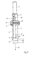
- the segments 3 Due to their resilient design, the segments 3 always endeavor to assume the starting position shown in FIG. 1, which forms the sleeve-like basic shape of the tool body 2.
- the spring force determining the starting position can advantageously be reinforced by an annular spring 11 encompassing the tool body 2.
- the tool body 2 consists of three resilient segments 3; however, the number of segments 3 to be provided is freely selectable.
- cutting elements 12 are arranged, which extend in the circumferential direction and each form the front end of a segment 3.
- the cutting parts 12 have an axial working surface 5 with radial cutting edges 6, the working surface of the cutting part forming the front axial working surface 5 of the tool body 2.
- the working surface 5 assumes a slightly V-shaped position in relation to the expanding mandrel during the spreading, as a result of which an axial force applied to the tool body 2 attempts the oblique Cancel employment.
- the segments 3 are pressed firmly against the expanding mandrel during the operation, namely during drilling or impact drilling.
- the cutting parts 12 are advantageously made of hard metal, ceramic or similar materials and soldered or glued to the free ends of the segments 3. It may also be advantageous to clamp or clamp the cutting parts 12 at the free ends of the segments, so that the cutting parts 12 are easily interchangeable.
- the cutting parts 12 are formed in one piece with the segments 3, so that connection problems between the cutting parts 12 and the segments 3 do not occur.
- Radially aligned cutting teeth 14 are advantageously arranged on the working surface 5 of the cutting elements, as a result of which rapid propulsion is ensured even in extremely hard materials.
- An expanding mandrel 13 lies with its bolt 4 axially displaceably in the tool body 2, a radially projecting pin 9 fixed in the bolt 4 coming to rest in the longitudinal slot 10 of the tool body 2.
- the longitudinal slots 10 are tapered at their open end 16, the pin 9 advantageously having a diameter corresponding approximately to the width of the longitudinal slot 10.
- the free end 16 is expanded to replace a expanding mandrel 13 over the diameter of the pin 9, so that the expanding mandrel 13 can be removed axially.
- the bolt 4 projects out of the tool body 2 with an expansion cone 18 attached to its end.
- the expanding cone 18 is extended by a guide cylinder 17, which essentially corresponds to the diameter of the basic bore already introduced, so that the tool body is centered in the basic bore and the drilling tool can be guided precisely into the working position in the borehole.
- the guide cylinder 17 advantageously has a length such that it still protrudes out of the tool body 2 when the expanding mandrel 13 is retracted to ensure proper centering even after the tool body has been spread open.
- the maximum spread position of the tool body 2- is advantageously limited by a stop 8, which is formed by the end of the bolt 4 lying in the tool body.
- the stop 8 comes into contact with the bottom 20 of the tool body 2 and thus limits the axial displacement path of the expanding mandrel 13 (FIG. 5).
- the shape of the expansion cone 18 determines the final shape of the base bore to be expanded or the intended undercut.
- the outer contour 7a, 7b, 7c of the expanding mandrel 13 corresponds to the section through the expanded basic bore 7'a, 7'b, 7'c. 4c, the inner contour 22 of the tool body 2a is adapted to the outer contour 7c.
- the cutting parts 12 will return to the original diameter in accordance with the starting position when the bottom of the borehole 23 is reached, so that the tool can be withdrawn from the borehole immediately after the operation has ended.
- the tool body is provided with a ring 19 according to FIG. 5, which is positively connected to the expanding mandrel 13 via a pin 9.
- the fully assembled tool is shown in Fig. 5.
- the tool shank 1 is coupled to a rotary drive and the guide cylinder 17 is inserted into the prefabricated borehole (not shown).
- the axial end face which is advantageously equipped with cutting teeth 14 according to FIG. 3, penetrates the material in a rotating or rotating manner. If the guide cylinder 17 comes into contact with the base of the bore, the segments 3 are spread radially outwards when sliding onto the expanding cone 18, so that the work surface 5 with the cutting edges 6 and the cutting teeth 14, with a rotary or rotational impact, produces an undercut corresponding to the expanding cone 18 .
- the expanding mandrel 13 When the drilling tool is withdrawn, the expanding mandrel 13, due to the spring action of the segments 3 and possibly an arranged spring ring 11, experiences an axial force directed in the working direction 21, which causes the expanding mandrel 17 to exit the tool body 2 again in its starting position and the tool body 2 has its tubular basic shape again.
- the cutting parts now again form an almost complete circular ring.
- the expanding mandrel 13 is designed with an outer contour 7a or 7b according to FIG. 4a or FIG. 4b, the expanding mandrel can be mechanically struck by the hammer blows of the drive machine, e.g. B. a rotary hammer, return to the tool end 1 with reduced contact pressure on the cutting parts 12 in its starting position.
- the bolt 4 is acted upon by a spring 15 in its initial position, thereby ensuring a safe return.
- the spring 15 is advantageously between the stop 8 and the bottom 20 in the tool body 2 (Fig. 5).
- the ring 19 lies with radial play 24 on the tool body, so that the tool can spread without the ring preventing it or the ring jamming.
- the position of the ring 19 is determined by the positively engaging pin 9.
- the drilling tool according to the invention consists of only a few parts and is simple and compact. It is inexpensive and ensures a long service life.
- a major advantage of the invention is that the tool for machining hard, inhomogeneous materials such as concrete can be used in a rotational manner since the flat cutting parts 12 cannot hook.
- the tool according to the invention operates largely trouble-free, since the hooking of the cutting edges occurring with single-edged tools is avoided when changing from binding agent to individual, hard aggregates.
- the tool according to the invention can also be used in reinforced concrete.
- To prepare an undercut a hole corresponding to the maximum outside diameter of the expanding mandrel 13 is machined, into which the head of the expanding mandrel is inserted.
- the cutting parts of the tool according to the invention work axially against the concrete, the cutting parts 12 cutting the reinforcements occurring in their surroundings.
Landscapes
- Engineering & Computer Science (AREA)
- Mechanical Engineering (AREA)
- Processing Of Stones Or Stones Resemblance Materials (AREA)
- Drilling Tools (AREA)
Applications Claiming Priority (2)
| Application Number | Priority Date | Filing Date | Title |
|---|---|---|---|
| DE3126472A DE3126472A1 (de) | 1981-07-04 | 1981-07-04 | Bohrwerkzeug zur radialen erweiterung einer zylindrischen grundbohrung |
| DE3126472 | 1981-07-04 |
Publications (2)
| Publication Number | Publication Date |
|---|---|
| EP0069276A2 true EP0069276A2 (fr) | 1983-01-12 |
| EP0069276A3 EP0069276A3 (fr) | 1984-05-30 |
Family
ID=6136141
Family Applications (1)
| Application Number | Title | Priority Date | Filing Date |
|---|---|---|---|
| EP82105502A Withdrawn EP0069276A3 (fr) | 1981-07-04 | 1982-06-23 | Outil de perçage pour élargir radialement un trou cylindrique |
Country Status (4)
| Country | Link |
|---|---|
| US (1) | US4446934A (fr) |
| EP (1) | EP0069276A3 (fr) |
| CA (1) | CA1163986A (fr) |
| DE (1) | DE3126472A1 (fr) |
Cited By (3)
| Publication number | Priority date | Publication date | Assignee | Title |
|---|---|---|---|---|
| FR2611829A1 (fr) * | 1987-03-03 | 1988-09-09 | Campenon Bernard Btp | Procede et dispositif pour realiser un ancrage dans un massif |
| EP0795368A3 (fr) * | 1996-03-13 | 1998-04-08 | Kabushiki Kaisha Miyanaga | Appareil à forer un trou avec chambrage |
| US5810523A (en) * | 1995-02-28 | 1998-09-22 | Kabushiki Kaisha Miyanaga | Apparatus for drilling a hole having an undercut space |
Families Citing this family (7)
| Publication number | Priority date | Publication date | Assignee | Title |
|---|---|---|---|---|
| US4635737A (en) * | 1984-03-08 | 1987-01-13 | Kabushiki Kaishi Miyanaga | Undercutting drill |
| DE3803708A1 (de) * | 1988-02-08 | 1989-08-17 | Fischer Artur Werke Gmbh | Montagevorrichtung fuer schlagbohrmaschinen |
| DE19934430A1 (de) * | 1999-07-22 | 2001-01-25 | Hilti Ag | Bohrwerkzeug |
| US6398634B1 (en) | 2000-09-08 | 2002-06-04 | William P. Gundy | Hole roughening device and method |
| DE10311079A1 (de) * | 2003-03-13 | 2004-09-30 | Powers Fasteners Europe Bv | Bohrvorrichtung |
| DE102014003721A1 (de) * | 2014-03-18 | 2015-09-24 | Karl Storz Gmbh & Co. Kg | Werkzeug und Verfahren zum Erzeugen eines Hinterschnitts in einem Knochen |
| JP6651418B2 (ja) * | 2016-07-07 | 2020-02-19 | 株式会社ミヤナガ | 拡径孔部の穿孔装置 |
Family Cites Families (10)
| Publication number | Priority date | Publication date | Assignee | Title |
|---|---|---|---|---|
| US299991A (en) * | 1884-06-10 | William h | ||
| US833240A (en) * | 1904-09-12 | 1906-10-16 | William Aikman Jr | Reamer. |
| US1244992A (en) * | 1915-09-14 | 1917-10-30 | Joseph Lee | Expansion-bolt. |
| US2544444A (en) * | 1947-04-11 | 1951-03-06 | Louis M Clark | Bevel recessing reamer |
| US2559184A (en) * | 1947-11-04 | 1951-07-03 | Matthew S Bencur | Expansible reamer for making dovetail holes |
| US2511650A (en) * | 1948-10-22 | 1950-06-13 | Ernest S Robinson | Expanding reamer |
| US2638327A (en) * | 1950-05-19 | 1953-05-12 | John C Baldwin | Reamer |
| DE2103132A1 (de) * | 1971-01-23 | 1972-08-03 | Brueckl Technik Ges F Tech Erz | Hülse für Selbstbohrdübel und Verfahren zur Herstellung der Hülse |
| JPS5286592A (en) * | 1976-01-14 | 1977-07-19 | Sanki Eng Co Ltd | Tools for use in drilling |
| DE2921696C2 (de) * | 1977-05-26 | 1983-02-24 | Hilti AG, 9494 Schaan | Bohrwerkzeug zum Erweitern von Bohrlöchern |
-
1981
- 1981-07-04 DE DE3126472A patent/DE3126472A1/de not_active Ceased
-
1982
- 1982-06-23 EP EP82105502A patent/EP0069276A3/fr not_active Withdrawn
- 1982-06-23 US US06/391,160 patent/US4446934A/en not_active Expired - Fee Related
- 1982-07-02 CA CA000406471A patent/CA1163986A/fr not_active Expired
Cited By (3)
| Publication number | Priority date | Publication date | Assignee | Title |
|---|---|---|---|---|
| FR2611829A1 (fr) * | 1987-03-03 | 1988-09-09 | Campenon Bernard Btp | Procede et dispositif pour realiser un ancrage dans un massif |
| US5810523A (en) * | 1995-02-28 | 1998-09-22 | Kabushiki Kaisha Miyanaga | Apparatus for drilling a hole having an undercut space |
| EP0795368A3 (fr) * | 1996-03-13 | 1998-04-08 | Kabushiki Kaisha Miyanaga | Appareil à forer un trou avec chambrage |
Also Published As
| Publication number | Publication date |
|---|---|
| CA1163986A (fr) | 1984-03-20 |
| US4446934A (en) | 1984-05-08 |
| DE3126472A1 (de) | 1983-01-20 |
| EP0069276A3 (fr) | 1984-05-30 |
Similar Documents
| Publication | Publication Date | Title |
|---|---|---|
| DE3932660C2 (de) | Schlagbohrmaschine mit mechanischer Schlagübertragung | |
| EP0878261B1 (fr) | Outil de forage | |
| DE2700700C3 (de) | Bohrwerkzeug | |
| EP0732164B1 (fr) | Outil de perçage, en particulier pour le perçage par percussion de la pierre | |
| WO2004108350A1 (fr) | Machine-outil a main | |
| DE2540838C2 (de) | Elektropneumatischer Hammer | |
| AT4227U1 (de) | Bohrer | |
| EP0008622B1 (fr) | Outil de perçage pour la fabrication d'un alésage détalonné | |
| EP0069276A2 (fr) | Outil de perçage pour élargir radialement un trou cylindrique | |
| DE2558842A1 (de) | Selbstgetriebenes pneumatisches rammbohrgeraet, insbesondere fuer erdbohrungen | |
| DE2535066A1 (de) | Verfahren zum spreizdruckfreien setzen von duebeln sowie werkzeug und duebel zur durchfuehrung des verfahrens | |
| DE3338577A1 (de) | Drucklufthammer-bohrvorrichtung | |
| DE2331467B2 (de) | Vorrichtung zum Ausbohren einer Bohrung mit einem zylindrischen und einem konischen Bereich | |
| WO2014090840A1 (fr) | Porte-outil | |
| EP0343653B1 (fr) | Outil à fraiser et procédé pour agrandir des trous de type cylindrique | |
| EP0808696B1 (fr) | Système de fixation et procédé de réalisation de fixations | |
| EP0302202A2 (fr) | Outil pour la pose d'éléments de fixation | |
| DE2652366C2 (de) | Hinterschnitt-Bohrwerkzeug | |
| DE3206678C2 (de) | Bohrwerkzeug zum Erzeugen eines Hinterschnittes in einer in Stein, Mauerwerk o.dgl. vorgebohrten zylindrischen Sacklochbohrung | |
| DE3421287A1 (de) | Futter zur werkzeughalterung in schlagend arbeitenden maschinen | |
| DE2921696C2 (de) | Bohrwerkzeug zum Erweitern von Bohrlöchern | |
| DE69705561T2 (de) | Gerät zum Bohren eines Loches mit Hinterschnitt | |
| DE3136464C2 (de) | Meißel für die Herstellung axial verlaufender Nuten in den Wandungen von Sprengbohrlöchern und Schneideinsatz dafür | |
| CH695787A5 (de) | Gesteinsbohrkopf. | |
| EP0195265B1 (fr) | Outil pour contre-dépouiller des trous |
Legal Events
| Date | Code | Title | Description |
|---|---|---|---|
| PUAI | Public reference made under article 153(3) epc to a published international application that has entered the european phase |
Free format text: ORIGINAL CODE: 0009012 |
|
| AK | Designated contracting states |
Designated state(s): AT BE CH DE FR GB IT LI NL SE |
|
| PUAL | Search report despatched |
Free format text: ORIGINAL CODE: 0009013 |
|
| AK | Designated contracting states |
Designated state(s): AT BE CH DE FR GB IT LI NL SE |
|
| 17P | Request for examination filed |
Effective date: 19840807 |
|
| STAA | Information on the status of an ep patent application or granted ep patent |
Free format text: STATUS: THE APPLICATION HAS BEEN WITHDRAWN |
|
| 18W | Application withdrawn |
Withdrawal date: 19851210 |
|
| RIN1 | Information on inventor provided before grant (corrected) |
Inventor name: MUELLER, NORBERT, DIPL.-ING. |