EP0069404A2 - Wärmetransportvorrichtung die aus einem luftdicht verschlossenen Vakuumrohr besteht - Google Patents
Wärmetransportvorrichtung die aus einem luftdicht verschlossenen Vakuumrohr besteht Download PDFInfo
- Publication number
- EP0069404A2 EP0069404A2 EP82200569A EP82200569A EP0069404A2 EP 0069404 A2 EP0069404 A2 EP 0069404A2 EP 82200569 A EP82200569 A EP 82200569A EP 82200569 A EP82200569 A EP 82200569A EP 0069404 A2 EP0069404 A2 EP 0069404A2
- Authority
- EP
- European Patent Office
- Prior art keywords
- heat transport
- hydroxide
- water
- tube
- transport device
- Prior art date
- Legal status (The legal status is an assumption and is not a legal conclusion. Google has not performed a legal analysis and makes no representation as to the accuracy of the status listed.)
- Granted
Links
- XLYOFNOQVPJJNP-UHFFFAOYSA-N water Substances O XLYOFNOQVPJJNP-UHFFFAOYSA-N 0.000 claims abstract description 28
- XLYOFNOQVPJJNP-UHFFFAOYSA-M hydroxide Chemical compound [OH-] XLYOFNOQVPJJNP-UHFFFAOYSA-M 0.000 claims abstract description 22
- 239000006163 transport media Substances 0.000 claims abstract description 15
- 229910052788 barium Inorganic materials 0.000 claims abstract description 14
- 239000011575 calcium Substances 0.000 claims abstract description 14
- 229910052791 calcium Inorganic materials 0.000 claims abstract description 13
- 229910052712 strontium Inorganic materials 0.000 claims abstract description 13
- 229910052751 metal Inorganic materials 0.000 claims abstract description 8
- 239000002184 metal Substances 0.000 claims abstract description 8
- 150000002739 metals Chemical class 0.000 claims abstract description 8
- OYPRJOBELJOOCE-UHFFFAOYSA-N Calcium Chemical compound [Ca] OYPRJOBELJOOCE-UHFFFAOYSA-N 0.000 claims abstract description 5
- DSAJWYNOEDNPEQ-UHFFFAOYSA-N barium atom Chemical compound [Ba] DSAJWYNOEDNPEQ-UHFFFAOYSA-N 0.000 claims abstract description 5
- CIOAGBVUUVVLOB-UHFFFAOYSA-N strontium atom Chemical compound [Sr] CIOAGBVUUVVLOB-UHFFFAOYSA-N 0.000 claims abstract description 4
- 150000004649 carbonic acid derivatives Chemical class 0.000 claims description 7
- BVKZGUZCCUSVTD-UHFFFAOYSA-L Carbonate Chemical compound [O-]C([O-])=O BVKZGUZCCUSVTD-UHFFFAOYSA-L 0.000 claims description 5
- HEMHJVSKTPXQMS-UHFFFAOYSA-M Sodium hydroxide Chemical compound [OH-].[Na+] HEMHJVSKTPXQMS-UHFFFAOYSA-M 0.000 description 11
- 238000007710 freezing Methods 0.000 description 11
- 230000008014 freezing Effects 0.000 description 11
- 239000007789 gas Substances 0.000 description 10
- 238000009835 boiling Methods 0.000 description 7
- KWYUFKZDYYNOTN-UHFFFAOYSA-M Potassium hydroxide Chemical compound [OH-].[K+] KWYUFKZDYYNOTN-UHFFFAOYSA-M 0.000 description 6
- RQPZNWPYLFFXCP-UHFFFAOYSA-L barium dihydroxide Chemical compound [OH-].[OH-].[Ba+2] RQPZNWPYLFFXCP-UHFFFAOYSA-L 0.000 description 5
- 229910052700 potassium Inorganic materials 0.000 description 5
- 229910052708 sodium Inorganic materials 0.000 description 5
- 239000011734 sodium Substances 0.000 description 5
- 229910001863 barium hydroxide Inorganic materials 0.000 description 4
- 150000004679 hydroxides Chemical class 0.000 description 4
- 239000000203 mixture Substances 0.000 description 4
- AYJRCSIUFZENHW-UHFFFAOYSA-L barium carbonate Chemical compound [Ba+2].[O-]C([O-])=O AYJRCSIUFZENHW-UHFFFAOYSA-L 0.000 description 2
- TZCXTZWJZNENPQ-UHFFFAOYSA-L barium sulfate Chemical compound [Ba+2].[O-]S([O-])(=O)=O TZCXTZWJZNENPQ-UHFFFAOYSA-L 0.000 description 2
- 229910052601 baryte Inorganic materials 0.000 description 2
- 239000010428 baryte Substances 0.000 description 2
- 239000013078 crystal Substances 0.000 description 2
- 230000000694 effects Effects 0.000 description 2
- 239000002609 medium Substances 0.000 description 2
- 239000000126 substance Substances 0.000 description 2
- RYGMFSIKBFXOCR-UHFFFAOYSA-N Copper Chemical compound [Cu] RYGMFSIKBFXOCR-UHFFFAOYSA-N 0.000 description 1
- DGAQECJNVWCQMB-PUAWFVPOSA-M Ilexoside XXIX Chemical compound C[C@@H]1CC[C@@]2(CC[C@@]3(C(=CC[C@H]4[C@]3(CC[C@@H]5[C@@]4(CC[C@@H](C5(C)C)OS(=O)(=O)[O-])C)C)[C@@H]2[C@]1(C)O)C)C(=O)O[C@H]6[C@@H]([C@H]([C@@H]([C@H](O6)CO)O)O)O.[Na+] DGAQECJNVWCQMB-PUAWFVPOSA-M 0.000 description 1
- 239000006096 absorbing agent Substances 0.000 description 1
- 230000002411 adverse Effects 0.000 description 1
- 239000000956 alloy Substances 0.000 description 1
- 229910045601 alloy Inorganic materials 0.000 description 1
- 230000015572 biosynthetic process Effects 0.000 description 1
- 229910001861 calcium hydroxide Inorganic materials 0.000 description 1
- 238000006243 chemical reaction Methods 0.000 description 1
- 229910052802 copper Inorganic materials 0.000 description 1
- 239000010949 copper Substances 0.000 description 1
- 230000005484 gravity Effects 0.000 description 1
- 238000005461 lubrication Methods 0.000 description 1
- 238000013021 overheating Methods 0.000 description 1
- 229910052709 silver Inorganic materials 0.000 description 1
- 239000004332 silver Substances 0.000 description 1
- 239000007787 solid Substances 0.000 description 1
- UUCCCPNEFXQJEL-UHFFFAOYSA-L strontium dihydroxide Chemical compound [OH-].[OH-].[Sr+2] UUCCCPNEFXQJEL-UHFFFAOYSA-L 0.000 description 1
- 229910001866 strontium hydroxide Inorganic materials 0.000 description 1
Images
Classifications
-
- F—MECHANICAL ENGINEERING; LIGHTING; HEATING; WEAPONS; BLASTING
- F28—HEAT EXCHANGE IN GENERAL
- F28D—HEAT-EXCHANGE APPARATUS, NOT PROVIDED FOR IN ANOTHER SUBCLASS, IN WHICH THE HEAT-EXCHANGE MEDIA DO NOT COME INTO DIRECT CONTACT
- F28D15/00—Heat-exchange apparatus with the intermediate heat-transfer medium in closed tubes passing into or through the conduit walls ; Heat-exchange apparatus employing intermediate heat-transfer medium or bodies
- F28D15/02—Heat-exchange apparatus with the intermediate heat-transfer medium in closed tubes passing into or through the conduit walls ; Heat-exchange apparatus employing intermediate heat-transfer medium or bodies in which the medium condenses and evaporates, e.g. heat pipes
-
- C—CHEMISTRY; METALLURGY
- C09—DYES; PAINTS; POLISHES; NATURAL RESINS; ADHESIVES; COMPOSITIONS NOT OTHERWISE PROVIDED FOR; APPLICATIONS OF MATERIALS NOT OTHERWISE PROVIDED FOR
- C09K—MATERIALS FOR MISCELLANEOUS APPLICATIONS, NOT PROVIDED FOR ELSEWHERE
- C09K5/00—Heat-transfer, heat-exchange or heat-storage materials, e.g. refrigerants; Materials for the production of heat or cold by chemical reactions other than by combustion
- C09K5/08—Materials not undergoing a change of physical state when used
-
- F—MECHANICAL ENGINEERING; LIGHTING; HEATING; WEAPONS; BLASTING
- F24—HEATING; RANGES; VENTILATING
- F24S—SOLAR HEAT COLLECTORS; SOLAR HEAT SYSTEMS
- F24S80/00—Details, accessories or component parts of solar heat collectors not provided for in groups F24S10/00-F24S70/00
- F24S80/20—Working fluids specially adapted for solar heat collectors
-
- Y—GENERAL TAGGING OF NEW TECHNOLOGICAL DEVELOPMENTS; GENERAL TAGGING OF CROSS-SECTIONAL TECHNOLOGIES SPANNING OVER SEVERAL SECTIONS OF THE IPC; TECHNICAL SUBJECTS COVERED BY FORMER USPC CROSS-REFERENCE ART COLLECTIONS [XRACs] AND DIGESTS
- Y02—TECHNOLOGIES OR APPLICATIONS FOR MITIGATION OR ADAPTATION AGAINST CLIMATE CHANGE
- Y02E—REDUCTION OF GREENHOUSE GAS [GHG] EMISSIONS, RELATED TO ENERGY GENERATION, TRANSMISSION OR DISTRIBUTION
- Y02E10/00—Energy generation through renewable energy sources
- Y02E10/40—Solar thermal energy, e.g. solar towers
Definitions
- the invention relates to a heat transport device, comprising a sealed and evacuated tube which contains a heat transport medium which evaporates in a heated section of the tube during operation and which condenses in a cooled section of the tube, the heat transport medium being water which contains a small amount of a hydroxide which is still sufficiently soluble in water at O O C.
- a heat transport device of the kind set forth is known from "Proceedings of the 13th Intersociety Energy Conversion Engineering Conference", August 20-25, 1978, pages 1050-1054.
- This kind of heat transport device is particularly suitable for use in solar collectors for transporting the heat collected by the absorber to a medium to be heated.
- a second drawback consists in that delay of boiling occurs at lower operating temperatures, i.e. the heat transport medium sharts to boil only at a temperature which is substantially higher than the boiling point associated with the pressure prevailing in the tube. This has an adverse effect on the operation and may even cause overheating of some parts of the device in which the heat transport device is incorporated.
- a third drawback consists in that at temperatures which are normal, for example, for solar collectors small amounts of residual gases occupy a large volume due to the low pressure in the tube. Such residual gases collect in the condenser and exclude part of the condenser surface area from the transfer of heat.
- the first drawback i.e. the risk of freezing
- suitably soluble chemicals for example, in practice it is known to add a small amount of sodium hydroxide to the water. A lubrication effect from concentrated dissolved substance then occurs between the ice crystals formed, so that the ice crystals can slide along one another and no solid plugs are formed.
- the device in accordance with the invention is characterized in that the hydroxide added to the water is at least partly formed by a hydroxide of one of the metals with insoluble carbonates which are thermally stable at the elevated temperatures liable to occur in solar collectors.
- the hydroxide is formed at least partly by a hydroxide of Ba, Ca or Sr.
- Hydroxides of the metals Na, K and Ba offer a suitable protection against breaking due to freezing, because these hydroxides are still sufficiently soluble in water at O°C.
- such hydroxides always contain a small amount of carbonates.
- the carbonates of Na and K are not thermally stable at the elevated temperatures liable to occur in solar collectors (from 200 to 300°C) and give off C0 2 at these temperatures. As has already been explained, this residual gas disturbs the operation of the device. A very long period of time is required before the CO 2 formed is dissolved again in the hydroxide.
- barium hydroxide is added to the water, because barium carbonate is thermally stable at the elevated temperatures liable to occur in solar collectors, so that no CO 2 is formed. Furthermore barium hydroxide is still sufficiently soluble in water at O O C in order to provide protection against breaking due to freezing.
- the residual gas problem can be eliminated and a protection against breaking due to freezing can alternatively be achieved by adding to the water mainly Na or K hydroxide and also a small amount of Ba, Ca or Sr hydroxide. Should any CO 2 be formed, it will be bound by the Ba, Ca or Sr and a thermally stable and insoluble carbonate will be formed. This carbonate does not disturb the operation of the device.
- a mixture of 0.1 M sodium hydroxide and a small amount of Ba, Ca or Sr hydroxide offers excellent results in practice.
- a preferred embodiment of the device in accordance with the invention is characterized in that the heat transport medium contains a very small amount of carbonate of one or more of the metals barium, calcium or strontium.
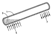
- the drawing shows ,by way of example, a diagrammatic sectional view of a heat transport device.
- the heat transport device comprises a tube 1.
- the tube 1 contains a heat transport medium 3.
- the inner wall may comprise a porous layer, for example, a layer of gauze so that the condensate is returned to the section 5 under the influence of the capillary forces in the layer.
- the tube itself is made of copper or silver or alloys thereof with other metals.
- the heat transport medium 3 is a mixture of water and a small amount of turbid barite water.
- a heat transport device is thus obtained which offers the described advantages and which, moreover, is not more expensive than the known devices.
- an amount of sodium or potassium hydroxide (0.1 M) and a small amount of barium, calcium or strontium hydroxide may be added to the water.
- an adequate amount of dissolved Na, K or Ba hydroxide or mixtures thereof must be present in the water.
- an adequate amount of dissolved Na, K or Ba hydroxide or mixtures thereof must be present in the water.
- At least a small amount of Ba, Ca or Sr hydroxide must be present. Any residual gases formed are then bound to form insoluble and thermally stable car- b o nates.
- a small amount of Ba, Ca or Sr carbonate or mixtures thereof must be present in the water.
Landscapes
- Engineering & Computer Science (AREA)
- Chemical & Material Sciences (AREA)
- Physics & Mathematics (AREA)
- Thermal Sciences (AREA)
- General Engineering & Computer Science (AREA)
- Mechanical Engineering (AREA)
- Life Sciences & Earth Sciences (AREA)
- Sustainable Development (AREA)
- Combustion & Propulsion (AREA)
- Chemical Kinetics & Catalysis (AREA)
- Materials Engineering (AREA)
- Organic Chemistry (AREA)
- Sustainable Energy (AREA)
- Compounds Of Alkaline-Earth Elements, Aluminum Or Rare-Earth Metals (AREA)
Applications Claiming Priority (2)
| Application Number | Priority Date | Filing Date | Title |
|---|---|---|---|
| NL8102467 | 1981-05-20 | ||
| NL8102467A NL8102467A (nl) | 1981-05-20 | 1981-05-20 | Warmtetransportinrichting met een gesloten en geevacueerde buis. |
Publications (3)
| Publication Number | Publication Date |
|---|---|
| EP0069404A2 true EP0069404A2 (de) | 1983-01-12 |
| EP0069404A3 EP0069404A3 (en) | 1983-02-09 |
| EP0069404B1 EP0069404B1 (de) | 1984-08-01 |
Family
ID=19837530
Family Applications (1)
| Application Number | Title | Priority Date | Filing Date |
|---|---|---|---|
| EP82200569A Expired EP0069404B1 (de) | 1981-05-20 | 1982-05-11 | Wärmetransportvorrichtung die aus einem luftdicht verschlossenen Vakuumrohr besteht |
Country Status (5)
| Country | Link |
|---|---|
| EP (1) | EP0069404B1 (de) |
| JP (1) | JPS57196047A (de) |
| AU (1) | AU553284B2 (de) |
| DE (1) | DE3260495D1 (de) |
| NL (1) | NL8102467A (de) |
Cited By (2)
| Publication number | Priority date | Publication date | Assignee | Title |
|---|---|---|---|---|
| EP0231189B1 (de) * | 1984-11-01 | 1990-06-06 | MOORE, Barrie Peter | Dacheinrichtungen |
| FR2947280A1 (fr) * | 2009-06-30 | 2010-12-31 | Omya Development Ag | Fluide caloporteur |
Families Citing this family (2)
| Publication number | Priority date | Publication date | Assignee | Title |
|---|---|---|---|---|
| DE3760977D1 (en) * | 1986-04-23 | 1989-12-14 | Showa Aluminum Corp | Heat pipe |
| JP7461777B2 (ja) * | 2020-03-31 | 2024-04-04 | 宇部マテリアルズ株式会社 | 沸騰冷却用作動液、それを用いた沸騰冷却装置および沸騰冷却方法 |
Family Cites Families (3)
| Publication number | Priority date | Publication date | Assignee | Title |
|---|---|---|---|---|
| US3738421A (en) * | 1971-06-11 | 1973-06-12 | R Moore | Heatronic capacitor |
| DE2631320C2 (de) * | 1976-07-12 | 1983-05-11 | Alefeld, Georg, Prof.Dr., 8000 München | Verfahren zur Speicherung von Wärme |
| US4063419A (en) * | 1976-11-12 | 1977-12-20 | Garrett Donald E | Energy production from solar ponds |
-
1981
- 1981-05-20 NL NL8102467A patent/NL8102467A/nl not_active Application Discontinuation
-
1982
- 1982-05-11 EP EP82200569A patent/EP0069404B1/de not_active Expired
- 1982-05-11 DE DE8282200569T patent/DE3260495D1/de not_active Expired
- 1982-05-17 JP JP57081695A patent/JPS57196047A/ja active Pending
- 1982-05-18 AU AU83799/82A patent/AU553284B2/en not_active Ceased
Cited By (5)
| Publication number | Priority date | Publication date | Assignee | Title |
|---|---|---|---|---|
| EP0231189B1 (de) * | 1984-11-01 | 1990-06-06 | MOORE, Barrie Peter | Dacheinrichtungen |
| FR2947280A1 (fr) * | 2009-06-30 | 2010-12-31 | Omya Development Ag | Fluide caloporteur |
| WO2011001072A1 (fr) * | 2009-06-30 | 2011-01-06 | Omya Development Ag | Fluide caloporteur |
| RU2515289C2 (ru) * | 2009-06-30 | 2014-05-10 | Омиа Интернэшнл Аг | Охладитель |
| US9080090B2 (en) | 2009-06-30 | 2015-07-14 | Omya International Ag | Specific fluid for converting light radiation to heat |
Also Published As
| Publication number | Publication date |
|---|---|
| EP0069404A3 (en) | 1983-02-09 |
| AU8379982A (en) | 1982-11-25 |
| DE3260495D1 (en) | 1984-09-06 |
| JPS57196047A (en) | 1982-12-01 |
| EP0069404B1 (de) | 1984-08-01 |
| AU553284B2 (en) | 1986-07-10 |
| NL8102467A (nl) | 1982-12-16 |
Similar Documents
| Publication | Publication Date | Title |
|---|---|---|
| JP5021597B2 (ja) | 蓄熱方法および蓄熱システム | |
| AU696194B2 (en) | Passive cooling of enclosures using heat pipes | |
| KR910008358A (ko) | 비등냉각장치 | |
| US4315498A (en) | Solar collector | |
| EP0069404B1 (de) | Wärmetransportvorrichtung die aus einem luftdicht verschlossenen Vakuumrohr besteht | |
| US4454724A (en) | Aqueous absorbent for absorption cycle heat pump | |
| KR20110106942A (ko) | 비등 냉각 장치 | |
| EP0507775A1 (de) | Mehrstufige trocknende kühlanlage | |
| KR880003214A (ko) | 수화된 브롬화칼슘 가역성 상변화 조성물 | |
| US3316728A (en) | Absorption refrigeration systems | |
| US4857222A (en) | Absorption type refrigerator and absorbing solution therefor | |
| US4018694A (en) | Absorption refrigerant composition | |
| KR850000506A (ko) | 에너지 저장을 위한 가역성 상이전 조성물 | |
| GB2213244A (en) | Refrigerating appliances | |
| JPS61240094A (ja) | ヒ−トパイプ | |
| US4175613A (en) | Method of storing energy | |
| JPS5864486A (ja) | 熱交換装置 | |
| EP0066315B1 (de) | Wärmetransportapparat für Sonnenkollektor | |
| US3553136A (en) | Reduction of vapor pressure in absorption type refrigeration cycle | |
| JPS5774549A (en) | Heat collector | |
| UTAKA et al. | A Method of Efficient Ice Cool Energy Storage Using Heat Transfer of Direct Contact Phase Change Between Working Medium and PCM in an Enclosure | |
| US2055856A (en) | Absorption type refrigerating system | |
| US3678699A (en) | Absorption | |
| SU960503A1 (ru) | Устройство дл получени низких температур | |
| SU892181A1 (ru) | Теплова труба |
Legal Events
| Date | Code | Title | Description |
|---|---|---|---|
| PUAI | Public reference made under article 153(3) epc to a published international application that has entered the european phase |
Free format text: ORIGINAL CODE: 0009012 |
|
| PUAL | Search report despatched |
Free format text: ORIGINAL CODE: 0009013 |
|
| 17P | Request for examination filed |
Effective date: 19820511 |
|
| AK | Designated contracting states |
Designated state(s): DE FR GB IT NL SE |
|
| AK | Designated contracting states |
Designated state(s): DE FR GB IT NL SE |
|
| ITF | It: translation for a ep patent filed | ||
| GRAA | (expected) grant |
Free format text: ORIGINAL CODE: 0009210 |
|
| AK | Designated contracting states |
Designated state(s): DE FR GB IT NL SE |
|
| REF | Corresponds to: |
Ref document number: 3260495 Country of ref document: DE Date of ref document: 19840906 |
|
| ET | Fr: translation filed | ||
| PLBE | No opposition filed within time limit |
Free format text: ORIGINAL CODE: 0009261 |
|
| STAA | Information on the status of an ep patent application or granted ep patent |
Free format text: STATUS: NO OPPOSITION FILED WITHIN TIME LIMIT |
|
| 26N | No opposition filed | ||
| PGFP | Annual fee paid to national office [announced via postgrant information from national office to epo] |
Ref country code: GB Payment date: 19900430 Year of fee payment: 9 |
|
| PGFP | Annual fee paid to national office [announced via postgrant information from national office to epo] |
Ref country code: SE Payment date: 19900522 Year of fee payment: 9 Ref country code: FR Payment date: 19900522 Year of fee payment: 9 |
|
| ITTA | It: last paid annual fee | ||
| PGFP | Annual fee paid to national office [announced via postgrant information from national office to epo] |
Ref country code: NL Payment date: 19900531 Year of fee payment: 9 |
|
| PGFP | Annual fee paid to national office [announced via postgrant information from national office to epo] |
Ref country code: DE Payment date: 19900725 Year of fee payment: 9 |
|
| PG25 | Lapsed in a contracting state [announced via postgrant information from national office to epo] |
Ref country code: GB Effective date: 19910511 |
|
| PG25 | Lapsed in a contracting state [announced via postgrant information from national office to epo] |
Ref country code: SE Effective date: 19910512 |
|
| PG25 | Lapsed in a contracting state [announced via postgrant information from national office to epo] |
Ref country code: NL Effective date: 19911201 |
|
| GBPC | Gb: european patent ceased through non-payment of renewal fee | ||
| NLV4 | Nl: lapsed or anulled due to non-payment of the annual fee | ||
| PG25 | Lapsed in a contracting state [announced via postgrant information from national office to epo] |
Ref country code: FR Effective date: 19920131 |
|
| PG25 | Lapsed in a contracting state [announced via postgrant information from national office to epo] |
Ref country code: DE Effective date: 19920303 |
|
| REG | Reference to a national code |
Ref country code: FR Ref legal event code: ST |
|
| EUG | Se: european patent has lapsed |
Ref document number: 82200569.0 Effective date: 19911209 |