EP0069438B1 - Système de multitraitement, système et méthode pour l'intercommunication entre processeurs, système pour le transfert des données, système pour contrôler le routage des messages et arrangement pour déterminer un état global d'être prêt du système - Google Patents
Système de multitraitement, système et méthode pour l'intercommunication entre processeurs, système pour le transfert des données, système pour contrôler le routage des messages et arrangement pour déterminer un état global d'être prêt du système Download PDFInfo
- Publication number
- EP0069438B1 EP0069438B1 EP82301742A EP82301742A EP0069438B1 EP 0069438 B1 EP0069438 B1 EP 0069438B1 EP 82301742 A EP82301742 A EP 82301742A EP 82301742 A EP82301742 A EP 82301742A EP 0069438 B1 EP0069438 B1 EP 0069438B1
- Authority
- EP
- European Patent Office
- Prior art keywords
- processor
- messages
- message
- transaction
- network
- Prior art date
- Legal status (The legal status is an assumption and is not a legal conclusion. Google has not performed a legal analysis and makes no representation as to the accuracy of the status listed.)
- Expired
Links
Images








Classifications
-
- G—PHYSICS
- G06—COMPUTING OR CALCULATING; COUNTING
- G06F—ELECTRIC DIGITAL DATA PROCESSING
- G06F15/00—Digital computers in general; Data processing equipment in general
- G06F15/16—Combinations of two or more digital computers each having at least an arithmetic unit, a program unit and a register, e.g. for a simultaneous processing of several programs
- G06F15/163—Interprocessor communication
- G06F15/173—Interprocessor communication using an interconnection network, e.g. matrix, shuffle, pyramid, star, snowflake
- G06F15/17356—Indirect interconnection networks
- G06F15/17368—Indirect interconnection networks non hierarchical topologies
-
- H—ELECTRICITY
- H04—ELECTRIC COMMUNICATION TECHNIQUE
- H04L—TRANSMISSION OF DIGITAL INFORMATION, e.g. TELEGRAPHIC COMMUNICATION
- H04L69/00—Network arrangements, protocols or services independent of the application payload and not provided for in the other groups of this subclass
Definitions
- the concurrently filed application No: 82301726.4 (NECHES et al.) describes and claims improved data processing systems and method which in substantial measure are based upon and emanate from a novel active logic network.
- the active logic network is so configured and arranged that it merges a number of concurrent, competing message packets from different sources during message transfer on the network.
- a converging progression of pair comparisons is continued without interruption until a winning message packet is determined, and then distributed in the opposite direction to all sources.
- a coherent priority scheme is employed that encompasses a variety of message types such that responses, status and control messages can be intermingled in the transmissions. In consequence of these and other factors, the ratio of data message traffic to overhead traffic on the network is significantly increased over prior systems.
- the system is broadly expandable without a concomitant increase in overhead systems or software.
- Use of these techniques greatly facilitates the ways in which multiple message sources, such as an array of data processors may work cooperatively toward a common purpose.
- the copending application further discloses and claims improved multiprocessor systems, including relational data base machines, arranged both as backend processors and stand alone systems.
- a versatile multiprocessor must be able to distribute subtasks in a number of ways, ascertain the status of the processors performing the subtasks, merge and sort messages, correct and revise data, and ascertain when and how resources have changed (as when processors fail or come on line). Performance of such functions has heretofore entailed the use of excessive overhead software and hardware.
- a multiprocessor system such as a data base machine
- route messages between processors so as to select an individual destination processor, or select a class of processors, or select the destination not upon a processor identification but instead upon the portion of the data base distributed to that processor, as by a hashing technique.
- a prefatory communication sequence is used, in which a linkage is established between the sending processor and one or more specific receiving processors. Repeated requests and acknowledgments may be needed to establish the linkage, and deadlock conditions that may arise must be overcome by the use of further hardware and software.
- a supervisory control is exercised by one processor or a bus controller, to assure that the transmitting processor is ready to transmit, that the receiving processor or processors are ready to receive, that other processors are blocked out of the linkage and that no extraneous transmissions are generated.
- the commitment to overhead and the intricacies needed to avoid deadlocks require maintenance functions that become disproportionately large as the system is expanded (e.g. to more than 16 processors).
- One objective of the present invention is to make use of the various capabilities of the Neches concept without diminution of the efficiency of the system, requiring additional software, or restricting the capacity for expansion. Another objective is to provide the needed intercommunication versatility in such a way that extremely large numbers of processors (e.g. 1024) can be used in a system without imposing overhead penalties or creating deadlock or lockout possibilities.
- processors e.g. 1024
- Another example of what is required of a modern multi-processor system relates to how the system can assuredly determine the status of the subtasks being performed by one or a number of processors.
- a basic requirement is that there be an ability to interrogate a given processor as to its status, without having the interrogation affect the status or creating ambiguity as to the nature of the response.
- the term "semaphore" has been used in the industry to characterize the function of testing and setting a status indication without interruption.
- the Motorola 16-Bit-microprocessor MC 68000 is an example of a processor having a semaphore facility. Thus the provision of a local semaphore facility is known.
- a typical drawback in prior art multiprocessor systems is the so-called "distributed update" problem, which is the need to update information a copy of which may be stored in each of several processing elements.
- This information may consist of data records or of information used to control the operation of the system such that processing can be initiated, terminated, resumed, suspended, or rolled backwards or forwards without causing any required steps to be erroneously either duplicated or omitted.
- Solutions of the distributed update problem in prior art systems suffer significant limitations. Some consider only two processors at a time. Still others involve protocols of intercommunication which are so complex that they have resisted all efforts to date to prove their correctness in a mathematically rigorous manner.
- EP-A-0 029 502 (Concerning the designated contracting states DE, FR and GB the European patent application 80 106 166.2 published as EP-A-0 029 502 falls within the state of the art as defined by Article 54(3) and 54(4) EPC).
- a multiprocessor system of the type in which individual processor modules contend with other processor modules for intercommunication between processors via a bidirectional intercommunication network means including a plurality of decision elements, characterised by:
- a method of intercommunication between processors which must both compete and cooperate in a multiprocessor system via a bidirectional intercommunication network, including the steps of sending messages from the processors into the network and presenting a priority message to all coupled processors simultaneously, characterised by the steps of:
- a system for effecting data transfer between a processor which provides messages including transaction numbers and a bidirectional network which intercouples the processor to other systems characterised by:
- the many message routing, mode control and status indication functions required for a complex and versatile multiprocessor system may be implemented in association with the present invention which enables a unique combination of message organization and traffic controlling interface circuits functioning with the active logic network to be established.
- Message packets which may be of variable lengths, are organized into variable sequences of fields, the field values being selected to have significance in the prioritizing network.
- the interface circuits store incoming and outgoing message packets with bidirectional accessibility and moreover include sections dedicated to destination, status and control functions.
- Particular message fields within a broadcast primary message packet determine, solely by interface operation, whether a message packet is to be accepted by the associated processor, and the multiprocessor mode of operation that is to be used.
- Responses, status and control messages all function within this cooperative format, serving both a prioritizing function and a traffic control or routing function.
- a further feature which may be implemented using the present invention is that transaction identities are included in primary data, status and control messages.
- the local processor can maintain at the interface circuits, accessible to the network, a locally updated indication of the state of readiness of that processor as to the task bearing the transaction identity.
- a distributed update as to the global status of the system can be derived by a single query to all processors. Each responds concurrently with its local status, and the least ready status is accorded highest priority in sorting on the network. Thus a single response from all processors may be merged into one indication of global readiness.
- the message organization incorporates an initial command word, which includes a transaction number for primary, status and control messages, or an originating processor identification for responses.
- the numerical values of the initial portion of the command word, and the transaction number (or originating processor identification) all form a part of the coherent set of priority values such that the network distinguishes between and gives precedence to messages based both upon type and specific data content within the type.
- An optional key field used as a sorting criteria may also be employed in the message.
- the data field which may be of variable length, may initiate with a destination selection word, which by its data content designates a specific individual processor for reception of the message, a process class, or a hashing value related to distributed data storage.
- a high speed random access memory serves as a buffer between the relatively high speed network and the substantially lower speed microprocessor, having individual ports for coupling to both the network and the processor bus.
- a portion of the high speed random access memory includes dedicated sections which may be directly addressed by the destination selection word, enabling a specific processor, process class or hashing value to govern destination selection.
- the high speed random access memory also contains a directory of numerical values representing readiness states for the processor, which the processor may reference to locally update status pertaining to a given transaction number. An inquiry from the network elicits an immediate and unambiguous response as to the local readiness state. The status responses also have predetermined rankings within the priority schedule, and merger of the responses of the network reveals the lowest state of readiness when received by the requesting processor.
- subtasks identified by transaction numbers are distributed as appropriate throughout various individual processors, where the input messages are stored in a circular buffer section in the high speed random access memory. Sequences of output messages available for transmission to the network are assembled by each local processor, the high speed random access memory including a circular output vector section that enables chaining of the output messages together in an ordered sequence.
- each local processor provides a sorted sequence of output message packets pertaining to each transaction number. Single queries suffice to determine the global state of readiness as to the particular task. When all processors are ready, they concurrently and repeatedly attempt to launch their highest priority messages onto the network, which prioritizes them by transferring winning messages in sequence until that transaction number is exhausted, after which the next transaction number may be selected. A transaction number of zero establishes the non-merge mode without any further communication being needed.
- the system provides an integrated, essentially hardware based, mechanism for logical control of locally distributed resources.
- the dedicated buffer system and interrelated message organization perform global semaphore, control and pacing functions within the system.
- the random access memory is not only used in particular ways in receiving and supplying outgoing and incoming messages, but also in assuring that overrun conditions do not occur.
- each group of multiple parallel data lines interconnecting the node elements in the network is associated with a control line, the signal patterns on which vary in accordance with the field groupings, to demarcate transitions between fields and also to characterize the different fields for different types of messages.
- a parity line may also be used, not only to identify parity errors occurring during transfer, at the node elements or at the processors, but also in conjunction with means for forcing a parity error to denote the failure or recovery of a processor in the system. This is a readily achieved but immediately effective means for generating an interrupt indication to denote a change in the global resource.
- the network also includes unidirectional couplings between node elements in the successive tiers, transferring indication of loss of priority from the node at which a determination is made through the successive lower tiers back to the originating processor, which thereupon can terminate transmission for that message packet.
- the bidirectional network and a unique clocking arrangement assure simultaneous broadcasting of a message packet to all processors.
- a high speed clock fed in at the apex of the network is regenerated at each of the active circuit nodes with zero time skew along the network.
- the network may be physically distributed with active circuit elements intercoupled by short path length conductors or by transmission lines in a compact but expandable configuration.
- the system depicted generally in Fig. 1 is illustrative of usage of the concepts of the invention in a data base management application.
- the system is configured for cooperation with one or more host computer systems 10, 12, such as one of the IBM 370 family or DEC PDP-11 family, which advantageously, for purposes of this example, operate with existing and conventional operating system and applications software.
- host computer systems 10, 12 such as one of the IBM 370 family or DEC PDP-11 family, which advantageously, for purposes of this example, operate with existing and conventional operating system and applications software.
- the principal intercommunication networks between the host and the data base computer are referred to as channels while in the DEC terminology the equivalent is referred to as a "UNIBUS" or "MASSBUS" or some other variant.
- the channel or bus is an ohmic or logically passive pathway on which data base tasks and subtasks are presented.
- Fig. 1 shows a backend processor complex in association with host systems 10, 12.
- the system accepts tasks and substasks from the host system, references the appropriate part or parts of an extensive data base storage, and returns appropriate processed or responsive messages in such fashion that no more than menial software management is required of the host systems, irrespective of the configuration of the backend processor complex. Consequently, the user's data base can be structured in a new multiprocessor system in which the data are organized in relational data base files of broadly expandable capacity; expansion can occur without any need to change the operating system or existing applications software resident in the user's host system.
- An example of a stand alone system is described below in conjunction with Fig. 20.
- relational data base management involves an overall function which is divisible into processing tasks that are separable, at least temporarily, because the data entries in storage are not interdependently linked by address pointers. It will also be recognized that many other data processing situations exist in which dynamic subdivision and independent processing of limited or iterative tasks can be used. Thus while this example of the invention is described in terms of the demanding and widely encountered data base management processing problem, the novel methods and implementations disclosed herein are of broad applicability elsewhere as well.
- a large data management system involves both potential advantages and the inherent difficulties when multiple processors are to be used. Vast numbers of entries, ranging into the hundreds of millions, must be held conveniently and rapidly accessible in storage. With the relational data base format, a wide range of data entry and information retrieval functions can be carried out concurrently.
- Integrity therefore implies that a degree of redundancy is required in the data base system, along with data roll back and recovery operations, error detection and correction, and detection of and compensation for changes in status of individual parts of the system.
- the system may have to be used in a number of different specific modes to accomplish these objectives.
- discretionary queries that can be complex in form and to respond if necessary in an interactive fashion. Those who seek access to the system should not, despite the complexity of the query, be required to be experts in the system. Examples of discretionary queries that may be generated pertaining to a large production operation include the following:
- the user seeks to gain an insight into a real problem confronting him profressionally by correlating, in unanticipated ways, information stored in the computer.
- the user's experience with his own problem areas and thus his intuition and imagination permits the non-computer- trained professional to make facile use of a data base system that is capable of handling complex queries.
- the multiprocessor array-In Fig. 1 a typical system in accordance with the invention includes multiple microprocessors of two principal types, herein designated the interface processor (IFP) and the access module processor (AMP).
- IFP interface processor
- AMP access module processor
- a number of access module processors 18-23 inclusive are also incorporated in what may be termed a multiprocessor array.
- array is used in the conventional sense of referring to a set, collection or number of processor units disposed in a generally ordered linear or matrix fashion, and does not connote what has come to be referred to as an array processor.
- array processor Although only eight microprocessors have been depicted as a simplified example of the system concept, many more IFPs and AMPs can and typically will be used.
- the IFPs 14, 16 and AMPs 18-23 incorporate Intel 8086 16 bit microprocessors having an internal bus and a main memory with direct memory access for peripheral device controllers. Any of a wide variety of microprocessors and microprocessor system products of different manufacturers may be utilized.
- the "microprocessor” is merely a specific example of one type of computer or processor that may be used in the array, because the system concept can be used to advantage with minicomputers or large computer systems where the application demands such computing power.
- the 16 bit microprocessor is an advantageous example of a low cost unit having substantial data processing power and a standard replaceable configuration with a wide range of available hardware and software options.
- the IFPs and AMPs utilize similar active logic, control logic and interface circuitry; microprocessors; memories; and internal busses, as described below in conjunction with Figs. 1 and 8 respectively. These two processor types differ, however, in the nature of and control logic for their associated peripheral devices. Those skilled in the art will readily appreciate that other processor types with different peripheral controllers and functional assignments can be readily incorporated into this invention.
- Each microprocessor has associated therewith a high speed random access memory 26 (described in conjunction with Fig. 8) which not only provides buffering of input and output messages but also coacts uniquely with other parts of the system to provide message management.
- the high speed random access memories 26 function as a circular buffer for variable length input (called “receive”) messages, provide sequential message output (called “send”) storage, incorporate a table lookup portion for use in hash mapping and other modes, and store control information for orderly and sequenced handling of receive and send messages.
- the memories 26 are further used to fulfill unique roles in multiprocessor mode selection and in handling data, status, control and response message traffic.
- Control logic 28 (described below in conjunction with Fig. 13) at each IFP 14,16 and AMP 18-23 is used in data transfer within the module and in the performance of overhead functions.
- the IFPs 14, 16 each include an interface control 30 coupling the IFP to the channel or bus of the associated host computer 10 or 12.
- the comparable unit is a disk controller 32 which may be of conventional configuration and which is employed to interface the AMPs 18-23 respectively with individually associated magnetic disk drives 38 ⁇ 43 respectively.
- the magnetic disk drives 38 ⁇ 43 provide the secondary or mass storage for the data base management system.
- they comprise proven commercial products, such as Winchester technology, to provide high capacity and high reliability storage with extremely low cost per byte.
- the relational data base is stored on these disk drives 38 ⁇ 43 in scatter storage fashion as shown in simplified form in Fig. 22.
- Each processor and associated disk drive is assigned a disjoint primary subset of the records comprising the complete data base, so that each of n storages has 1/nth of the data base. Further, each processor also is assigned disjoint backup data subsets making up 1/nth of the data base.
- each primary file is duplicated by a backup file at a different processor, giving two complete data bases distributed in different ways. This redundant arrangement of the primary and backup data subsets protects the integrity of the data base, because no large blocks of data or groups of relations can be substantially affected by a single failure.
- Distribution of the data base is interrelated, as also shown in Fig. 22, with hashing of the various files, and incorporation of hash mapping data in the messages.
- the files at each processor are designated by simplified hash buckets shown as groups of binary series.
- the relations and tuples in a relational data base system thus can be located by the tables of relationships defined by the buckets.
- Hashing algorithms are used to derive the bucket assignments from keys in the relational data base system, so that expansion and modification of the data base system are readily feasible.
- Selection of storage capacity is dependent upon data base management needs, transaction volume, and the processing power of the associated microprocessors. While a number of disk drives may be coupled to a single AMP, or a single disk file coupled to more than one AMP, such modifications will usually be limited to special applications. Extension of the data base typically is achieved by expanding the number of processors (and associated disk drives) in the multiprocessor array.
- Active logic network The objectives of providing orderly message packet flow and facilitating task performance are met by the use of a unique system architecture and message organization, centered upon a novel active logic network structure 50.
- This structure comprises, relative to the outputs of the microprocessors, a converging, ascending hierarchy of bidirectional active logic nodes 54.
- the nodes 54 comprise three port bidirectional circuits which may be described as forming a tree network, with couplings to the microprocessors 14, 16 and 18-23 being made at the base of the tree.
- nodes may be constructed where the number of logical sources is greater than 2, say 4 or 8, where the greater number of source inputs may also be resolved in the same time by the addition of more combinatorial logic.
- all nodes (N) in the first tier are designated by the prefix I, in the second tier by the prefix II, and so forth.
- Individual nodes within a tier are designated by the subscripts 1 , 2 .... so that, for example, the fourth node in the first tier may be referred to as IN 4 .
- the C port At the up-tree (or upstream) side, there is a single port, called the C port, which is coupled to one of the two down-tree ports, called the A and B ports, of a node in the next higher tier.
- the tiers converge to an uppermost or apex node 54a representing a convergence and recirculating means which directs upstream (up-tree) messages back in the downstream (down-tree) direction.
- Two tree networks 50a, 50b are utilized, the nodes and interconnections of the two networks being disposed in parallel to provide the redundancy desired for a large scale system. Inasmuch as the nodes 54 and the networks are identical, only one need be described.
- the active logic nodes 54 each function in binary fashion in determining priority between two colliding packets, using the data contents of the message packets themselves. Further, all nodes 54 in a network are under the command of a clock source 56 arranged with the nodes 54 in such fashion as to synchronously advance the message packet trains toward the apex node 54a. In this manner each succeeding byte or other incremental segment of a serial train progresses to the next tier at the same time as the corresponding bytes of other messages also advance along other paths in the network 50.
- a prioritized sort of competing signal trains takes place for message packets moving up-tree, ultimately to select a single message train to be redirected from the apex node 54a downstream. Because of the system organization, the decision as to ultimate priority need not occur at any particular point in the message packet, so that message transmission can be carried forward without requiring any more than the binary decisions between two colliding packets that are being made at the individual nodes 54. As a result the system provides message selection and data transfer in the space and time domains but does not delay message transmissions for purposes of gaining control of the bus, identifying sending or receiving processors, or performing handshaking operations between processors.
- the nodes 54 also operate in bidirectional fashion to enable unimpeded downstream distribution of the message packets.
- downstream messages received at the port C on the up-tree side are distributed to both ports A and B on the down-tree side and then transmitted on to both associated nodes at the next lower tier.
- the message packet advances synchronously down-tree to be broadcast to all microprocessors simultaneously, enabling one or many of the processors to carry out the desired processing task or to accept a response.
- the network 50 has a high data transfer rate in comparison to the data transfer rates of the microprocessors, typically being a multiple greater than two. In this particular example the network 50 has a byte clock interval of 120 nanoseconds and the data transfer rate is five times that of the microprocessor.
- Each node 54 is coupled, at each of its three ports, to the associated node port in the next tier, or to the microprocessor, by a set of data lines (here 10 in number) and by control lines (here 2 in number) and devoted to clock and collision signals respectively.
- the data and clock lines run in pairs, with separate lines for the uptree and downtree directions.
- the collision line propagates down tree only. The connections form a full duplex data path, with no delay needed to "turn around" the drive sense of any line.
- the 10 data lines comprise an 8 bit byte, designated as bits 0-7 inclusive, occupying 8 of the 10 data lines.
- Another line, designated C is a control line, carrying a control sequence that is used to characterize different parts of the message packet in particular ways.
- the 10th bit is used for odd parity in the present example. Practitioners skilled in the art will recognize that the system can readily be operated with more or fewer bits in the data path.
- the byte sequences are arranged in successive fields, basically divided into command, key, destination selection, and data fields.
- a message may utilize only a single field, and concludes with a detectable End of Message code.
- An intervening idle field between messages is designated by an unbroken sequence of 1's on the C line, as well as on lines 0-7, and is transmitted whenever no message packet is available.
- the parity line is also employed in a unique fashion to communicate a change of status of an individual processor.
- the idle state is an intermediate state and is not a part of the message packet, which typically begins with a 2 byte command word that includes a tag in the form of a transaction number (TN) for data messages or an originating processor ID (OPID) for response messages.
- the transaction number has many levels of significance in the system and serves as the basis for a number of functional communications and controls.
- the packet may thereafter contain any or all of a variable length key field and a fixed length destination selection word (DSW) as the first part of a variable length data field.
- the key field serves the purpose of providing sorting criteria, where messages are otherwise substantially identical.
- the DSW provides the basis for a number of special functions and also merits particular attention, along with the TN.
- the system operates with the interfaces in word synchronism, so that the first bytes of the command words are provided to the network 50 concurrently by all processors which have a packet to transmit.
- the data contents of the successive fields are used by the network in sorting on a binary basis at each node, with the lowest numerical value being given priority. Taking bit C as the largest quantity and bit 0 as the smallest in the successive data bits, the sorting priority order is:
- a collision indication (referred to as A col or B col ) is returned along the path from which the losing transmission was received. This indication enables the transmitting microprocessor to recognize that the network 50 is busy with a higher priority transmission so that the transmission is terminated and must be retried again at a later time.
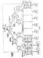
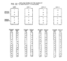
- FIG. 2 A simplified example is shown in the various representations of Fig. 2 of the manner in which the network 50 operates with the high speed random access memories in a tree using four different microprocessors, specifically an IFP 14 and three AMPs 18, 19 and 20.
- the diagram labeled simply Fig. 2 shows the state of the system prior to the beginning of signal transmission. In these separate views, the null or idle state requires a transmission designated O.
- the message packet "EDDV" from AMP 19 in Fig. 2A should be the first to be transmitted through the system.
- These messages are retained, as described in greater detail below, in the high speed random access memories (sometimes H.S. RAM) 26 in the microprocessors.
- all transmissions in the network 50 indicate the null or idle state D.
- the first byte of each of the message packets is launched into the network 50 concurrently, with all nodes 54 still returning the idle state indications and all transmissions above the first tier also being in the idle state.
- Node IN has received an "E" on both input ports and is transmitting this upstream to the next tier, indicating the undecided state downstream to both sending processors.
- node IN 2 has determined collision priority between the "E” from processor 19 and the "P” from microprocessor 20, in favor of the former, thus coupling port A to up-tree port C and providing the B eo ) signal back to microprocessor 20.
- the IN 2 node in effect locks the A input port to the C output port, so that the serial train from microprocessor 19 is transmitted on to the apex node IIN,.
- the message once broadcast to all microprocessors in this manner, may be used by any or all as required. This depends upon the mode of operation and the functions being performed, which include many variations.
- the destination selection information within the message packet itself provides criteria for local acceptance or rejection of the packet.
- interface logic in the receiving processor modules identifies whether the data is in range for their particular processor according to map information stored in the high speed RAM 26.
- a variety of selection criteria can be readily implemented by means of various settings of the map bits in the high speed RAM, including selection of a specific recipient processor, portion of the data base stored ("hashed"), logical process type ("class”), etc.
- the use of broadcasting with local access control is of particular benefit for a data base management system, inasmuch as minimal overhead software is needed to gain access to any part of the widely dispersed relational data base or to dispersed local copies of any of a number of globally known logical processes.
- the system is thus capable of specifically selecting a single destination or a class of resources as the destination for a message.
- TN incorporated in the messages provides this global transaction identity and reference, among other features.
- Many tasks may be worked on concurrently by the asynchronous local processor modules, and each task or subtask has its appropriate TN.
- An extended sort/merge operation can be undertaken on a large number of tasks that are asynchronously assigned and processed.
- TNs can be assigned and relinquished and merges can be started and stopped.
- Certain messages, such as continuations, can have priority over other transmissions.
- one query can determine the status of the global resource as to a given TN.
- a distributed update can also be accomplished in one communication. The present system enables all these functions to be performed without extending the software or materially increasing the overhead load.
- a coherent priority protocol that encompasses all message types, and various subtypes, embraces all the different messages that are applied to the network.
- responses, status and control messages are of a different form than the primary data messages they also use the contention/merge operation of the network and thus are prioritized during transfer.
- Response messages in the present system are positive acknowledgment (ACK), negative acknowledgment (NAK), or an indication that the processor does not have the resources to process the message meaningfully ("not applicable processor"-NAP).
- the NAK response may be any of several different types, indicating a locked, error or overrun condition. Because an originating processor or processors require such responses after termination of a message transmission, the responses have a higher priority level than primary data messages.
- the present system also employs SACK (status acknowledgment) messages that denote the readiness state of a local processor with respect to a particular task or transaction.
- SACK responses are locally updated and held accessible to the network. They provide, in conjunction with the merge operation of the network, a single query global status report for a given task or transaction. Because the status responses are in accord with the priority protocol, the lowest data content response automatically gains priority and establishes the least ready status as the global system state for a transaction number in one uninterruptible operation.
- the SACK indications also are used in conjunction with certain primary messages to implement various protocols, such as system initialization and lockout operations.
- the priority protocol definition for the various message types begins with the command code, using the initial 6 bits of the command word that starts each message and response, as shown in Fig. 11.
- An adequate range of distinctions as to message types, and subtypes, is available although more could be used.
- the SACK response differentiates seven different status levels (and provides a basis for prioritizing as well), as can be seen by reference to Fig. 11.
- For responses these first 6 bits are followed by the tag in the form of a 10 bit OPID (see Fig. 3). Both the TN and OPID can serve as further sorting criteria because of their differing data contents, within the tag.
- the interface section of every processor After each primary message has been transmitted through the network, the interface section of every processor generates a response message, even if it is only a NAP.
- the responses also content on the network, and the single or common winning response message is broadcast to all processors. Losing message packets are retried later, synchronously, after a minimal delay so that the network is substantially constantly in use. Where a number of processors provide an ACK response, the response are sorted by the OPID.
- Stop Merge, Status Request, Start Merge, and certain task assignment and relinquishment messages have the same format as data messages and are also referred to herein as primary messages.
- These control messages also include the TN and have their places in the priority protocol, as is later discussed relative to Figs. 10 and 11.
- the term "global semaphore buffer system" has been adopted to connote the fact that the high speed random access memory 26 and control logic 28 shown in Fig. 1 also play a significant role in both multiprocessor mode selection and bidirectional communication of status and control indications.
- the global semaphore buffer system provides duality of access, in that both the high speed network structure 50 and the slower speed microprocessors can reference a message, response, control or status indication in the memory 26 without delay or requiring direct communication with each other.
- the control logic 28 time multiplexes the memory 26 to network 50 and to the microprocessor in interleaved word cycles, creating in effect different ports having common access to the memory 26.
- the global resource or network 50 and microprocessors can use the transaction number as an address locater to a portion of the memory 26 devoted to transaction status.
- the status of a subtask relating to a given transaction covering all useful states is updated in the memory 26 under control of the microprocessor and locked by the control logic 28 at the buffer system.
- One of seven different readiness states is used, the entries conveniently being derived from a different dedicated portion of the memory 26.
- the status of the processors is communicated (the "semaphore" is read) and prioritized in the network with the least complete readiness state taking priority. This arrangement provides an immediate hardware response from all processors to a query.
- any communicating processor module can assign an available transaction number for use with the messages and in each global semaphore buffer system.
- all active processors connected to the network 50 can be working asynchronously on messages pertaining to different transaction numbers.
- the START MERGE message tests the global semaphore represented by a particular transaction number, and if the global state is ready (SEND READY or RECEIVE READY), the present transaction number (PTN) is set to the TN conveyed in the START MERGE message. (If the global state is not ready, the PTN reverts to a value of TNO).
- a STOP MERGE message also resets the present transaction number to 0. TNO is thus utilized as the "default" transaction number used for single processor to single processor (point-to-point) messages. In another sense, it identifies the "non-merge" mode of operation.
- the global intercommunication system uses the message organization shown in Figs. 3A, 3B, 3C and 11, and the high speed random access memory 26 organization shown in Figs. 8 and 10. More detailed examinations are made below in conjunction with Figs. 5, 7, 9 and 13.
- command codes for the responses range from 00 to OF (hexadecimal) and that those for primary messages range from 10 (hexadecimal) to some higher value.
- responses take priority over primary messages, lowest value first, in the sequence shown in Fig. 11.
- One dedicated section of storage in the high speed RAM memory 26" (Fig. 8), (designated “transaction numbers”) is used for storage of the word formats (the seven readiness states, an Assign TN and an Unassigned TN state) of Fig. 12.
- Other dedicated portions of the memory 26" include a circular buffer for input (receive messages) and an output message space.
- Another separate section of the memory 26" is used as a message complete vector section, in which pointers can be placed to completed output messages so that output message space can be used efficiently.
- the active logic nodes 54 of Fig. 1 are alike, in both of the redundant networks, except that the recirculation node 54a at the apex of each network has no upstream port, but merely a signal recirculation path that returns to the downstream direction.
- each node 54 may be broadly divided into functional groupings, one of which pertains to message and collision signal transmissions and the other of which pertains to generation and retransmission of the common clock signal. Clock signals are synchronized such that there is zero skew between them at the different nodes. These two functional groupings are not separate, inasmuch as the zero skew clock circuits form important parts of the signal transmission system.
- Both a word clock (two serial bytes) and a byte clock are utilized. Note should be taken of the fact that external control of the active logic nodes 54 is not required or utilized, whether to establish or reset the node's state or to set up different modes of operation. Furthermore, the identity between the nodes 54 enables them to be made in quantity using modern IC techniques, substantially reducing cost while improving reliability.
- the A, B and C "ports" previously referred to each have ten input data lines and ten output data lines. Taking the A port as an example, the input lines are designated A1 and the output A0.
- the single "collision" line is used at each port (e.g. A col for the A port), along with upstream and downstream clock lines.
- the data lines from the A and B ports are applied to a multiplexer 60 which switches the priority word of two competing words, or the common word (if both words are alike) to an up register 62 coupled to the upstream port (C) as the CO data signals.
- the downstream data received at the C port from a higher tier node is shifted into and out of a down register 64, appearing as output at both of the A and B ports.
- Competing bytes concurrently applied at the A and B ports are supplied to first and second parity detectors 66, 67 and also to a comparator 70 which determines priority on the basis of the eight data bits and one control bit, with lowest data content having priority.
- the "idle" or no message signal in this protocol is an unbroken sequence of 1's. Parity errors can occur due to typical causes, such as the presence of excessive noise or some other factor affecting signal transmission or circuit operation. In the present system, however, an important additional use is made of parity error indications.
- Each transition of a microprocessor to an inoperative state is marked by all output lines, including the parity line, going high (or 1 valued), thus establishing an odd parity error. This indication is transferred through the network once upon the presence of an error, as a marker which enables the system to identify a change in global resources and initiate procedures to determine the nature of the change.
- the pair of parity detectors 66, 67 and the comparator 70 feed control circuits 72 that include priority message switching circuits 74, responsive to the comparator 70 for locking the multiplexer 60 in one state or the other if priority is determined, and for generating and propagating the downstream collision signals.
- Transitional parity error propagation circuits 76 are so called because they force the one-time all l's parity error state along the network.
- Reset circuits 78 for returning the node to its initial state include an end of message (EOM) detector 80.
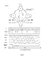
- the functions described above and hereinafter may be accomplished at each active logic node by the use of a microprocessor chip, but they may even more readily be implemented in accordance with the state diagram of Fig. 5 and the logic equations set out below.
- the state SO represents the idle state, and also the state in which competing messages are equal, so that no decision is made to favor one port against another.
- the S1 and S2 states are the states favoring the A port and B port respectively.
- the A port is favored (S1 state is established) if the data content of BI is greater than AI and there is no parity error on AI or if there is a parity error on BI (these conditions being designated AIPE and BIPE respectively and represented by flip-flop states).
- the reset circuits 78 include the EOM detector 80, used to reset the node from S3 to SO (Fig. 5).
- a first reset mode uses the end of message (EOM) field that concludes the data field in a primary message, as shown in Fig. 6.
- EOM end of message
- a group of flip flops and gates are used to establish the logic:
- control bit sequence pairs establish certain fields and transitions between them. For example, a transition from the all 1's used during idle to a 0, bit sequence defines the start of a field. The same 0, 1 sequence is used to identify the start of the data field. Successive 1, 0 control bit strings denote the internal field or subfield, and the end of message (EOM) is identified by the 0, 0 control bit pair. The condition in which the string of 1, 0 pairs is followed by the 0, 0 pair is unique and readily identified.
- the URINC, URC and URCDLY signals are ANDed together, with each having a 1 byte clock delay from the other. The result is a waveform that is high until the start of the message packet, and at which point it goes low and stays low through the data.
- a higher node tier that is reset goes to COL IN indicating that the collision state has been removed.
- This logic state initiates a return from S3 back to the base state, S0.
- the COL IN state will propagate down the tiers of the network as the end of the message "runs out".
- the nodes are thus self-resetting no matter how long or short the message. Also note that no matter the state in which the network starts out, all nodes will be reset to the SO state by the idle signals.
- Collision signals are returned to the processor modules, which store the collision state information and revert to the transmission of the idle sequence as the winning processor continues to transmit.
- a processor may begin a new transmission as soon as it detects the transition from COL IN to COL IN .
- a. processor may begin a new transmission after receiving idles for 2N byte times, where N is the number of tiers in the network, as this also indicates that the network is clear of any prior transmissions. This latter method of enabling new transmissions permits a processor entering a network for the first time to get into message synchronism with the network under conditions of light traffic, so that it need not wait for a poll from another processor in order to start interchange with other processors on the network.
- Parity error states have been noted in the state diagram of Fig. 5 and are established pursuant to the following logic:
- the transitional parity error propagation circuits 76 comprise an AIPE, or A input parity error flip flop and a delay flip flop (AIPEDLY). The latter is set 1 byte clock later in accordance with the AIPE setting. For A inputs, the PESIG value thus goes high for 1 byte clock when the AIPE flip flop is set by a parity error, so that the PESIG signal is propagated once, at the first indication of the parity error. The same condition arises when all of the data bits, control and parity bit are 1 values, which occurs at the previously noted transition in the state of the global resources. A !
- Parity errors arising because of noise effects or other variables will typically not affect processor operation because of the redundant networks.
- indicator lights (not shown) are utilized to indicate the occurrence of parity error.
- the once-propagated parity error denoting change of status initiates routines for assessing the significance of the change.
- the clocking system used in the node 54 provides a unique means for maintaining zero skew between the clocks at all the node elements, despite the number of tiers used in the network.
- the clock circuits 86 include first and second EXCLUSIVE OR gates 88, 89 respectively, the outputs of which designated A and B, respectively, are subtractively combined (in the B-A sense) by a summing circuit 92, the output of which is passed through a low pass filter 94 to control the phase of the output from a phase locked loop or oscillator 96.
- the inputs to the first gate 88 are the output of the PLO 96 and a downstream clock passed from the next higher tier node element through an isolating driver 97.
- This line is designated as the word clock, and is derived from the next higher tier after a certain known delay, ⁇ , the same signal being returned through another isolating driver 98 to the node at the next higher tier.
- the inputs to the second gate 89 comprise the word clock and a clock feedback from the next lower tier, which also receives a signal from the PLO 96.
- the word clock line feeds the two inputs of a third gate 100, both directly and through a ⁇ c delay line 101, to derive a byte clock signal at twice the frequency of the word clock and in timed relation to it.
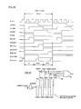
- the functioning of the clock circuits 86 may be better understood by reference to the timing diagram of Fig. 7.
- the clock out signal is the output of PLO 96.
- the transmission line delay T between nodes is kept substantially constant, but can be long. Using the presently disclosed technique the length could be as long as 28 feet, with the network and node byte clock rates (nominally 120 ns.) used in a practical system.
- the word clock derived from the next higher tier, as shown by the next lower waveform, is a similar waveform but delayed by T .
- the word clock constitutes the basic timing reference throughout all the nodes, and this is made possible because the leading edge of each clock out signal is controllable within the circuit and can be made to lead the word clock so that all nodes can be held in synchronism. Referring to the waveforms A and B, it can be seen that the first gate 88 generates a pulse A which terminates with the leading edge of the word clock, while the second gate 89 generates a pulse B whose leading edge is coincident with the word clock.
- the trailing edge of the B pulse is defined by the initiation of the feedback pulse from the next lower tier mode, which is delayed by T , so that the B pulse is of fixed duration.
- the clock circuits 86 function to keep the pulse A of the same duration as pulse B, because the summed signal, B-A, tends toward a null, as the PLO 96 is advanced in phase so as to establish synchronism.
- the leading edge of the A signal which may lead or lag the desired position as shown by dotted lines, is adjusted to precede the leading edge of the word clock by the interval ⁇ .
- the leading edge of the clock out signal is in this desired nominal position at all the nodes, there is zero skew between the word clocks. For this reason the processors coupled to the network are freed from any constraints as to the total length of the path between one processor and another, because additive delays and differential propagation times are eliminated.
- the word clock signal is replicated at a delay Te by the delay line 101, which also feeds the gate 100.
- a byte clock pulse is produced having a duration T .. This occurs twice each word clock interval and in synchronism with the word clock throughout all the nodes. It is implicit in the prior description that the delay introduced by the transmission lines between nodes are nearly identical in both directions between tiers so that in effect all word clocks and byte clocks within the system are held in stable phase relationship.
- the locally generated byte clocks therefore provide clocking at each node for the individual bytes in the 2 byte words of the messages.
- the active logic nodes are of potential benefit wherever a competition between concurrent message packets is to be resolved on the basis of data content.
- Most known systems as exemplified by patent No. 4,251,879 issued February 17, 1981 on a "Speed Independent Arbiter Switch for Digital Communication Networks" are directed toward determining the first signal received in time, and utilize external processing or control circuits.
- processors in the overall system diagram of Fig. 1 are identified as examples of interface processors (lFPs) 14 and 16 and access module processors (AMPs) 18 to 23 respectively, and are broadly subdivided into principal elements.
- lFPs interface processors
- AMPs access module processors
- a more specific example of the organization of the processor modules shows the correspondence to the broad functional subdivisions of Fig. 1 but also reveals a substantial number of further subdivisions.
- processor module refers to the entire assembly shown in Fig. 8, which with the optional features that are noted can serve either as an IFP or an AMP.
- microprocessor system refers to a system 103 that incorporates a microprocessor 105 such as a 16 bit microprocessor of the Intel 8086 type.
- the address and data busses of the microprocessor 105 are coupled within the microprocessor system 103 to conventional peripheral systems, such as the main RAM 107, and a peripheral controller 109.
- the peripheral controller 109 exemplifies what may be used when the processor module is an AMP and the peripheral unit is a disk drive 111. As shown in the dotted line rectangle, however, this controller or interface may alternatively be a channel interface if the processor module is to serve as an IFP. In this instance the channel interface would communicate with the channel or bus of a host system. Inasmuch as conventional controllers and interfaces may be used in the microprocessor system 103, they need not be further described.
- the peripheral controller 109 and the channel interface depicted as an option in the microprocessor system 103 correspond to the IFP interface and disk controller in Fig. 1.
- the high speed RAM 26 of Fig. 1 actually comprises first and second H.S. RAMs 26', 26" respectively, each of which through time multiplexing is effectively a three-port device coupled to the microprocessor bus system at one of its ports (designated C).
- Each of the H.S. RAMs 26', 26" cooperates respectively with a first or second network interface 120,120', providing communication with the first and second networks 50a and 50b (not shown in Fig. 8) respectively at an input (receive) port A and output (send) port B.
- the network interfaces 120, 120' are further shown and described in conjunction with Fig. 13, but can be generally subdivided into four principal parts:
- An output register array and control 124 coupling the output lines of the second network 50b to the interface data and address busses and to the B port of the second H.S. RAM 26".
- a microprocessor bus interface and control 126 coupled to the interface address and data busses and to the A and B ports of the H.S. RAM 26".
- a clock generator 128 that receives the word clock from the network and generates synchronized, properly phased clocks for controlling the interface 120'.
- the second network interface 120' and H.S. RAM 26" cooperate with the microprocessor system 103 in coordinating data transfers between the high speed network and the relatively slower speed microprocessor and also provide queuing of messages between these different systems.
- the microprocessor bus interface and control 126 may be referred to as performing read/write (R/W) functions with the microprocessor system which (at least with the Intel 8086) has the capability of writing directly into and receiving data from the H.S. RAM 26".
- the IFP and AMP systems are functionally alike, there can be a substantial disparity in the sizes of the incoming message storage and outgoing message storage in the H.S. RAM 26", as between the IFP and the AMP.
- the IFP has a large incoming message space in the H.S. RAM 26", in order to receive new messages from the high speed network so that the needs of the host computer may be serviced by constant usage of the network.
- the AMP the reverse is true, because more storage space should be available to send processed message packets to the high speed network.
- the H.S. RAM 26" functions with the main RAM 107 in the microprocessor system 103, which has the message buffer sections for each network.
- Fig. 9 The allocation of system address space in the main RAM 107 for the microprocessor system 103 is shown in Fig. 9, to which reference should briefly be made. It is conventional in having addresses devoted to system random access functions, an expansion space for use in the event the random access capacity is increased, and I/O address space and an address space reserved for ROM and PROM (including EPROM) functions. In addition, portions of the system address space are reserved for message packets from and to the first and second high speed RAMs 26', 26" respectively. This provides greater flexibility in the system operation, inasmuch as even though the microprocessor 105 can address the H.S. RAMs 26", the main RAMs 107 assure greater freedom from software and hardware interdependence.
- the bidirectionally accessible H.S. RAMs 26" are organized in such fashion that they perform central functions in multiprocessor mode control, distributed updating and the management of message packet flow.
- the H.S. RAM 26" is divided into a number of different internal sectors.
- the relative disposition of the different sectors shown in Fig. 8 is used throughout the different processor modules in the system, and the specific addresses that designate the limits of the sectors refer to those used in an actual system. It will be appreciated that the sizes of these sectors of memory and their relative disposition are widely variable dependent on the specific system context. Sixteen bit memory words are employed in this example.
- the selection map and response directory are dedicated lookup tables of the type that may be written in once during initialization, while the transaction number section provides a dynamically revisable lookup table.
- the selection map section of memory starts with location 0 but is based upon the use of four different maps used in interrelated fashion within the memory section.
- the destination selection word (DSW) that is contained within the message packet is used cooperatively with the dedicated selection maps in the H.S. RAM 26".
- the destination selection word comprising 16 total bits, has a map address in 12 bit positions, and map selection data in the four other bits.
- Each of the first 1024 16 bit memory words of the H.S. RAM contains four map address values.
- the address value specified by the DSW provides, with a single memory access to the H.S. RAM, map bits for all four maps, while the map selection bits in the DSW determine which map is to be used.
- Fig. 15 shows the conceptual organization of the map section as if each map had physically separate 4096-by-1-bit RAM. As a matter of implementation convenience all map data is stored in a single portion of the H.S. RAM, as shown by Fig. 8.
- the DSW Management Section 190 (Fig. 13) controls multiplexing of four bits from each of the four maps of Fig. 15 from one 16-bit word of H.S. RAM.
- Fig. 13 controls multiplexing of four bits from each of the four maps of Fig. 15 from one 16-bit word of H.S. RAM.
- the maps can be initialized by the processor by the same means as used to access other parts of the H.S. RAM.
- the selection map locations are correspondingly divided into a hash selection portion, a class selection portion and a destination processor identification (DPID) selection portion.
- the DPID specifies whether the processor 105 is the specific one for which the message packet is intended, whereas the class selection portion specifies whether or not the processor is one of the number of processors in a particular process class that is to receive the message packet.
- the hash values are stored in accordance with the manner in which the data base is distributed throughout the relational data base system, following a predetermined algorithm for the particular relations and method of scatter storage that is employed. The hash value in this instance can designate the processor either as having primary or backup responsibility for the data.
- the selection maps provide a technique for directly addressing the H.S. RAM 26" so as to determine processor destination. This function complements the broadcasting of prioritized messages to all network interfaces 120' and enables local accessing without interruption of microprocessor 105 status.
- H.S. RAM 26" serves as a pivotal means for checking and controlling globally distributed activities.
- Transaction numbers are assigned to various ones of the processes that are sent on and received from the network 50b, as discussed above and shown in Fig. 3.
- TNs within messages are retained as global transaction identities as each microprocessor system 103 independently performs the subtasks accepted by it.
- the block within the H.S. RAM 26" that is dedicated to a number of available transaction number addresses contains status entries that are locally controlled and updated by the microprocessor system 103 as these subtasks are performed.
- the TN is used in a number of different ways, both locally and globally, in performing intercommunication functions.
- the transaction number is used to identify subtasks, to call forth data, to provide commands, to control message flow and to characterize the dynamics of a gobal process. Transaction numbers may be assigned, relinquished and changed in the course of global communication.
- the most complex, but perhaps the most dramatic, aspect of the TN is the capability it affords, with the sort network, for distributed updating of the status of local processors as to a given control process.
- Each control process i.e., task or multiprocessor activity
- Readiness state values are held in the transaction number section of H.S. RAM 26" and are locally modified under control of the microprocessor system 103.
- the microprocessor 103 can initialize the appropriate entry (e.g. SACK/Busy) in the response directory (address 050D (hex)) of Fig. 10, and enter the SACK/Busy status by transferring the exact image thus reproduced to the H.S. RAM 26".
- An entry at a TN address is accessible to the network 50b via the interface 120', at the A and B ports of the H.S. RAM 26". Queries are made using a Status Request message containing the status request command code (see Fig. 11) and TN.
- the interface 120' uses the content of the designated TN to reference the response directory which contains a properly formatted response message.
- a global status query as to a given TN when received at the second network interface 120' elicits a direct response that is solely hardware controlled. No prefatory communication is needed, and the microprocessor system 103 is not interrupted or affected. However, the microprocessor 103 can assure against interruption when setting the status by transmitting a LOCK indication to the interface 120', which communicates the Lock word derived from 0501 (hex) until removed at a later time.
- the word format of the readiness states is shown by the seven states from “busy” to "initial” in Fig. 12, which depict the useful variants employed in a practical system. More or fewer status variants may be used, but these seven states provide versatile and comprehensive control. It is the responsibility of the microprocessor system continually to update status levels for different TNs in the H.S. RAM 26" to reflect availability for, or progress toward the completion of a subtask. Such updates are made simply by writing into the TN address in the H.S. RAM 26", using the formats shown in Fig. 12.
- each status response is accompanied by an initiating status acknowledgment command code (SACK), from 05 to 0D (hexadecimal).
- SACK responses sent to the network are essentially the command codes of Fig. 10, the numeric portions of the word formats of Fig. 12, and an originating processor ID (OPID), as seen in Fig. 11.
- the SACK responses thus define a consecutive priority subgrouping within the overall coherent priority scheme shown in Fig. 11.
- the OPID is significant in the priority scheme, because if a number of processors are working on a TN but are "Busy", the highest priority message that is i broadcast is determined by the OPID. Transfers and system coordination can be based on this data.
- the SACK message priority schedule, the simultaneous responses from a number of microprocessor systems 103, and the dynamic prioritizing in the network 50b, enable the status of global resource as to a given task to be determined in a vastly improved manner in comparison to prior art systems.
- the response given is unambiguous, cannot represent an invalid state and requires no software or local processor time. Thus Deadlock cannot arise due to repeated requests interfering with task performance, for example. Numerous multiprocessor options can be used at the different status levels. It is unique that the local processors can continue to operate independently and that a single query derives a global, prioritized, response.
- Fig. 12 Some specific discussion of the successive states depicted in Fig. 12 may be useful.
- the "busy” and “waiting” states cannote successively more complete phases as to the assigned subtask, the latter identifying a condition in which a further communication or event is required.
- These states exemplify the "elevation" of the status of the TN until it reaches a level at which a message packet corresponding to the TN can be sent or received.
- the microprocessor system 103 When a message packet is to be sent or received, however, a different feature of the TN comes into play, namely its capability for message control.
- the status indication becomes "send ready”.
- the microprocessor system 103 not only updates status but it also enters a "next message vector" value in the H.S. RAM 26", using the word format of Fig. 12. This entry defines the location at which the corresponding output message may be fetched from H.S. RAM 26". This vector is used internally in the network interface 120' in chaining together output messages pertaining to a specified TN.
- a related function is performed during the "receive ready" state, in which the TN storage location retains an input message count from the microprocessor system 103 as to the number of messages that may be received pertaining to a given TN. This count can be decremented until reduced to zero as successive input messages are transferred. At zero, no more messages can be received and an overrun condition can be indicated. This enables the TN to be used in pacing transfer between the network 50b and the microprocessor system 103.
- the TN is retained in the send and receive messages during processing, as a constant and uniform reference throughout the system.
- the TNO or default state also provides a local command to identify the fact that a message is to be used in a non-merge mode.
- TNO and TN>0 values establishes one of the command functions for which the TN is used.
- the merge/non-merge characterization thus inherent in each message packet, provides a valuable systems approach to prioritizing and sorting messages.
- the "Assigned”, "Unassigned”, “Non-Participant” and “Initial” status are used to fulfill global intercommunication and control functions.
- the "Unassigned” state is one in which the processor has previously relinquished a TN, so that it must receive a new primary message reactivating the TN. If the processor indicates "Unassigned" when it should be "Assigned”, this establishes that the TN was not properly entered and that corrective action should be taken.
- the dedicated directory or reference section of the H.S. RAM 26 also includes other types of prioritized messages for use in generation of responses by hardware.
- NA not assigned entries are held available for future use.
- Three different types of NAK responses (Overrun; TN Error; Locked) are of lowest data content and at highest priority levels because they identify error , conditions.
- the SACK responses are followed, in order of decreasing priority, by the ACK response and the NAP (not applicable processor) response.
- two response command codes are not assigned (NA) and are available for future use.
- This directory can be initialized by software and is used by hardware to quickly and flexibly generate any of the range of response message texts.
- a separate portion of this directory is used to store TOP, GET, PUT, and BOTTOM addresses or pointers related to the functioning of circular buffers for input messages and completed output message pointers. These pointers function in conjunction with the dedicated sectors of H.S. RAM 26" devoted to input message management and output message management respectively.
- a circular buffer scheme is used, with "TOP" stored in the directory section of the H.S. RAM 26", being a variable address defining the upper position for incoming messages.
- the PUT address also stored in the directory section, defines where the circuits are to store the next message that is received.
- the GET address is provided and kept updated by software to enable the hardware to recognize the location at which the software is emptying the buffer.
- the incoming message buffer is managed by setting PUT at the bottom of the buffer and starting with the GET address equal to TOP.
- the rule of operation assured by software is that GET is not set equal to PUT, which would create an ambiguous condition.
- the message length value in the message itself establishes the beginning point of the next message and the PUT address stored in the directory is then changed to indicate where the next succeeding message is to be received in the buffer. Incoming messages can thus be fetched by the microprocessor system 103 as its capabilities permit.
- Data in the output message space within the H.S. RAM 26" is utilized in conjunction with the output message complete vectors held in a separate circular buffer and the next message vector in the H.S. RAM 26".
- Messages can be assembled and stored in arbitrary locations, and related messages can be chained together for transmission on the network.
- TOP, BOTTOM, PUT and GET addresses are entered and updated as previously described to maintain active present references to locations within the output message complete buffer.
- the message complete vectors constitute addresses which reference messages in the output message space that have been successfully transmitted as indicated by a response received.
- the system enables the microprocessor system 103 to enter output messages readily, but to handle complex linkage vector sequences in orderly fashion so that output message space is efficiently used and message chains can be transmitted.
- the stop merge (also the base or non-merge control) message is of lowest data content and highest priority. This message constitutes a control communication that terminates merge mode within the network and at the processor modules.
- a substantial number of different types of primary data messages can be used in ascending priority, and can be categorized in priority order based upon application and system requirements. As mentioned, continuation messages can have higher priority so as to maintain continuity with the preceding message packet to which they relate.
- the last grouping of four primary messages in Fig. 11 comprise, in descending order of priority, the status request message, which is the only type of status message needed to obtain the status response, control messages calling for "relinquish TN" and "assign TN", and, of lower priority, a "start merge" control message.
- a processor module operates on a present transaction number (PTN hereafter), whether this is externally commanded from the network or generated internally in the course of successive operations.
- PTN present transaction number
- the processor modules utilize the global reference or transaction identity defined by the TN.
- Starting, stopping and restarting of merge operations utilizes only simple message changes.
- subtasks do not require messages to be merged, or message packets are generated that have no specific relationship to other messages, they are queued to an output against TNO and are transmitted when the base or default condition defined by Present Transaction Number (being 0), holds true.
- TNO condition enables messages to be queued for transmission whenever a merge mode is not utilized.
- Fig. 13 depicts in further detail one example of interface circuits useful in systems in accordance with the invention. This section of the description includes a number of detailed features that are not necessary to an understanding of the invention but are embedded in a practical system example and are therefore included to place the examples more firmly in context. Specific gating arrangements and details not the subject matter of the invention and involving well known expedients for which many alternatives are available have been omitted or abbreviated.
- Fig. 13 is an elaboration of the second network interface 120' and the H.S. RAM 26" from Fig. 8. The interfaces 120 for both networks function in like fashion and thus description of one will suffice.
- Fig. 13 inputs from the particular active logic network 50 associated with the interface are applied at network message management circuits 140 via a multiplexer 142 and known parity check circuit 144.
- the multiplexer 142 is also coupled to the microprocessor system data bus, enabling access to the message management circuits 140 via the bus. This feature permits the microprocessor system to operate the interface in a step-by-step test mode, transferring data as if the interface were on line to the network.
- Inputs from the networks are applied to a receive network data register 146, both directly in a first section and through a receive byte buffer 148 which thereafter enters the byte into a different section of the receive network data register 146. Consequently, both bytes of each word received are entered into and held available at the receive network data register 146.
- Output messages for transmission are entered into a send network data register 150, while a parity bit is added in a conventional parity generator 132. Messages are sent to the associated network from the network message management unit 140, or (where the test mode is to be used) to the microprocessor system data bus.
- the send message format in the random access memory 168 comprises identifying data as well as message data. As seen in Fig. 21A, command, tag, key and DSW can all be incorporated along with primary data that is to be transmitted.
- Fig. 13 The organization shown in Fig. 13 is essentially the same as that shown in Fig. 8, which illustrates the interface data bus and address bus as separately coupled to input ports A and B at the H.S. RAM 26', while the address and data busses of the microprocessor system 103 are illustrated as coupled to a separate C port. In actuality, as seen in Fig. 13, this separate bidirectional access is achieved by time division multiplexing of input and output address functions within the interface and at the H.S. RAM 26".
- the microprocessor data and address busses are coupled to the interface busses via gates 145,149 respectively so that the microprocessor can operate asynchronously on its own internal clock.
- the timing system used is based upon clock pulses, phase control waveforms and phase subdivision waveforms generated by interface clock circuits 156 (Fig. 13) and having the timing relationships shown in Fig. 14, to which reference is also made.
- the interface clock circuits 156 receive the network word clock from the nearest node and a phase locked clock source 157 includes means for maintaining zero time skew as previously described in conjunction with Fig. 4.
- the nominal network word clock rate of 240 ns. in the network is subdivided in time in the interface clock circuits 156 because a frequency multiplier (not shown in detail) held in phase locked relationship provides a faster clock defining reference period of 40 ns. duration (shown in Fig. 14 as PLCLK).
- the basic word period is defined by the opposite-going half cycles of a cyclic signal designated CLKSRA having a total 240 ns. duration.
- CLKSRA cyclic signal having a total 240 ns. duration.
- Two other signals of like frequency and duration are generated from PLCLK by frequency dividers 158 at times delayed by one and two cycles of PLCLK respectively from CLKSRA, and these are designated CLKSRB and CLKSRC respectively.
- control logic 159 develops timing waveforms, designated 10 GATE, RECV GATE and SEND GATE, denoting successive equal thirds of the word period. These intervals are appropriately referred to as 10, receive and send phases.
- the phases defined by the gate signals are each further subdivided into two equal half intervals by 10 CLK, RECV CLK and SEND CLK signals which define the last half of each of the phases.
- Byte clocking functions are governed by BYTE CTRL and BYTE CLK signals.
- the 10, RECV and SEND phases provide the basis for time division multiplexed operation of the random access memory 168 and the microprocessor system busses.
- the interface can receive or send no more than one word per word period from or to the high speed network, and receiving and sending are obviously never concurrent. Transfer rates to and from the microprocessor system are substantially lower, but even if equal the capacity of the interface circuits would not be taxed.
- the interface system arrangement hinges in large part on direct access to the random access memory 168, and substantial obviates the need for internal processing or software. Thus as the system cycles through the successive phases in each word period, words are successively advanced in non-conflicting progressions along their predetermined signal paths for the different functions taking place. For example, sending a message to the bus may be interleaved with reception of a message from the microprocessor, each being interchanged using a different portion of the memory 168.
- Intercommunication between the data bus for the microprocessor system and the network interface is effected in 10 (which may also be referred to as Read/Write) mangement circuits 160.
- a write gate 162 for words from the microprocessor system, and a system read register 164, for transferring words to the microprocessor system provide the coupling between the microprocessor's bus and the bus interface to the network interface.
- a memory address register 165 and parity generator and check circuits 166 are also incorporated in the network interface subsystem.
- the high speed storage comprises a 4K wordx17 bit random access memory 168, the internal subdivision of which and the use of dedicated memory portions within which have previously been described.
- the size of the random access memory can readily be reduced or expanded to meet the needs of a particular application.
- Receive message buffer management circuits 170 are coupled to the data bus of the microprocessor and in turn are coupled to the address bus for the memory 168.
- the term "received messages” refers both to the incoming messages from the network for entry into the circular buffer at a location referred to as PUT and to the subsequent transfer of that message to the microprocessor system when a GET value specifies where the system is to sequence in extracting a received message for transfer to the microprocessor system.
- Address values for accessing the random access memory 168 are entered into a GET register 172, a TOP register 174, a PUT counter 175 and a BOTTOM register 176 respectively.
- the PUT counter 175 is updated by incrementing from an initial position defined by the BOTTOM register 176.
- the TOP register 174 provides an opposite limit reference. Both TOP and BOTTOM may be manipulated by software control to modify both the size of the receive buffer and the absolute location with H.S. RAM. When the contents of the PUT register equal to contents of the TOP register, the PUT register is reset to the contents of the BOTTOM register, thus effecting the circular nature of usage of the buffer.
- the GET, TOP and BOTTOM registers and the PUT counter are shared in managing both the incoming message and output message complete circular buffers.
- Entries are made in the GET register 172 under software control, because the length of the then active message in the buffer determines the next address.
- Comparison circuits 178, 179 coupled to the outputs of the GET register 172, the PUT counter 175 and the TOP register 174 are used in detecting and indicating overrun conditions. An overrun exists when the GET and PUT settings are set equal or when GET is attempted to be set greater than TOP. In either instance an overrun status indication is to be sent until the condition can be corrected.
- the concatenated manner in which the "receive message" circular buffer is arranged and operated is particularly useful in the present system. Hardware management of PUT and dynamic management of GET can be employed with cross-checks being available to avoid conflict. However, other buffer systems may be employed, although perhaps at some added expense in circuitry and software.
- the receive message format in memory 168 also, referring now to Fig. 21 B, contains identifying data in the form of map results, data length and key length, derived as described hereafter.
- a DSW management section 190 within the interface includes a destination selection word register 192 into which the destination selection word is entered for transfer to the address bus.
- the output on the data bus, from the memory returns data from which the DSW management section 190 may also determine that the message packet is appropriate for the processor.
- the Destination Selection word comprises 2 bits of map nybl address, 10 bits of map word address, and 4 bits for map selection.
- the "nybl" address is used to delineate a subsection of a word from memory 168.
- the 4 map selection bits are applied to a map result comparator 194, which receives relevant map data from the memory 168 via a multiplexer 196.
- the multiplexer 196 receives 16 bits, representing 4 different map data nybls stored at the address defined by the 10 map word address bits in the DSW.
- the memory 168 is specifically organized in comparable fashion in the dedicated map section to facilitate this comparison.
- the appropriate one of the four map nybls is selected by the 2 remaining bits in the DSW, applied to control the multiplexer 196.
- a comparison is made, and the resulting map code is entered in the map result register 197 and inserted in the incoming message entered in the memory 168. If the comparison shows that a "one" bit is not present in any of the selected maps, a "reject" is generated to indicate that the processor module is not intended to receive the message packet.
- Fig. 15 there is shown in general form an advantageous way to subdivide the memory 168 in the dedicated destination selection portion and to make the map result comparison.
- Each map is organized as 4096 wordsx 1 bit, and further subdivided (see Fig. 8) into specific processor ID, class ID and hashing sectors.
- 12 address bits (10 address and 2 nybls) the common map address is selected and a 1 bit output is derived from each map.
- the multiplexer and nybls of Fig. 13 are not shown for simplicity in Fig. 15).
- the four parallel bit outputs can be compared to the 4 map selection bits in a group of four AND gates 198, so that if one or more compare, the output of an OR gate 199 goes true.
- the map result can be entered in the map result register 197 of Fig. 13 and the message can be accepted in the memory 168. Alternatively, the message is rejected and a NAK is transmitted.
- the command word management section 200 includes a command register 202 that receives the command word.
- the TN field of the command word has access to the address bus so that the referenced receive TN may be examined to determine the proper response message (see Fig. 18).
- a data path exists from the TN field to the PTNR 206 in order that the PTN value may be changed in conjunction with a Start Merge command.
- the incoming messages entered into the memory 168 also include, as discussed relative to Fig. 21, for address vector purposes, the value of the length of the data field and the key field, if these fields are used. These values are derived by a receive data length counter 210 and a receive key length counter 211, each of which counts the sequence of words in the appropriate field as the fields are presented by the input source.
- a send message management section 220 is also used to encompass the functions of accepting processed packets for memory 168 and transferring them to the network at a later time.
- This section 220 comprises a send transaction vector counter 222, a send data length counter 224 and a send key length counter 226 coupled bidirectionally to the data bus.
- the send transaction vector counter 222 is coupled to the address bus, while the send data length counter 224 is coupled to an address generator 228 which is in turn coupled to the data bus.
- the output buffer section and the circular buffer comprising the output message complete vector section of Fig. 8 are both used in sending messages. In this instance, however, message packets are entered serially, but then fetched in a sequence defined by the vectors.
- phase controls respond to control bits which generate command, DSW, data and other signals denoting the individual fields within the messages.
- Send state controls 250, receive state controls 260 and R/W state controls 270 receive the clock pulses, identify the fields within the data and control sequencing of data flow during the send, receive and processor clock.
- Control of the interface is then effected by three finite state machines (FSMs) one each for the send, receive and processor (R/W) phases.
- FSMs finite state machines
- the FSMs are implemented in a conventional manner, using programmable logic arrays (PLAs), a state register and action ROMs. Each FSM is advanced to its next state once per network clock cycle. Because of the number of control signals to be generated, the outputs of the PLAs are further encoded by action ROMs.
- the state diagrams thus are essentially self explanatory, when taken in conjunction with Fig. 13 and the specification.
- the state diagrams detail the sequences and conditional statements involved in complex message management and inter-processor communication.
- Fig. 17 the states labeled "Generate Response” and "Decode Response” and the conditional statements indicated by dashed line rectangles are in accordance with the designated responses and actions set out in the matrix diagram of Fig. 18.
- Fig. 18 depicts both the responses generated and the actions undertaken for any given combination of primary message and readiness state pertaining to a given TN. Obviously, normal system operation involves some message rejection but very few Error Conditions.
- Primary data message reception and transmission-Fig. 16 is a simplified state diagram of the states involved in the ultimate acceptance of a primary message. Reception of the message, at buffers and in storage, does not effectuate acceptance until these logical states have been satisfied. Although depicted as a serial train of events, determinations are essentially made in parallel or concurrently because conditions are mutually exclusive or circuitry bypasses intermediate stages in arriving at a certain operating level.
- a message on the network of Fig. 1 is passed through the receive network data register 146 of Fig. 13 until the EOM state is identified, at which point it is known that the message is complete. If a LOCK condition exists, the system references the response directory in the H.S. RAM 26" of Fig. 8, sending the NAK/LOCK reject message.
- the system is then ready to check for TN status by making reference to the directory of the TN's as shown in Fig. 8, specifically to determine whether the local status is "receive ready". It is assumed that the TN was previously assigned by a prior primary message.
- a NAP reject message is sent. If the status is some other condition that is invalid, the reject message is a NAK/TN error, both types being again taken from the response directory of Fig. 8. If the status is "receive ready" another determination can be made.
- This determination is for "input overrun", and is made in the input/output management buffer section 170 of Fig. 13, by comparing the GET and PUT addresses as previously described. The transaction number is also checked for a receive message count of zero, which also indicates input overrun. If the overrun condition does exist, the NAK/input overrun is sent and the message is rejected.
- an ACK message is derived from the response directory in H.S. RAM 26" and transmitted on the network, in priority competition with other processor modules, some of which may also have acknowledged the message. At this point the message is accepted if the common (i.e. merged) response from the network is an ACK affirming that all selected receiving processor modules can accept the message. If the response is in any other form, the message is rejected by all processors.
- processors After a primary message has been received, all processors generate one of the ACK, NAK, or NAP responses. After receiving one of these response messages, processors may attempt to transmit a primary message. (They may also do so after a delay that is equal to or greater than the total latency delay through the network as discussed above under "Active Logic Node"). Note further that if several processors transmit identical messages, they may all win, in effect, in contention on the network. In this case, all of the transmitting processors receive the ACK response. This fact is of importance in the operation of the broadcast and global semaphore modes, which are described in detail in later examples.
- Fig. 18 demonstrates these in the vertical columns entries for Lock, TN error, and Overrun interrupt conditions, the nine different previously identified status levels and the Acknowledgment and Not Applicable Processor responses.
- the PTN value stored in the PTN register 206 of Fig. 13 is available, and it need only be ascertained that the TN status is in the "send ready" condition.
- the "send ready" entry contains the next message vector address for the output message.
- the assembled output message will be transmitted on the network and, if it loses in contention, it is repeated until successful, and a response is received, unless the PTN is changed in the interim. After successful transmission and acknowledgment, the address vectors are changed.
- the next message vector is obtained from the second word of the present message (Fig. 21A) that is transmitted from the send transaction vector counter 222 to the random access memory 168.
- the PUT counter 175 is advanced by one if the output message section is not in an overrun condition, which would be indicated by PUT equals GET.
- the next message vector from the send transaction vector counter 222 is entered into H.S. RAM at the transaction number address specified by the present transaction number register 206.
- the vector value again points to the location of the next message pertaining to the transaction identity. Refer to Fig. 21 for the format of an output message in H.S. RAM.
- Message management in transmitting messages can involve a number of variants, including an internal or external change in the PTN. Errors, overrun or locked conditions can cause the system to shift the transaction number to TNO, causing the system to revert to the non-merge mode and examine the status at TNO until the "send ready" state is identified or a new TN is assigned.
- Fig. 19 For a delineation of states and conditions that may be used in a detailed example.
- Output message complete buffer example-Upon completion of transmission of a message, as evidenced by any response message except LOCK, a pointer to the newly-completed output buffer is placed in the Output Message Complete Circular Buffer section of H.S. RAM (see Fig. 8). The pointer is simply a 16 bit word which gives the address of the output message buffer. (The format of an output message buffer is shown in Fig. 21. It should be noted that the output message buffer includes a place to record the response message received from the network).
- the output message complete circular buffer provides communication between the network interface hardware 120 and supervisory programming on the microprocessor 105.
- Programs in the microprocessor place messages to be output in H.S. RAM.
- output messages can be chained together, with TNs acting as head-of-chain pointers, to form complex sequences of activity.
- TNs acting as head-of-chain pointers
- a further factor is that because the network can be multiplexed among TNs (also described in detail below), messages may be output in various orders depending on events throughout the network.
- the network interface advances the PUT pointer at 0510 (hex) in H.S. RAM (see Fig. 10) by one and stores the address of the first word of the output message just sent at the address in the PUT register. (If the PUT value becomes larger than the TOP pointer at 0512 (hex), it is first reset to be the same as the BOT pointer, which is stored at 0513 (hex)). If the PUT pointer becomes larger than the GET pointer (location 0511 (hex)), the circular buffer has overrun, and an error interrupt is generated to the microprocessor.
- circular buffer management hardware 170 can be shared by both circular buffers, although this is not essential.
- each processor module has access to the TNs in its own high speed random access memory 168 (Fig. 13) comprising the directory of potentially available TNs. Those TNs which are unassigned, however, are specifically so designated by the transaction number value in the relevant location. Consequently, the microprocessor system 103 can identify the unassigned transaction numbers and select one for use in initiating communications with other processor modules pertaining to a given transaction identity.
- TNs are locally assigned and updated under local microprocessor control
- global control through the network is achieved by the primary control messages "relinquish TN" and "assign TN".
- No deadlock condition can arise between competing processor modules that may desire the same TN, because the network will give priority to the lower-numbered processor.
- Other attempting processors will receive a NACK/TN error response which indicated that they must try to reserve a different TN. There is thus complete flexibility in reserving and referencing these transaction identities within the system and locally.
- Processor-to-processor communications There are two forms of specific processor communication, one directed to an individual destination and the other directed to a class of processors. Both types of transmissions utilize the DSW, and both functions are carried out by broadcasting in the non-merge mode.
- a destination processor identification (DPID) is used in the DSW.
- DID destination processor identification
- Fig. 8 when this value is used to address the selection map portion of the H.S. RAM 26" at each receiving processor module, only that specific desired processor module provides an affirmative response and accepts the message. Transmission and ultimately successful reception of the acknowledgment enable both processors to take whatever future action is required.
- the map nybl and map address within the DSW specify the corresponding section in the selection map portion of the H.S. RAM. All receiving processors then transmit acknowledgments, competing for access to the originating processor module until the communication interchange is finally complete.
- the full broadcast mode of processor communication may be used with primary data messages, as well as status, control and response messages.
- the inherent capabilities of the priority protocol and prioritizing network facilitate the interjection of such messages into other message sequences.
- the hashing mode of processor selection is predominantly used in data processing tasks in a relational data base system.
- Primary and backup disjoint data subsets are distributed in accordance with an appropriate algorithm among the different secondary storages.
- a higher priority command code (see Fig. 12) can be chosen to insure this condition.
- Maintenance of the reliability and integrity of the data base is also achieved by using the various multiprocessor modes to best advantage for each condition that arises. If, for example, the secondary storage having responsibility for a primary data subset fails, it can be updated by a specific processor-to-processor communication. An error can be corrected or a part of the data base can be rolled back in similar fashion or by operating in a class mode.
- Transaction number example-The transaction number concept provides powerful new hardware facilities for the control of a multiprocessor system.
- the transaction number implements a "global semaphore", plays important roles in sending and receiving messages on the network, and in rapidly ascertaining the readiness of a given task distributed among plural processors.
- TNs transaction numbers
- H.S. RAM 26 The physical realization of transaction numbers (TNs) is as a set of 16 bit words in H.S. RAM 26. The words are formatted as shown in Fig. 12 to achieve a variety of functions. Because TNs are stored in H.S. RAM, they can be accessed by both the microprocessor 105 and the network interface 120.
- semaphore has come into common use in computer science literature to denote a variable used for control of asynchronously executing processes.
- a semaphore has the property that it can be tested and set in one uninterruptible operation.
- test-and-set operation is then defined as: "if the semaphore is in the UNASSIGNED state, set it to the ASSIGNED state and indicate success; otherwise if the semaphore is already in the ASSIGNED state, leave it in the ASSIGNED state, but indicate failure".
- the semaphore thus permits the process which successfully tested and set the semaphore to proceed with its task, where a process which fails must either wait for the semaphore to be reset to the UNASSIGNED state or try to test and set another semaphore controlling another equivalent resource. It will be readily seen that if the test-and-set operation could be interrupted, two processes could simultaneously gain access to the same resource, resulting in unpredictable erroneous results.
- Every multiprocessor system implements in hardware a concept which can be equated to semaphores to control access to system resources.
- Prior art systems can maintain only one copy of the semaphore. It is desirable to maintain plural copies of a semaphore, one in each processor, in order to reduce contention for simple test only access to semaphores, and to use multiple-valued semaphore variables for other purposes, as will be discussed below.
- the problem is that multiple copies of a semaphore must be manipulated in exact synchronism, or else the access-to-resources integrity which semaphores are intended to enforce will be lost.
- a plural-copy, or "global" semaphore is provided by the present system.
- the following table contrasts the operations on global semaphores with a simple semaphore:
- the ASSIGN TN and RELINQUISH TN commands provide the test-and-set and reset functions respectively on transaction numbers used as global semaphores.
- the NAK/TN error response provides the failure indication, where the SACK/ASSIGNED response provides the success indication.
- the nature of the network including the synchronous clocking scheme employed for nodes and the broadcast of the priority packet simultaneously to all processors, is the basis for implementation of the global semaphore concept. With this concept in place, the system can allocate, deallocate, and regulate access to plural copies of any desired system resource simply by associating the resource with a TN. It is important to notice that the control of a distributed resource can be effected with nearly the same modest software overhead of a simple semaphore. This is a considerable advance on prior art systems which either cannot manage distributed resources or require complex software protocols and lead to hardware bottlenecks.
- a task is associated dynamically with a TN by use of the ASSIGN TN command.
- Success indicates that all active processors have successfully assigned the TN to a task.
- NAK/TN ERROR response has higher priority (lower value)
- OPID originating processor ID field of the response on the network will indicate the first (lowest numbered) processor with a conflict-a fact of use to diagnostic routines.
- each processor will process the task and will set the TN to BUSY, WAITING, SEND READY, RECEIVE READY, DONE, or NON-PARTICIPANT as appropriate.
- Any processor including the processor which issued the original ASSIGN TN, can readily ascertain the state of completion of the task (TN) by issuing either a STATUS REQUEST or START MERGE command at any time.
- the STATUS REQUEST corresponds to a simple test of the multiple-valued global semaphore. Notice from Fig. 11 that the highest priority status response (SACK) message will win in contention on the network, thus indicating the least state of readiness. Further, the OPID field will indicate the identity of the first (lowest numbered) processor in the least ready state.
- This latter property is used to implement the "non busy" form of waiting for completion of a task distributed to plural processors.
- the processor which originally issued the ASSIGN TN is considered the original "wait master". That processor then designates some other processor the new "wait master” on any arbitrary basis.
- the new "wait master” When the new "wait master” has itself reached the desired state of readiness, it interrogates all processors by issuing either START MERGE or STATUS REQUEST. If all other processors have become ready, the SACK will so indicate. If some processors are still not ready, the OPID field of the SACK response will indicate the first least ready processor.
- the "wait master” instructs that processor to become the new "wait master".
- the START MERGE command is a special kind of test-and-set instruction. If the status of the global semaphore is SEND READY or RECEIVE READY, the Present Transaction Number Register (PTNR) 204 (see Fig. 13) is set to the transaction number in the START MERGE message (see Fig. 3), thus setting the PTNR register. If any active processor is in a lesser state of readiness, the PTNR will not be altered.
- PTNR Present Transaction Number Register
- the STOP MERGE command is the corresponding reset operation, and unconditionally resets the PTNR of all active processors to TNO.
- the START MERGE and STOP MERGE commands thus provide the ability to time multiplex the network among plural tasks, which can arbitrarily be suspended and/or resumed.
- the network interface 120 must insure that a command from the network and the microprocessor 105 cannot access a TN simultaneously. In the present implementation this is accomplished by a signal from the receive state controls 260 to the read/write state controls 270 which is asserted whenever a command from the network which could alter a TN is being processed. For this brief time, access to the H.S. RAM is denied to the processor by the controls 270.
- Receive control-Another function of the TN is control of incoming messages.
- a given task can be associated with an incoming message stream on plural processors by the ASSIGN TN command.
- the TN for that task in a given processor is set to RECEIVE READY
- the TN then additionally indicates a count of packets that processor is prepared to accept (Fig. 12).
- the network interface 120 decrements the count (by arithmetically subtracting 1 from the TN word) for every packet successfully received, until the count reaches zero.
- a NACK/OVERRUN response is generated, signaling sending processors that they must wait until the NACKing processor is ready to accept more input.
- the PTNR is also reset to TNO.
- This mechanism leads to straightforward implementation of control of flow of packets through the network 120. It guarantees that a processor will not become congested with unprocessed packets and thus become a bottleneck to the system.
- each message in H.S. RAM contains a field for a new TN vector value.
- the new TN vector from the message just sent is stored in H.S. RAM at the address for the Present Transaction (from the PTNR). The TN is thus updated for every message sent, and thus can automatically be sent to any desired state on successful transmission of a message.
- the SEND READY TN format includes a 14 bit address in H.S. RAM which is used to point to the next packet to be output for the given task (TN).
- the TNs in H.S. RAM also serve as head pointers to FIFO queues of messages for various tasks.
- each processor will thus attempt to output its packets in the serial order defined by the New TN Vector chains.
- DSW Examples-The destination selection word (Fig. 3) coacts with DSW logic 190 (Fig. 13) and the DSW section of H.S. RAM 26 (Fig. 8) to provide several modes by which the network interface 120 of each receiving processor can rapidly determine if the message being received is intended for processing by the associated microprocessor 105. As described above, the DSW in the received message both selects and is compared to a nybl in the DSW section of H.S. RAM.
- processor address-As shown in Fig. 8 a part of the DSW section of H.S. RAM is devoted to processor address selection nybls.
- each of the 1024 possible processors is associated with a bit address in this part of H.S. RAM.
- the bit is set to 1 at the bit address which corresponds to the processor's ID, all other bits in this section are set to 0.
- Each processor thus has only one bit set in this section.
- Hash maps-Another part of the DSW section of H.S. RAM is devoted to hash maps.
- two of the map selection bits are devoted to hash maps, giving two complete sets of 4096 possible values.
- keys to records stored on secondary storages are put through a hashing algorithm which results in a "bucket" assignment between 0 and 4095.
- a processor which has responsibility for a given "bucket" of records has a 1 bit set in the map bit whose address corresponds to the bucket number. Other bits are set to 0.
- a given processor can be assigned responsibility for plural buckets simply by setting plural map bits.
- map bits can be set so that for a given map selection bit, each bit address is set to 1 in only one processor, and further that every bit address is set to a 1 in some processor.
- each processor AMP is responsible for a distinct disjoint subset of the records of the data base, and further, across the entire system, a complete set of records exists.
- Class-In both of the previous examples examination of a given bit address in every processor shows that that bit address is set to a 1 in only one processor; the corresponding bit address in all other processors is set to 0. However, it is possible and useful for a corresponding bit address to be set to 1 in plural processors. This is referred to as "class address" mode.
- the class address is thought of as the name of a processor or capability, a copy of which exists in plural processors. Any processor which has the process or capability in question has a 1 bit set in the corresponding bit address.
- a message is sent to a class address by setting that class address in the DSW (Fig. 3). All active processors which "belong" to the class, as indicated by a bit set to 1 at the appropriate spot in H.S. RAM will respond to the packet with an ACK. Processors which do not belong to the class respond with NAP.
- the DSW thus provides in hardware most of the routing calculations needed to control the flow of messages in a multiprocessor system. Further, programs can be independent of knowledge of in what processors various capabilities of the system reside. Since the maps are part of H.S. RAM, and thus can be accessed by the microprocessor 105, it is further possible to relocate a capability from one processor to another dynamically.
- a merge coordinator typically but not necessarily an IFP 14 or 16 identifies a class of AMPs (from AMPs 18-23) that are to merge a file, acting as data sources.
- An unassigned TN is selected and assigned to identify the data source function.
- the second principal function, of distributing or hashing the file to another set of AMPs (which may be the original processors) is referenced to a different hitherto unassigned TN.
- the coordinator for the merge function uses the DSW to identify the class of processor modules that are to perform work in merging of a file related to the first TN. Each participant elevates the status of its TN to a busy or waiting status, and control of the merge operation is then passed over (assigned) to one of the participants in the merge. After reception and acknowledgment of the message packets pertaining to the merge task that has been defined, each participant (all other processor modules are nonparticipants for that transaction number) carries forward with its subtask, updating its status level as appropriate. Consequently, when the assigned merge coordinator reaches the end of its task, it can request status from all other participants as to that transaction number, and receive a response that indicates the least ready of the participants.
- Control of the merge can be passed to the least ready respondent, which can then poll all of the other participants at such time as its work is completed, and this process can be repeated if necessary until a response has been received that indicates that all participants are ready.
- the then active coordinator can then, using a DSW to identify the class of participants, initiate the transfer of messages to H.S. RAM 26, accompanied by update of the status levels to "send ready" with appropriate output message vector information.
- the coordinator issues a start merge command for the specified TN.
- the processed data packets are to be directed to the class of processor modules which are then to distribute the results to secondary storage in accordance with the relational data base.
- the class of participants in the distribution are identified by a DSW and the transaction is identified by a new TN. All participants in the new transaction will have been assigned that TN and will have elevated their readiness state to "receive ready".
- the DSW can be a hashing selection designation instead of a class designation, but in any event all of the participants are enabled to receive the broadcast messages during merge. Initiation of the start merge is followed by concurrent transmission of the message packets by each sending participant on the network with dynamic prioritizing taking place.
- each sending participant When it completes its set of messages, each sending participant tries to send an identical End of File message of lower priority than the data messages.
- the End of File messages lose in contention with data messages, until such time as all participants send End of File, when the End of File finally carries through.
- the coordinator then transmits an End of Merge message, and can follow this with a Relinquish TN which completes the transaction. Overrun, error or lock conditions can be treated appropriately by reinitiating the merge or the transmission.
- a significant further factor is that the present system is truly a multiprocessor and not dedicated to sort/merge operations. It can shift with complete flexibility between merge and non-merge operations, both locally and globally, and do so without software penalties or loss of system efficiency.
- Task request/task response cycle example-Any processor 14, 16 or 18-23 on the network 50 can formulate a request, in the form of a message packet, for a task to be performed by one or more other processors.
- most of these tasks will originate with the host computers 10, 12 and be entered into the system via the interface processors 14, 16, but this is not a necessary condition.
- the message packet that is formulated is put into competition on the network 50 with packets from other processors to gain priority at a time dependent upon the priority level on other tasks and the level of activity on the processor.
- the task may be defined by a single message packet or continuation packets that are assigned higher priority levels within the data message groupings (see Fig. 11) so as to minimize delay in the reception of the continuation portion.
- the message packet contains the transaction identity in the form of the transaction number, which inherently distinguishes, by the choice made, between the nonmerge or default mode (TNO) and the merge mode (all other TNs) as to the manner in which results are to be derived. Further the message packet contains the DSW, which implicitly identifies the target processor and the mode of multiprocessor operation, whether by specific processor identification, plural processor class or hashing, in this instance to a part of the relational data base.
- a message packet, being broadcast through the network 50 to any target processor is locally accepted at that processor and the reception is acknowledged by a response. All processors 14, 16, and 18-23 provide a concurrent response following the EOM to the network 50, but the ACK from the target processor(s) gains priority and is received by the originating processor.
- the target processor or processors then asynchronously perform the processing required by the request packet, at such time as the message is transferred through the local H.S. RAM 26 and interface 120 (Figs. 8 and 13) into the local microprocessor.
- the DSW typically references a part of the disjoint data subset stored at the associated disk drive although tasks sometimes may be performed that require no reference to the data base. Any specific operation or algorithm may be executed by the individual processor, and if plural processors have been targeted, each can work on a disjoint subset of the overall task.
- a variable length message packet is structured such that the request can specify the operations to be performed and the files to be referenced in the data base system. It should be noted that there may be numerous message packets in conjunction with a given task, and to provide adequate sorting distinctions within the network 50, the optional key field (Fig. 3) becomes important.
- the task response packet that is generated by each processor that is to respond is shifted from the microprocessor into the local H.S. RAM 26 via the control logic 28 of Fig. 1 where it is stored in the send message format of Fig. 21A.
- the task response requires continuation packets to be employed, these are transmitted after the lead packet but given the higher continuation priority.
- the packets may first be locally chained together in a sort order for subsequent merge into a global sort order on the network 50.
- the task result packet or packets are sent from the processors 14, 16 and 18-23 to the network 50 in concurrent groupings, with a single priority message packet being broadcast back to all processors after the predetermined network delay.
- the transfer of these task result packets may, dependent upon the nature of the task, be targeted for the original request or to one or more other processors, and may be transferred in accordance with any one of the multiprocessor modes.
- the most general case in the relational data base system is a concurrent merge and redistribution using hashing for destination selection.
- each processor can act as an originator, coordinator or responder, or all three, in a task request/task response cycle. Because multiple task request/task response cycles are involved, the processors 14, 16 and 18-23 and the network 50 are multiplexed among the tasks, but the multiplexing is done on a priority as well as a time basis.
- Complex query example-In the relational data base system using the host computers 10, 12 and a distribution of the relational data base among the disk drives 38 ⁇ 43 in accordance with an algorithm defining the tuples and the primary and backup disjoint data subsets, complex queries are entered into the system from the host computer 10 or 12 at the IFP 14 or 16.
- the message packet is first parsed by the IFP 14 or 16, in order to transform the message from the host into task requests for the AMPs 18-23.
- the IFP 14 or 16 may be required to initiate request packets to derive information from one or more specific AMPs to obtain the system data that is needed to parse the message from the host.
- the IFP 14 or 16 may then require any number of task request/test response cycles with the AMPs 18-23, and actually process the data and satisfy the request from the host. In the sequences, the task request and task response cycle enumerated above are utilized, and may be of arbitrary length.
- the IFP 14 or 16 then communicates with the host via the IFP interface. This response may simply provide the data needed for the host computer 10 or 12 to generate another complex query.
- Fig. 20 illustrates one simplified example of a stand alone multiprocessor system in accordance with the invention.
- all of a number of processors 300 are coupled by interfaces 302 to an active logic network 304, such as previously described. It is understood that redundant active logic networks 304 may be utilized for data integrity.
- the processors 300 may again use 16 bit microprocessor chips, and incorporate adequately large main RAM memory. Only nine processors 300 are shown, each associated with a different peripheral, in order to depict the versatility of the system. In actuality the system becomes far more efficient with many more processors on the network, although particular advantages can be gained in system reliability and data integrity even with relatively few processors.
- the processors 300 may be physically separated by convenient distances, inasmuch as the maximum internode spacing of 28 feet for the stated data rates allows a large array of processors to be utilized on one building floor or on several adjacent floors without undue crowding.
- each input and output device is associated with a separate processor 300.
- an I/O terminal 310 including a keyboard 312 and display 314 is coupled to its respective processor 300 by a terminal controller 320, even though a 16 bit processor might control a substantial network of relatively slow terminals.
- the I/O terminal shown merely illustrates how manual keyboards and other manual entry and processing devices may be tied into the system.
- the terminal 310 can comprise a word processor, and it can communicate via the network 304 with a data base, other word processors, or various output devices.
- Large secondary memories such as a rigid disk drive 322 may be coupled to their respective processor by disk controllers 324, it being understood that more disk drives or a different form of mass memory could be used in a large system.
- Output devices such as a printer 326 and a plotter 330 interface with their processors 300 via a printer controller 328 and plotter controller 332, respectively. Interaction with other systems, not shown, is via a communications system 336, such as a TTY or one of the larger networks (e.g. Ethernet), through a communications controller 338.
- Some processors 300 may be coupled to the network 304 without a peripheral device (not shown).
- Bidirectional data transfers may take place using a tape drive 340 and tape drive controller 342, and a floppy disk drive 344 with its associated controller 346.
- Tape drives not only provide large storage capacity for on-line use, but can also be employed for disk drive backup. For this purpose tape is used to retain data that was stored, as of a fixed point in time in a sealed rigid disk system. Because these backup operations are usually performed during low load periods (e.g. nights or weekends) long "streaming" transfers can take place through the network 304.
- floppy disk drives 344 may be used for program entry during system initialization, some network time is available in these modes for transfers of substantial amounts of data.
- An optical character reader 350 provides another source of input data for the system through its controller 352.
- peripheral units labeled simply "other devices 354" can be coupled to the system via a controller 356 to provide further capabilities as needed.
- each processor that is on line can have equal access to other modules in the system. Because the global semaphore system using prioritized transaction numbers and readiness indications, as well as destination selection entries in the messages, permits any processor to act as controller, the system can function in either a hierarchical or non-hierarchical manner. It is highly significant that the system can be expanded, or contracted, without requiring software elaboration or modification.
- Fig. 1 is expandable to incorporate any number of processors (up to a practical limit imposed by data transfer capacity) without any need for software modification. It will also be appreciated that the system circumvents in large measure the need for supervisory and overhead software to ascertain the status of units, to establish task and processor priorities and to assure efficient usage of processor capability.
- the system user can arbitrarily expand (or contract) the data base without changing either operating system software or applications software.
- the back-end processor is transparent, whatever its configuration, because its interaction with the host processor remains the same. Conversion of the back-end processor to service a different host processor system requires only that the IFPs converse properly with the new host processor channel or bus.
- the network configuration in one exemplification enables up to 1024 microprocessors to be used in a single array without excessive delay in transferring messages through the network or encountering undue delays due to interprocessor competition.
- Those skilled in the art will readily see how to extend the example described to more than 1024 processors.
- the maximum line length between active nodes in a practical example is found to be 28 feet, which presents no problems in configuring an array.
- the delay introduced by the network is constant for all messages, and is 2 ⁇ N, where ⁇ is the byte clock period and N is the number of tiers in the hierarchy.
- ⁇ is the byte clock period
- N is the number of tiers in the hierarchy.
- doubling of the number of processors by adding another tier imposes only a minimal increase in the delay.
- data messages will necessarily be long (of the order of 200 bytes) and because the prioritizing is done during data transfer along the network with respect to all competing messages, the network can carry data messages with much higher utilization percentages than prior art systems
- this network compares very favorably to the conventional ohmic wire bus in its capability for rapid data transfer. Message packets are transmitted concurrently for a time, and transferred while priority is being determined, so that delays for conventional status requests, responses and priority determinations are avoided. Moreover, the inter-nodal couplings can be kept to less than a predetermined length, even for an extremely large number of processors, so that propagation time through the bus is not a limitation on data transfer rate.
- the system is realized in such a way, employing both the architecture and the message organization, as to carry out numerous other functions necessary to a versatile multiprocessor system.
- the prior art for example, devotes considerable attention to schemes for assessing and monitoring changes in the status of the global resource.
- the parity channel alone is arranged and utilized as the means for communicating both the existence of parity errors and the fact of a change in processor availability.
- Shut down of one or more processors is substantially immediately communicated throughout the system such that an interrupt sequence can be initiated.
- the prioritized sort of responses the nature of the change in global capability can be identified with far less circuitry and system overhead than previously.
- the system also provides, by using the network, transaction numbers, global semaphores, and destination selection words, superior capabilities for distributing work and collecting results in a multiprocessor system.
- a number of multiprocessor modes and control messages are available and priority levels are easily defined and changed using only the priority protocol.
- the capability of simultaneously broadcasting to all processors, in conjunction with message sorting in the network insures that any processor grouping or individual processor can be reached and that processed results can be derived in orderly fashion. Complex queries to a relational data base system can thus initiate any sequence needed for a data base operation.
- Dual networks and dual interfaces provide redundancy which permits the system to continue to operate if one network fails for any reason.
- the distribution of the data base into disjoint primary and backup subsets reduces the probability of data loss to a minimal level. Where a failure or change does occur, the integrity of the data base can be maintained because of the versatile controls that can be used.
Landscapes
- Engineering & Computer Science (AREA)
- Physics & Mathematics (AREA)
- Theoretical Computer Science (AREA)
- Computer Hardware Design (AREA)
- Signal Processing (AREA)
- Mathematical Physics (AREA)
- Computer Networks & Wireless Communication (AREA)
- Software Systems (AREA)
- General Engineering & Computer Science (AREA)
- General Physics & Mathematics (AREA)
- Computer Security & Cryptography (AREA)
- Multi Processors (AREA)
- Computer And Data Communications (AREA)
- Small-Scale Networks (AREA)
Claims (77)
Applications Claiming Priority (2)
| Application Number | Priority Date | Filing Date | Title |
|---|---|---|---|
| US06/250,022 US4412285A (en) | 1981-04-01 | 1981-04-01 | Multiprocessor intercommunication system and method |
| US250022 | 1981-04-01 |
Publications (3)
| Publication Number | Publication Date |
|---|---|
| EP0069438A2 EP0069438A2 (fr) | 1983-01-12 |
| EP0069438A3 EP0069438A3 (en) | 1984-08-29 |
| EP0069438B1 true EP0069438B1 (fr) | 1988-11-02 |
Family
ID=22945989
Family Applications (1)
| Application Number | Title | Priority Date | Filing Date |
|---|---|---|---|
| EP82301742A Expired EP0069438B1 (fr) | 1981-04-01 | 1982-04-01 | Système de multitraitement, système et méthode pour l'intercommunication entre processeurs, système pour le transfert des données, système pour contrôler le routage des messages et arrangement pour déterminer un état global d'être prêt du système |
Country Status (6)
| Country | Link |
|---|---|
| US (1) | US4412285A (fr) |
| EP (1) | EP0069438B1 (fr) |
| JP (1) | JPS57201931A (fr) |
| AU (1) | AU545445B2 (fr) |
| CA (1) | CA1178716A (fr) |
| DE (1) | DE3279188D1 (fr) |
Families Citing this family (178)
| Publication number | Priority date | Publication date | Assignee | Title |
|---|---|---|---|---|
| USRE36989E (en) * | 1979-10-18 | 2000-12-12 | Storage Technology Corporation | Virtual storage system and method |
| FR2500659B1 (fr) * | 1981-02-25 | 1986-02-28 | Philips Ind Commerciale | Dispositif pour l'allocation dynamique des taches d'un ordinateur multiprocesseur |
| JPH0619762B2 (ja) * | 1981-04-01 | 1994-03-16 | テラデータ・コーポレーション | ネットワーク・システムのためのノード回路 |
| US4445171A (en) * | 1981-04-01 | 1984-04-24 | Teradata Corporation | Data processing systems and methods |
| US4498133A (en) * | 1981-12-10 | 1985-02-05 | Burroughs Corp. | Selector switch for a concurrent network of processors |
| US5508815A (en) * | 1981-12-14 | 1996-04-16 | Smart Vcr Limited Partnership | Schedule display system for video recorder programming |
| US4543627A (en) * | 1981-12-14 | 1985-09-24 | At&T Bell Laboratories | Internal communication arrangement for a multiprocessor system |
| US4543642A (en) * | 1982-01-26 | 1985-09-24 | Hughes Aircraft Company | Data Exchange Subsystem for use in a modular array processor |
| US4498134A (en) * | 1982-01-26 | 1985-02-05 | Hughes Aircraft Company | Segregator functional plane for use in a modular array processor |
| US4466060A (en) * | 1982-02-11 | 1984-08-14 | At&T Bell Telephone Laboratories, Incorporated | Message routing in a computer network |
| BG35575A1 (en) * | 1982-04-26 | 1984-05-15 | Kasabov | Multimicroprocessor system |
| US4745546A (en) * | 1982-06-25 | 1988-05-17 | Hughes Aircraft Company | Column shorted and full array shorted functional plane for use in a modular array processor and method for using same |
| US4646229A (en) * | 1982-11-15 | 1987-02-24 | At&T Bell Laboratories | Time-ordered data base |
| US4787033A (en) * | 1983-09-22 | 1988-11-22 | Digital Equipment Corporation | Arbitration mechanism for assigning control of a communications path in a digital computer system |
| JPH077385B2 (ja) * | 1983-12-23 | 1995-01-30 | 株式会社日立製作所 | データ処理装置 |
| US4635189A (en) * | 1984-03-01 | 1987-01-06 | Measurex Corporation | Real-time distributed data-base management system |
| US4615001A (en) * | 1984-03-29 | 1986-09-30 | At&T Bell Laboratories | Queuing arrangement for initiating execution of multistage transactions |
| US4603235A (en) * | 1984-05-21 | 1986-07-29 | Gte Communication Systems Corporation | Dynamic event selection network |
| JP2539352B2 (ja) * | 1984-06-20 | 1996-10-02 | 株式会社日立製作所 | 階層型多重計算機システム |
| US4644547A (en) * | 1984-06-28 | 1987-02-17 | Westinghouse Electric Corp. | Digital message format for two-way communication and control network |
| DE3521248C2 (de) * | 1984-06-29 | 1995-05-11 | Merrill Lynch & Co Inc | Finanzinformationsübermittlungs-, -verarbeitungs- und -anzeigesystem |
| GB2210714B (en) * | 1984-06-29 | 1989-10-18 | Merrill Lynch & Co Inc | Improved system for distributing,processing and displaying financial information |
| DE3546683C3 (de) * | 1985-02-22 | 2003-10-09 | Bosch Gmbh Robert | Verfahren zum Betreiben einer Datenverarbeitungsanlage |
| CA1244555A (fr) * | 1985-06-17 | 1988-11-08 | Walter H. Schwane | Transfert de donnees multimode transparent aux processus et gestion de tampons |
| US4725946A (en) * | 1985-06-27 | 1988-02-16 | Honeywell Information Systems Inc. | P and V instructions for semaphore architecture in a multiprogramming/multiprocessing environment |
| US4706080A (en) * | 1985-08-26 | 1987-11-10 | Bell Communications Research, Inc. | Interconnection of broadcast networks |
| US4922408A (en) * | 1985-09-27 | 1990-05-01 | Schlumberger Technology Corporation | Apparatus for multi-processor communications |
| CA1263760A (fr) * | 1985-09-27 | 1989-12-05 | Alan L. Davis | Dispositif de communication entre processeurs |
| US4925311A (en) * | 1986-02-10 | 1990-05-15 | Teradata Corporation | Dynamically partitionable parallel processors |
| US4809164A (en) * | 1986-03-26 | 1989-02-28 | Tandem Computers Incorporated | Processor controlled modifying of tabled input/output priority |
| US4814980A (en) * | 1986-04-01 | 1989-03-21 | California Institute Of Technology | Concurrent hypercube system with improved message passing |
| US4843540A (en) * | 1986-09-02 | 1989-06-27 | The Trustees Of Columbia University In The City Of New York | Parallel processing method |
| US4860201A (en) * | 1986-09-02 | 1989-08-22 | The Trustees Of Columbia University In The City Of New York | Binary tree parallel processor |
| GB8623310D0 (en) * | 1986-09-27 | 1986-10-29 | Int Computers Ltd | Multi-node data processing system |
| US4845744A (en) * | 1986-10-16 | 1989-07-04 | American Telephone And Telegraph Company, At&T Bell Laboratories | Method of overlaying virtual tree networks onto a message passing parallel processing network |
| NL8603193A (nl) * | 1986-12-16 | 1988-07-18 | Hollandse Signaalapparaten Bv | Database-systeem. |
| US4901231A (en) * | 1986-12-22 | 1990-02-13 | American Telephone And Telegraph Company | Extended process for a multiprocessor system |
| JP2530829B2 (ja) * | 1987-01-16 | 1996-09-04 | 株式会社日立製作所 | 直接メモリアクセス制御装置とマルチマイクロコンピュ―タシステム内におけるデ―タ転送方法 |
| US5133053A (en) * | 1987-02-13 | 1992-07-21 | International Business Machines Corporation | Interprocess communication queue location transparency |
| US5067104A (en) * | 1987-05-01 | 1991-11-19 | At&T Bell Laboratories | Programmable protocol engine having context free and context dependent processes |
| US5058002A (en) * | 1987-06-23 | 1991-10-15 | Mitsubishi Denki Kabushiki Kaisha | Page splitting method and apparatus for a database stored in a plurality of memory storage units |
| US5008819A (en) * | 1987-10-07 | 1991-04-16 | Gorbatenko George G | Memory spaced array |
| US5146605A (en) * | 1987-11-12 | 1992-09-08 | International Business Machines Corporation | Direct control facility for multiprocessor network |
| US4853875A (en) * | 1988-01-19 | 1989-08-01 | Eastman Kodak Company | Image-capable interprocessor link communications protocol |
| US4965719A (en) * | 1988-02-16 | 1990-10-23 | International Business Machines Corporation | Method for lock management, page coherency, and asynchronous writing of changed pages to shared external store in a distributed computing system |
| US5050072A (en) * | 1988-06-17 | 1991-09-17 | Modular Computer Systems, Inc. | Semaphore memory to reduce common bus contention to global memory with localized semaphores in a multiprocessor system |
| US5163156A (en) * | 1988-07-27 | 1992-11-10 | At&T Bell Laboratories | Method for distributing messages through a mapping table which includes for each originating device a sequential list of corresponding destination devices |
| US5253343A (en) * | 1988-08-18 | 1993-10-12 | La Telemecanique Electric | Method for the management of a memory of messages in a station of a data transmission network, and station designed for the implementation of the method |
| US5020081A (en) * | 1988-09-30 | 1991-05-28 | Data General Corporation | Communication link interface with different clock rate tolerance |
| US5023772A (en) * | 1988-10-31 | 1991-06-11 | International Business Machines Corporation | Method and system for storing messages based upon a non-queried name assignment |
| US5125096A (en) * | 1988-10-31 | 1992-06-23 | International Business Machines Corporation | System for implementing to a packet switch protocol for a multinode data communications network utilizing separate data and control paths |
| US4928222A (en) * | 1988-10-31 | 1990-05-22 | International Business Machines Corporation | Enhanced semaphore architecture |
| JPH02128267A (ja) * | 1988-11-09 | 1990-05-16 | Fujitsu Ltd | 共有メモリによる通信方式 |
| US5051892A (en) * | 1989-02-09 | 1991-09-24 | International Business Machines Corp. | Full duplex conversation between transaction programs |
| US5526487A (en) * | 1989-02-09 | 1996-06-11 | Cray Research, Inc. | System for multiprocessor communication |
| US5339418A (en) * | 1989-06-29 | 1994-08-16 | Digital Equipment Corporation | Message passing method |
| US5377322A (en) * | 1989-07-19 | 1994-12-27 | Hitachi, Ltd. | Information handling method and system utilizing multiple interconnected processors and controllers |
| JPH0362257A (ja) * | 1989-07-31 | 1991-03-18 | Toshiba Corp | ネットワークモニタリングシステム |
| US5191652A (en) * | 1989-11-10 | 1993-03-02 | International Business Machines Corporation | Method and apparatus for exploiting communications bandwidth as for providing shared memory |
| US5245607A (en) * | 1990-03-05 | 1993-09-14 | At&T Bell Laboratories | Data network message broadcast arrangement |
| US5159673A (en) * | 1990-03-22 | 1992-10-27 | Square D Company | Apparatus for networking programmable logic controllers to host computers |
| DE69127812T2 (de) * | 1990-03-22 | 1998-01-29 | Schneider Automation Inc | Gerät um programmierbare logiksteuergeräte mit zentralrechnern zu verschalten |
| US5130992A (en) * | 1990-04-16 | 1992-07-14 | International Business Machines Corporaiton | File-based redundant parity protection in a parallel computing system |
| US5230047A (en) * | 1990-04-16 | 1993-07-20 | International Business Machines Corporation | Method for balancing of distributed tree file structures in parallel computing systems to enable recovery after a failure |
| US5201044A (en) * | 1990-04-16 | 1993-04-06 | International Business Machines Corporation | Data processing method for file status recovery includes providing a log file of atomic transactions that may span both volatile and non volatile memory |
| US5165031A (en) * | 1990-05-16 | 1992-11-17 | International Business Machines Corporation | Coordinated handling of error codes and information describing errors in a commit procedure |
| JP3293839B2 (ja) * | 1990-05-16 | 2002-06-17 | インターナショナル・ビジネス・マシーンズ・コーポレーション | 作業ユニットに合わせてコミット範囲を調整するコンピュータ・システム |
| JP2691081B2 (ja) * | 1990-05-16 | 1997-12-17 | インターナショナル・ビジネス・マシーンズ・コーポレイション | コンピュータ・ネットワーク |
| US5319773A (en) * | 1990-05-16 | 1994-06-07 | International Business Machines Corporation | Asynchronous resynchronization of a commit procedure |
| US5319774A (en) * | 1990-05-16 | 1994-06-07 | International Business Machines Corporation | Recovery facility for incomplete sync points for distributed application |
| US5327532A (en) * | 1990-05-16 | 1994-07-05 | International Business Machines Corporation | Coordinated sync point management of protected resources |
| US5261089A (en) * | 1990-05-16 | 1993-11-09 | International Business Machines Corporation | Optimization of commit procedures by utilizing a two-phase commit procedure only when necessary |
| US5276876A (en) * | 1990-05-16 | 1994-01-04 | International Business Machines Corporation | Registration of resources for commit procedures |
| CA2043505A1 (fr) * | 1990-06-06 | 1991-12-07 | Steven K. Heller | Processeur massivement parallele comportant un systeme de transmission de messages a file d'attente |
| US5363121A (en) * | 1990-06-29 | 1994-11-08 | International Business Machines Corporation | Multiple protocol communication interface for distributed transaction processing |
| WO1992006436A2 (fr) * | 1990-10-03 | 1992-04-16 | Thinking Machines Corporation | Systeme d'ordinateur parallele |
| US5353412A (en) * | 1990-10-03 | 1994-10-04 | Thinking Machines Corporation | Partition control circuit for separately controlling message sending of nodes of tree-shaped routing network to divide the network into a number of partitions |
| EP0490636B1 (fr) * | 1990-12-14 | 1998-09-09 | Sun Microsystems, Inc. | Procédé et dispositif pour la communication de messages entre processus |
| IE920032A1 (en) * | 1991-01-11 | 1992-07-15 | Marconi Gec Ltd | Parallel processing apparatus |
| US5335347A (en) * | 1991-01-23 | 1994-08-02 | Sun Microsystems, Inc. | Method and apparatus for scoped interprocess message switching |
| US5379426A (en) * | 1991-01-25 | 1995-01-03 | Sun Microsystems, Inc. | Method and apparatus for object oriented interprocess message switching |
| US5245609A (en) * | 1991-01-30 | 1993-09-14 | International Business Machines Corporation | Communication network and a method of regulating the transmission of data packets in a communication network |
| EP0500262B1 (fr) * | 1991-02-15 | 2000-03-29 | Sun Microsystems, Inc. | Procédé et appareil de gestion de lieus extensibles entre des applications |
| JPH04310188A (ja) * | 1991-03-01 | 1992-11-02 | Internatl Business Mach Corp <Ibm> | 文書/画像ライブラリのためのライブラリサービス方法 |
| JP2770603B2 (ja) * | 1991-03-14 | 1998-07-02 | 三菱電機株式会社 | 並列計算機 |
| US5321813A (en) * | 1991-05-01 | 1994-06-14 | Teradata Corporation | Reconfigurable, fault tolerant, multistage interconnect network and protocol |
| GB9123264D0 (en) * | 1991-11-01 | 1991-12-18 | Int Computers Ltd | Semaphone arrangement for a data processing system |
| JP2552784B2 (ja) * | 1991-11-28 | 1996-11-13 | 富士通株式会社 | 並列データ処理制御方式 |
| US5594927A (en) * | 1992-01-09 | 1997-01-14 | Digital Equipment Corporation | Apparatus and method for aligning data transferred via DMA using a barrel shifter and a buffer comprising of byte-wide, individually addressabe FIFO circuits |
| US6101321A (en) * | 1992-04-10 | 2000-08-08 | Eastman Kodak Company | Method and apparatus for broadcasting data in a ring connected multiprocessor |
| US5528490A (en) * | 1992-04-10 | 1996-06-18 | Charles E. Hill & Associates, Inc. | Electronic catalog system and method |
| US5632042A (en) * | 1992-07-28 | 1997-05-20 | Japan Radio Co. Ltd. | Data flow processor and data flow process changing system |
| US5581778A (en) * | 1992-08-05 | 1996-12-03 | David Sarnoff Researach Center | Advanced massively parallel computer using a field of the instruction to selectively enable the profiling counter to increase its value in response to the system clock |
| US5469575A (en) * | 1992-10-16 | 1995-11-21 | International Business Machines Corporation | Determining a winner of a race in a data processing system |
| US5630173A (en) * | 1992-12-21 | 1997-05-13 | Apple Computer, Inc. | Methods and apparatus for bus access arbitration of nodes organized into acyclic directed graph by cyclic token passing and alternatively propagating request to root node and grant signal to the child node |
| JP3165309B2 (ja) * | 1993-12-22 | 2001-05-14 | 株式会社日立製作所 | 粒子画像解析装置 |
| US5835755A (en) * | 1994-04-04 | 1998-11-10 | At&T Global Information Solutions Company | Multi-processor computer system for operating parallel client/server database processes |
| CN1205792C (zh) * | 1994-08-31 | 2005-06-08 | 国际商业机器公司 | 用于设备间通信的系统与方法 |
| US6275843B1 (en) * | 1994-12-22 | 2001-08-14 | Unisys Corporation | Method and apparatus for processing multiple service requests within a global transaction by a single server application program instance |
| WO1996032685A1 (fr) | 1995-04-11 | 1996-10-17 | Kinetech, Inc. | Identification des donnees dans un systeme informatique |
| US5970471A (en) * | 1996-03-22 | 1999-10-19 | Charles E. Hill & Associates, Inc. | Virtual catalog and product presentation method and apparatus |
| US5805839A (en) * | 1996-07-02 | 1998-09-08 | Advanced Micro Devices, Inc. | Efficient technique for implementing broadcasts on a system of hierarchical buses |
| US5796605A (en) * | 1996-07-02 | 1998-08-18 | Sun Microsystems, Inc. | Extended symmetrical multiprocessor address mapping |
| US6202174B1 (en) | 1996-09-16 | 2001-03-13 | Advanced Micro Devices Inc | Method for identifying and correcting errors in a central processing unit |
| EP1008051A4 (fr) | 1997-03-12 | 2007-04-25 | Storage Technology Corp | Sous-systeme memoire de donnees sur bande magnetique virtuel et attache a un reseau |
| US6658526B2 (en) | 1997-03-12 | 2003-12-02 | Storage Technology Corporation | Network attached virtual data storage subsystem |
| US6094605A (en) * | 1998-07-06 | 2000-07-25 | Storage Technology Corporation | Virtual automated cartridge system |
| US6330621B1 (en) | 1999-01-15 | 2001-12-11 | Storage Technology Corporation | Intelligent data storage manager |
| US6941360B1 (en) * | 1999-02-25 | 2005-09-06 | Oracle International Corporation | Determining and registering participants in a distributed transaction in response to commencing participation in said distributed transaction |
| US6999994B1 (en) * | 1999-07-01 | 2006-02-14 | International Business Machines Corporation | Hardware device for processing the tasks of an algorithm in parallel |
| US6496885B1 (en) * | 1999-07-14 | 2002-12-17 | Deere & Company | Method for processing network messages |
| US6487619B1 (en) * | 1999-10-14 | 2002-11-26 | Nec Corporation | Multiprocessor system that communicates through an internal bus using a network protocol |
| EP1912124B8 (fr) * | 1999-10-14 | 2013-01-09 | Bluearc UK Limited | Appareil et système pour la mise en oeuvre de fonctions de service |
| JP4206586B2 (ja) | 1999-11-12 | 2009-01-14 | 株式会社日立製作所 | データベース管理方法および装置並びにデータベース管理プログラムを記録した記憶媒体 |
| US6745240B1 (en) | 1999-11-15 | 2004-06-01 | Ncr Corporation | Method and apparatus for configuring massively parallel systems |
| US6412002B1 (en) | 1999-11-15 | 2002-06-25 | Ncr Corporation | Method and apparatus for selecting nodes in configuring massively parallel systems |
| US6519697B1 (en) | 1999-11-15 | 2003-02-11 | Ncr Corporation | Method and apparatus for coordinating the configuration of massively parallel systems |
| US6418526B1 (en) | 1999-11-15 | 2002-07-09 | Ncr Corporation | Method and apparatus for synchronizing nodes in massively parallel systems |
| JP2001287809A (ja) * | 2000-04-04 | 2001-10-16 | Leading Information Technology Institute | 在庫管理システム |
| US6631476B1 (en) * | 1999-12-22 | 2003-10-07 | Rockwell Automation Technologies, Inc. | Safety network for industrial controller providing redundant connections on single media |
| US6330640B1 (en) * | 1999-12-22 | 2001-12-11 | Seagate Technology Llc | Buffer management system for managing the transfer of data into and out of a buffer in a disc drive |
| KR100349670B1 (ko) * | 1999-12-24 | 2002-08-22 | 한국전자통신연구원 | 통합액세스노드시스템에서의 표준관리동작처리 오류 방지방법 |
| FR2804811B1 (fr) * | 2000-02-07 | 2002-05-10 | Rene Duranton | Procede et dispositif pour l'attribution automatique d'adresses a une pluralite de modules interconnectes par reseau de communication a topologie complexe |
| US6834324B1 (en) | 2000-04-10 | 2004-12-21 | Storage Technology Corporation | System and method for virtual tape volumes |
| US6862151B2 (en) * | 2000-11-15 | 2005-03-01 | Seagate Technologies Llc | Method and apparatus for read error recovery |
| TW567695B (en) * | 2001-01-17 | 2003-12-21 | Ibm | Digital baseband system |
| US7013395B1 (en) * | 2001-03-13 | 2006-03-14 | Sandra Corporation | Method and tool for network vulnerability analysis |
| US20020165948A1 (en) * | 2001-05-07 | 2002-11-07 | International Business Machines Corporation | Scalable resource discovery and reconfiguration for distributed computer networks |
| US7797375B2 (en) * | 2001-05-07 | 2010-09-14 | International Business Machines Corporat | System and method for responding to resource requests in distributed computer networks |
| US20020165815A1 (en) * | 2001-05-07 | 2002-11-07 | International Business Machines Corporation | Online marketplace with anonymous communication |
| ATE411561T1 (de) | 2001-06-28 | 2008-10-15 | Nokia Corp | Verfahren zum ermöglichen von übertragung zwischen prozessen und verarbeitungssystem unter verwendung desselben |
| MXPA04004202A (es) * | 2001-11-01 | 2005-05-16 | Verisign Inc | Administrador de memoria de transaccion. |
| US20030126132A1 (en) * | 2001-12-27 | 2003-07-03 | Kavuri Ravi K. | Virtual volume management system and method |
| US20030163595A1 (en) * | 2002-02-26 | 2003-08-28 | John Ta | Task manager - method of forwarding messages among task blocks |
| JP4074110B2 (ja) * | 2002-03-20 | 2008-04-09 | Necエレクトロニクス株式会社 | シングルチップ・マイクロコンピュータ |
| US8041735B1 (en) | 2002-11-01 | 2011-10-18 | Bluearc Uk Limited | Distributed file system and method |
| US7457822B1 (en) | 2002-11-01 | 2008-11-25 | Bluearc Uk Limited | Apparatus and method for hardware-based file system |
| US7596595B2 (en) * | 2003-06-18 | 2009-09-29 | Utah State University | Efficient unicast-based multicast tree construction and maintenance for multimedia transmission |
| US7639608B1 (en) * | 2003-10-23 | 2009-12-29 | Foundry Networks, Inc. | Priority aware MAC flow control |
| US7761589B1 (en) | 2003-10-23 | 2010-07-20 | Foundry Networks, Inc. | Flow control for multi-hop networks |
| US20050136992A1 (en) * | 2003-12-23 | 2005-06-23 | Mueller Peter D. | Providing access to auxiliary hardware in multiprocessor devices |
| US7849351B2 (en) * | 2004-10-07 | 2010-12-07 | Cisco Technology, Inc. | Power and data redundancy in a single wiring closet |
| US7711909B1 (en) * | 2004-12-09 | 2010-05-04 | Oracle America, Inc. | Read sharing using global conflict indication and semi-transparent reading in a transactional memory space |
| US7716250B1 (en) * | 2005-05-27 | 2010-05-11 | Microsoft Corporation | Erasure coding and group computations using rooted binary and ternary trees |
| US7818313B1 (en) * | 2005-07-18 | 2010-10-19 | Sybase, Inc. | Method for distributing processing of queries over a cluster of servers in a continuous processing system |
| US7574443B2 (en) * | 2005-07-25 | 2009-08-11 | Parascale, Inc. | Scalable clustered storage system |
| JP4581962B2 (ja) * | 2005-10-27 | 2010-11-17 | 株式会社日立製作所 | 情報検索システムとインデクス管理方法およびプログラム |
| US7519624B2 (en) * | 2005-11-16 | 2009-04-14 | International Business Machines Corporation | Method for proactive impact analysis of policy-based storage systems |
| US8085275B1 (en) * | 2005-12-20 | 2011-12-27 | Nvidia Corporation | System and method for low-overhead push buffer jumps |
| US7836033B1 (en) * | 2006-01-24 | 2010-11-16 | Network Appliance, Inc. | Method and apparatus for parallel updates to global state in a multi-processor system |
| US8185576B2 (en) | 2006-03-14 | 2012-05-22 | Altnet, Inc. | Filter for a distributed network |
| US7647296B2 (en) * | 2006-03-15 | 2010-01-12 | International Business Machines Corporation | Method for estimating a first access time of transactions accessing a database object |
| US7801846B2 (en) * | 2006-04-04 | 2010-09-21 | Computer Associates Think, Inc. | Generating log sequence identifiers to apply a transaction to a storage system |
| US20080005357A1 (en) * | 2006-06-30 | 2008-01-03 | Microsoft Corporation | Synchronizing dataflow computations, particularly in multi-processor setting |
| EP1916578A1 (fr) * | 2006-10-24 | 2008-04-30 | Triphase NV | Système de commande de processus en temps réel |
| JP4582167B2 (ja) * | 2007-04-27 | 2010-11-17 | ダイキン工業株式会社 | 群管理装置及び群管理プログラム |
| JP5533888B2 (ja) * | 2010-02-10 | 2014-06-25 | 日本電気株式会社 | ストレージ装置 |
| WO2011127059A1 (fr) * | 2010-04-05 | 2011-10-13 | Huawei Technologies Co., Ltd. | Procédé de migration dynamique de processus ou de services d'un processeur de plan de commande à un autre |
| US9519555B2 (en) | 2011-05-23 | 2016-12-13 | Microsoft Technology Licensing, Llc | Synchronous replication in a distributed storage environment |
| US9251021B2 (en) * | 2011-05-23 | 2016-02-02 | Bradley Gene Calder | Asynchronous replication in a distributed storage environment |
| US8635411B2 (en) | 2011-07-18 | 2014-01-21 | Arm Limited | Data processing apparatus and method for managing coherency of cached data |
| US8490107B2 (en) | 2011-08-08 | 2013-07-16 | Arm Limited | Processing resource allocation within an integrated circuit supporting transaction requests of different priority levels |
| US8892514B2 (en) * | 2011-11-15 | 2014-11-18 | Sybase, Inc. | Multi-path replication in databases |
| US9110947B1 (en) * | 2011-12-30 | 2015-08-18 | Teradata Us, Inc. | Column-oriented task execution in a row-partitioned database system |
| JP6263176B2 (ja) * | 2012-07-10 | 2018-01-17 | フィリップス ライティング ホールディング ビー ヴィ | 照明ネットワーク要素の管理のための代替通信経路を提供するためのシステム及び方法 |
| US9432251B2 (en) | 2013-03-08 | 2016-08-30 | Qualcomm Incorporated | Enhanced acknowledgement and retransmission mechanism |
| US9701573B2 (en) * | 2013-09-06 | 2017-07-11 | Corning Incorporated | High strength glass-ceramics having lithium disilicate and beta-spodumene structures |
| US9916343B2 (en) * | 2015-04-02 | 2018-03-13 | International Business Machines Corporation | Efficient tracking of an alternate global update and read values using exception lists |
| US10664447B2 (en) | 2016-07-12 | 2020-05-26 | Commvault Systems, Inc. | Dynamic management of expandable cache storage for multiple network shares configured in a file server |
| KR102808148B1 (ko) * | 2019-01-09 | 2025-05-16 | 엘지이노텍 주식회사 | 카메라 각도 조정 장치 |
| KR102771901B1 (ko) | 2020-06-19 | 2025-02-25 | 삼성전자주식회사 | 일 함수 층들을 갖는 반도체 소자들 |
| KR102788873B1 (ko) | 2020-06-24 | 2025-03-31 | 삼성전자주식회사 | 캡핑층을 포함하는 반도체 소자 |
| KR102820462B1 (ko) | 2020-06-24 | 2025-06-16 | 삼성전자주식회사 | 게이트 라인을 포함하는 집적회로 소자 |
| US11552943B2 (en) * | 2020-11-13 | 2023-01-10 | Cyberark Software Ltd. | Native remote access to target resources using secretless connections |
| US12495042B2 (en) * | 2021-08-16 | 2025-12-09 | Capital One Services, Llc | Systems and methods for resetting an authentication counter |
| CN114024893A (zh) * | 2021-11-18 | 2022-02-08 | 群联电子股份有限公司 | 时钟重整电路模块、信号传输系统及信号传输方法 |
| EP4195044A1 (fr) * | 2021-12-09 | 2023-06-14 | Bull SAS | Méthode d'optimisation de la consommation énergétique d'une infrastructure informatique par suspension de travaux |
| CN118132496B (zh) * | 2024-03-15 | 2025-05-30 | 上海壁仞科技股份有限公司 | 一种计算设备及信号同步方法 |
Citations (1)
| Publication number | Priority date | Publication date | Assignee | Title |
|---|---|---|---|---|
| EP0029502A1 (fr) * | 1979-11-21 | 1981-06-03 | International Business Machines Corporation | Procédé de transmission de données entre les portes d'un système de communication comprenant un réseau de noeuds interconnectés et un système de communication comprenant un réseau de noeuds interconnectés et une unité de noeud pour l'utilisation dans un procédé ou système comme mentionné ci-dessus |
Family Cites Families (4)
| Publication number | Priority date | Publication date | Assignee | Title |
|---|---|---|---|---|
| US3753234A (en) * | 1972-02-25 | 1973-08-14 | Reliance Electric Co | Multicomputer system with simultaneous data interchange between computers |
| US4229790A (en) * | 1978-10-16 | 1980-10-21 | Denelcor, Inc. | Concurrent task and instruction processor and method |
| US4251879A (en) * | 1979-05-02 | 1981-02-17 | Burroughs Corporation | Speed independent arbiter switch for digital communication networks |
| US4344134A (en) * | 1980-06-30 | 1982-08-10 | Burroughs Corporation | Partitionable parallel processor |
-
1981
- 1981-04-01 US US06/250,022 patent/US4412285A/en not_active Expired - Lifetime
-
1982
- 1982-03-25 CA CA000399368A patent/CA1178716A/fr not_active Expired
- 1982-04-01 AU AU82244/82A patent/AU545445B2/en not_active Expired
- 1982-04-01 JP JP57052374A patent/JPS57201931A/ja active Granted
- 1982-04-01 EP EP82301742A patent/EP0069438B1/fr not_active Expired
- 1982-04-01 DE DE8282301742T patent/DE3279188D1/de not_active Expired
Patent Citations (1)
| Publication number | Priority date | Publication date | Assignee | Title |
|---|---|---|---|---|
| EP0029502A1 (fr) * | 1979-11-21 | 1981-06-03 | International Business Machines Corporation | Procédé de transmission de données entre les portes d'un système de communication comprenant un réseau de noeuds interconnectés et un système de communication comprenant un réseau de noeuds interconnectés et une unité de noeud pour l'utilisation dans un procédé ou système comme mentionné ci-dessus |
Non-Patent Citations (2)
| Title |
|---|
| Elektronik, No. 7, 10 April 1981, Franzis-Verlag München, pages 101 to 107 * |
| IBM Technical Disclosure Bulletin, Vol. 22, No. 12, May 1980, pages 5450 to 5452, New York, US * |
Also Published As
| Publication number | Publication date |
|---|---|
| JPH0226254B2 (fr) | 1990-06-08 |
| CA1178716A (fr) | 1984-11-27 |
| AU545445B2 (en) | 1985-07-11 |
| US4412285A (en) | 1983-10-25 |
| EP0069438A3 (en) | 1984-08-29 |
| AU8224482A (en) | 1982-10-07 |
| JPS57201931A (en) | 1982-12-10 |
| EP0069438A2 (fr) | 1983-01-12 |
| DE3279188D1 (en) | 1988-12-08 |
Similar Documents
| Publication | Publication Date | Title |
|---|---|---|
| US4412285A (en) | Multiprocessor intercommunication system and method | |
| EP0233993B1 (fr) | Réseau de transmission de messages | |
| US4814979A (en) | Network to transmit prioritized subtask pockets to dedicated processors | |
| US4945471A (en) | Message transmission system for selectively transmitting one of two colliding messages based on contents thereof | |
| EP0352490B1 (fr) | Technique de synchronisation parallèle | |
| EP0234803B1 (fr) | Méthode pour fractionner des processeurs parallèles dynamiquement | |
| Thurber et al. | A systematic approach to the design of digital bussing structures | |
| JP2628811B2 (ja) | マルチプロセッサ・システムにおけるタスクの処理及びメッセージの送受信制御方法 | |
| CA1198523A (fr) | Systeme et methode d'intercommunication a multiprocesseurs | |
| Jensen | A distributed function computer for real-time control | |
| Dahbura et al. | Performance analysis of a fault detection scheme in multiprocessor systems |
Legal Events
| Date | Code | Title | Description |
|---|---|---|---|
| PUAI | Public reference made under article 153(3) epc to a published international application that has entered the european phase |
Free format text: ORIGINAL CODE: 0009012 |
|
| AK | Designated contracting states |
Designated state(s): BE CH DE FR GB LI NL |
|
| PUAL | Search report despatched |
Free format text: ORIGINAL CODE: 0009013 |
|
| AK | Designated contracting states |
Designated state(s): BE CH DE FR GB LI NL |
|
| 17P | Request for examination filed |
Effective date: 19841012 |
|
| 17Q | First examination report despatched |
Effective date: 19860321 |
|
| R17C | First examination report despatched (corrected) |
Effective date: 19870326 |
|
| GRAA | (expected) grant |
Free format text: ORIGINAL CODE: 0009210 |
|
| AK | Designated contracting states |
Kind code of ref document: B1 Designated state(s): BE CH DE FR GB LI NL |
|
| REF | Corresponds to: |
Ref document number: 3279188 Country of ref document: DE Date of ref document: 19881208 |
|
| ET | Fr: translation filed | ||
| PLBE | No opposition filed within time limit |
Free format text: ORIGINAL CODE: 0009261 |
|
| STAA | Information on the status of an ep patent application or granted ep patent |
Free format text: STATUS: NO OPPOSITION FILED WITHIN TIME LIMIT |
|
| 26N | No opposition filed | ||
| REG | Reference to a national code |
Ref country code: GB Ref legal event code: 746 Effective date: 19950330 |
|
| REG | Reference to a national code |
Ref country code: GB Ref legal event code: 732E |
|
| PGFP | Annual fee paid to national office [announced via postgrant information from national office to epo] |
Ref country code: GB Payment date: 20010328 Year of fee payment: 20 |
|
| PGFP | Annual fee paid to national office [announced via postgrant information from national office to epo] |
Ref country code: CH Payment date: 20010410 Year of fee payment: 20 |
|
| PGFP | Annual fee paid to national office [announced via postgrant information from national office to epo] |
Ref country code: FR Payment date: 20010420 Year of fee payment: 20 |
|
| PGFP | Annual fee paid to national office [announced via postgrant information from national office to epo] |
Ref country code: NL Payment date: 20010430 Year of fee payment: 20 |
|
| PGFP | Annual fee paid to national office [announced via postgrant information from national office to epo] |
Ref country code: BE Payment date: 20010516 Year of fee payment: 20 |
|
| PGFP | Annual fee paid to national office [announced via postgrant information from national office to epo] |
Ref country code: DE Payment date: 20010627 Year of fee payment: 20 |
|
| BE20 | Be: patent expired |
Free format text: 20020401 *TERADATA CORP. |
|
| REG | Reference to a national code |
Ref country code: GB Ref legal event code: IF02 |
|
| PG25 | Lapsed in a contracting state [announced via postgrant information from national office to epo] |
Ref country code: LI Free format text: LAPSE BECAUSE OF EXPIRATION OF PROTECTION Effective date: 20020331 Ref country code: GB Free format text: LAPSE BECAUSE OF EXPIRATION OF PROTECTION Effective date: 20020331 Ref country code: CH Free format text: LAPSE BECAUSE OF EXPIRATION OF PROTECTION Effective date: 20020331 |
|
| PG25 | Lapsed in a contracting state [announced via postgrant information from national office to epo] |
Ref country code: NL Free format text: LAPSE BECAUSE OF EXPIRATION OF PROTECTION Effective date: 20020401 |
|
| REG | Reference to a national code |
Ref country code: CH Ref legal event code: PL |
|
| NLV7 | Nl: ceased due to reaching the maximum lifetime of a patent |
Effective date: 20020401 |
|
| NLV7 | Nl: ceased due to reaching the maximum lifetime of a patent |
Effective date: 20020401 |