EP0069476A1 - Einrichtung zum Handhaben von Werkstücken - Google Patents
Einrichtung zum Handhaben von Werkstücken Download PDFInfo
- Publication number
- EP0069476A1 EP0069476A1 EP82303015A EP82303015A EP0069476A1 EP 0069476 A1 EP0069476 A1 EP 0069476A1 EP 82303015 A EP82303015 A EP 82303015A EP 82303015 A EP82303015 A EP 82303015A EP 0069476 A1 EP0069476 A1 EP 0069476A1
- Authority
- EP
- European Patent Office
- Prior art keywords
- workpiece
- pillar
- robot
- workpiece feeder
- upper plate
- Prior art date
- Legal status (The legal status is an assumption and is not a legal conclusion. Google has not performed a legal analysis and makes no representation as to the accuracy of the status listed.)
- Granted
Links
- 230000003028 elevating effect Effects 0.000 abstract 1
- 238000003754 machining Methods 0.000 description 4
- 210000000707 wrist Anatomy 0.000 description 2
- 238000010276 construction Methods 0.000 description 1
- 238000005553 drilling Methods 0.000 description 1
- 210000004247 hand Anatomy 0.000 description 1
- 238000004519 manufacturing process Methods 0.000 description 1
- 230000013011 mating Effects 0.000 description 1
- 238000003801 milling Methods 0.000 description 1
- 230000000007 visual effect Effects 0.000 description 1
Images




Classifications
-
- B—PERFORMING OPERATIONS; TRANSPORTING
- B23—MACHINE TOOLS; METAL-WORKING NOT OTHERWISE PROVIDED FOR
- B23Q—DETAILS, COMPONENTS, OR ACCESSORIES FOR MACHINE TOOLS, e.g. ARRANGEMENTS FOR COPYING OR CONTROLLING; MACHINE TOOLS IN GENERAL CHARACTERISED BY THE CONSTRUCTION OF PARTICULAR DETAILS OR COMPONENTS; COMBINATIONS OR ASSOCIATIONS OF METAL-WORKING MACHINES, NOT DIRECTED TO A PARTICULAR RESULT
- B23Q7/00—Arrangements for handling work specially combined with or arranged in, or specially adapted for use in connection with, machine tools, e.g. for conveying, loading, positioning, discharging, sorting
- B23Q7/04—Arrangements for handling work specially combined with or arranged in, or specially adapted for use in connection with, machine tools, e.g. for conveying, loading, positioning, discharging, sorting by means of grippers
-
- B—PERFORMING OPERATIONS; TRANSPORTING
- B23—MACHINE TOOLS; METAL-WORKING NOT OTHERWISE PROVIDED FOR
- B23Q—DETAILS, COMPONENTS, OR ACCESSORIES FOR MACHINE TOOLS, e.g. ARRANGEMENTS FOR COPYING OR CONTROLLING; MACHINE TOOLS IN GENERAL CHARACTERISED BY THE CONSTRUCTION OF PARTICULAR DETAILS OR COMPONENTS; COMBINATIONS OR ASSOCIATIONS OF METAL-WORKING MACHINES, NOT DIRECTED TO A PARTICULAR RESULT
- B23Q7/00—Arrangements for handling work specially combined with or arranged in, or specially adapted for use in connection with, machine tools, e.g. for conveying, loading, positioning, discharging, sorting
- B23Q7/14—Arrangements for handling work specially combined with or arranged in, or specially adapted for use in connection with, machine tools, e.g. for conveying, loading, positioning, discharging, sorting co-ordinated in production lines
- B23Q7/1426—Arrangements for handling work specially combined with or arranged in, or specially adapted for use in connection with, machine tools, e.g. for conveying, loading, positioning, discharging, sorting co-ordinated in production lines with work holders not rigidly fixed to the transport devices
- B23Q7/1447—Arrangements for handling work specially combined with or arranged in, or specially adapted for use in connection with, machine tools, e.g. for conveying, loading, positioning, discharging, sorting co-ordinated in production lines with work holders not rigidly fixed to the transport devices using endless conveyors
- B23Q7/1452—Arrangements for handling work specially combined with or arranged in, or specially adapted for use in connection with, machine tools, e.g. for conveying, loading, positioning, discharging, sorting co-ordinated in production lines with work holders not rigidly fixed to the transport devices using endless conveyors comprising load-supporting surfaces
Definitions
- the present invention relates to a workpiece feeder and, more particularly, to an apparatus for feeding workpieces to a workpiece gripping position of a hand of an industrial robot.
- a known workpiece feeder includes a frame, a table mounted on said frame, and an endless conveyor mounted on said table.
- the conveyor of the workpiece feeder comprises an endless linkbelt having at least one belt run portion extending over said table.
- a plurality of pallets interspaced from each other at equal distances are connected to the linkbelt in such a manner that they are moved along a predetermined path extending across a point located below the gripping station of the hand of the robot.
- the conveyor is driven intermittently so that each of the pallets is successively brought under the gripping station of the robot and is held in place for the time period required for the robot to grip the workpiece on the pallet and load it on a machine tool for machining thereof.
- the robot unloads the workpiece from the machine tool and places it back on the workpiece feeder or transfers it to another workpiece feeder serving another robot associated with another machine tool.
- an industrial robot has a base on which an upright stand is swiveled for rotation about a vertical axis.
- the upright stand comprises a lead screw and a pair of opposite parallel guide shafts on which a carriage is mounted for vertical translational movement.
- the carriage is provided with a horizontal telescoping arm, at the free end of which is mounted a robot hand by means of a wrist which enables the hand to rotate about a horizontal axis as well as to swing about a vertical axis.
- the horizontal telescoping movement of the arm in combination with the vertical translational movement of the carriage and swivelling motion of the upright stand enables the robot hand to move toward any desired three-dimensional point within the reach of the arm and to grip a workpiece placed on a pallet of the conveyor located at any three-dimensional position.
- the object of the present invention is to provide a workpiece feeder capable of feeding workpieces to a predetermined workpiece gripping position of an industrial robot.
- Another object of the present invention is to provide a workpiece feeder suitable for feeding workpieces placed one on each pallet of the conveyor.
- the present invention provides a workpiece feeder for successively feeding workpieces to a predetermined area, typically a workpiece gripping station of a hand of an industrial robot, said workpiece feeder including a frame, a table mounted on said frame, and an endless conveyor mounted on said table and having a plurality of movable pallets interspaced from each other at equal distances, said conveyor having at least one belt run portion extending over said table and adapted to move said pallets intermittently one by one under said predetermined area; characterized in that said table has a window aligned with said predetermined area, that each of said pallets comprises a lower plate having a central opening and an upper plate which is detachably mounted on said lower plate, that there is provided a lifting means having a platform movable vertically through said window in the table and said central opening in the lower plate to engage said upper plate from below, causing said upper plate to move and to lift a workpiece placed on said upper plate up to said workpiece gripping position of the robot, and that there is provided a stop mechanism engageable with
- the stop mechanism may comprise a vertically extending pillar mounted on the table or frame and a stop member connected at a right angle to the top of the pillar.
- the stop mechanism may be provided with an adjusting mechanism for adjusting the vertical position of the stop member.
- the adjusting mechanism may comprise a rack mounted lengthwise on the pillar and an associating pinion which is rotatably mounted on the machine frame and is in mesh with said rack.
- the adjusting mechanism may comprise a rack mounted on the pillar and an associating toothed plate which is releasably mounted on a channel slidingly receiving the pillar.
- the pillar of the stop mechanism may be provided with a scale in order to facilitate visual determination of the position of the stop member.
- FIG. 1 and 2 schematically illustrate an embodiment of the workpiece feeder according to the present invention.
- a frame 10 is rigidly supported on the floor 12 by means of stud bolts 14.
- the frame 10 is provided at its top with a table 16 which has a window 18 for accommodating a lifting means, described later.
- the table 16 is provided with a conveyor which comprises a pair of spaced sprocket wheels 20 and 22 and a linkbelt 24 passed thereover.
- the driving sprocket wheel 20 is mounted on a shaft 26 which is journalled on a bearing 28 and is driven by an electric motor 30 through a pair of gears 32 and 34.
- the idle sprocket wheel 22 is mounted on a shaft 36 which is journalled on a bearing 38 for free rotation.
- a plurality of equally spaced pallets 40 are connected to the linkbelt 24 such that they are moved along a path 42 extending across the window 18.
- a limit switch 44 is provided on the table 16 and is adapted to engage with each pallet 40 to control the electric motor 30 in such a manner that each pallet 40 is intermittently driven and is successively brought in alignment with the window 18.
- Each pallet 40 of the conveyor comprises a lower plate 46 and an upper plate 48. It is the lower plate 46 that is linked to the linkbelt 24, while the upper plate 48 is disconnected to the linkbelt 24 and is merely detachably mounted on the lower plate 46.
- Each lower plate 46 is provided on the lower surface thereof with four rollers 50 to ensure each pallet 40 travels smoothly on the table surface.
- the upper plate 48 has a pair of diagonally opposite recesses 52 and a pair of apertures 54. As shown in Figs.
- the lower plate 46 is provided with a pair of projections 56 mating with the recesses 52 in the upper plate 48, so that when the upper plate 48 is superposed on the lower plate 46, the projections 56 engage with the recesses 52, to detachably support the upper plate 48 as well as to correctly position the upper plate 48 with respect to the lower plate 46.
- the lower plate 46 is also provided with a central opening 58 which has a size slightly larger than that of the window 18.
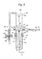
- the workpiece feeder is provided with a lifting means, indicated by the general reference numeral 60, at the window 18 of the table 16.
- the lifting means 60 has a pneumatic cylinder 62 in which is closely fitted a piston 64 mounted at an end of a connecting rod 66, the other end of which is connected to a movable platform 68.
- a pair of parallel guide rods 70 are rigidly connected to the platform 68 and slidably engage within bores 72 formed in guides 74 in order to guide the platform 68 during its vertical movement.
- the platform 68 is provided at its upper surface with a pair of projections 76 corresponding to the apertures 54 in the upper plate 48.
- the inlet of the air cylinder 62 is connected by a piping 78 to a suitable compressed air source, not shown.
- a stop mechanism shown by general reference numeral 80, is provided at a side of the table 16 in alignment with the window 18.
- the stop mechanism 80 includes a pillar 82 slidably mounted to the frame 10 and a U-shaped stop 84 bolted to the top of the pillar 82.
- the pillar 82 is provided at a side thereof with a rack 86 engaging with a pinion 88 mounted on a shaft 90 which is journalled on bearings 92 and 94 and is adapted to be rotated by a handle 96.
- a handle 96 By rotating the handle 96 in one or an other direction, it is possible to raise or lower the pillar 82 to adjust the level of the stop 84.
- the limit switch 44 engages with the leading end of the next pallet and interrupts the feed of electric power to the motor 30. Then, compressed air is supplied to the air cylinder 62 to move the piston 64 upward, causing the platform to move upwardly through the central opening 58 in the lower plate 46 of the pallet 40 until it comes into contact with the bottom of upper plate 48.
- the platform 68 with its projections 76 engaged within the apertures 54 of the upper plate 48, then lifts the upper plate 48 away from the lower plate 46 and further propels the upper plate together with a workpiece 98 placed thereon until the upper plate abuts against the stop 84, as shown by a ghost line in Fig. 5.
- This elevated position of the workpiece 98 represents the workpiece gripping station of the robot, not shown.
- the robot hand grips the workpiece on the upper plate and hands it over to a machine tool, not shown, arranged at the other side of the robot.
- the vertical position of the stop 84 may be adjusted by rotating the handle 96 so that the workpiece feeder can serve with a robot having a gripping station at different heights or to accommodate workpieces having different dimensions.
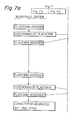
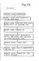
- the motion of the workpiece feeder and robot hand may be performed in the sequence shown in the flow-chart of F ig. 7.
- the robot's hand stands by at its workpiece gripping station.
- the platform ascends and is positioned by the stop at the gripping station.
- the robot hand grips the workpiece and the wrist of robot's hand turns 180° to load the workpiece on the machine tool.
- the platform descends and stands by until machining of the workpiece is completed, whereupon it ascends again and is positioned by the stop at the workpiece gripping station to receive the workpiece from the robot hand after machining.
- the platform descends back to its rest position and the conveyor is advanced by one pitch to bring another workpiece carrying pallet under the gripping position of the robot.
- the robot hand stands by for the next service.
- the above- described sequence may be ensured by first incorporating the sequence of the workpiece feeder into the program stored in the control unit of the robot and by controlling the actuators and sensors provided on the workpiece feeder through said control unit.
- the workpiece feeder may be provided with a simple sequence controller that controls the feeder in response to signals issued from the control unit of the robot.
- FIGs 8 and 9 illustrate another form of the stop mechanism shown in Fig. 6.
- the pillar 100 is provided at its top with a stop 102 and at a side thereof with a rack 104 similar to the example shown in Fig. 6, but in this example the pillar 100 has a scale 106 at the front face thereof.
- the pillar and rack assembly is slidably received within a channel l08 rigidly connected to the frame.
- the channel 108 is provided with slots 110 through which screws 112 are inserted.
- the screws 112 are screwed into threaded holes 114 provided in a toothed plate 116 having teeth 118 which are in mesh with the rack 104.
- the length l of the slot 110 is larger than the pitch P of the teeth 118 of the plate 116, so that the screws 112 may be positioned at any vertical position within the range of the pitch P.
- the screws 112 are released and the pillar 100 is moved together with the toothed plate 116 through a desired distance by reading the scale and by sliding the screws along the slots. Then, the screws are fastened to lock the toothed plate at a new position.
- the toothed plate may be disengaged from the associating rack if the stop is to be displaced through a distance larger than the length of pitch P.
- the conveyor is described as comprising the whole of the belt run thereof extending over the table.
- the conveyor may be of the type which has a portion of the upper belt run passing over the table but its lower belt run disposed under the table.
Landscapes
- Engineering & Computer Science (AREA)
- Mechanical Engineering (AREA)
- Feeding Of Workpieces (AREA)
- Specific Conveyance Elements (AREA)
- Intermediate Stations On Conveyors (AREA)
Applications Claiming Priority (2)
| Application Number | Priority Date | Filing Date | Title |
|---|---|---|---|
| JP100501/81 | 1981-06-30 | ||
| JP56100501A JPS584336A (ja) | 1981-06-30 | 1981-06-30 | ワ−ク供給装置 |
Publications (2)
| Publication Number | Publication Date |
|---|---|
| EP0069476A1 true EP0069476A1 (de) | 1983-01-12 |
| EP0069476B1 EP0069476B1 (de) | 1985-10-02 |
Family
ID=14275678
Family Applications (1)
| Application Number | Title | Priority Date | Filing Date |
|---|---|---|---|
| EP82303015A Expired EP0069476B1 (de) | 1981-06-30 | 1982-06-11 | Einrichtung zum Handhaben von Werkstücken |
Country Status (5)
| Country | Link |
|---|---|
| US (1) | US4492301A (de) |
| EP (1) | EP0069476B1 (de) |
| JP (1) | JPS584336A (de) |
| KR (1) | KR850000973B1 (de) |
| DE (1) | DE3266663D1 (de) |
Cited By (2)
| Publication number | Priority date | Publication date | Assignee | Title |
|---|---|---|---|---|
| EP0485223A3 (en) * | 1990-11-07 | 1993-03-03 | Heian Corporation | An automatic control system for a numerically controlled router |
| FR2691136A1 (fr) * | 1992-05-15 | 1993-11-19 | Remy Equipement | Convoyeur pour machine de conditionnement de récipients. |
Families Citing this family (37)
| Publication number | Priority date | Publication date | Assignee | Title |
|---|---|---|---|---|
| JPS6091856A (ja) * | 1983-10-22 | 1985-05-23 | Hitachi Kiden Kogyo Ltd | リニアパルスモ−タを用いた搬送装置 |
| US4598816A (en) * | 1984-08-06 | 1986-07-08 | Kutzli Carl R | Method and means for jigging workpiece for machining |
| US4693370A (en) * | 1984-10-22 | 1987-09-15 | Rca Corporation | Pallet |
| US4602499A (en) * | 1984-12-24 | 1986-07-29 | Scans Associates, Inc. | Flexible industrial system with quick change part holding means |
| US4723648A (en) * | 1985-03-14 | 1988-02-09 | Hi-Tec Seiko Company Ltd. | High speed rotational supporting device |
| US4721198A (en) * | 1985-11-13 | 1988-01-26 | Ando Electric Co., Ltd. | Probe card clamping and changing mechanism |
| DE3621604A1 (de) * | 1986-06-27 | 1988-03-10 | Kessler Kg Maschf | Spannvorrichtung fuer paletten |
| US5346058A (en) * | 1988-06-27 | 1994-09-13 | Axis U.S.A. Inc. | Automatic adjustment of pallet workpiece support members |
| US5255778A (en) * | 1988-06-27 | 1993-10-26 | Axis S.P.A. | Automatic adjustment of pallet workpiece support members |
| US5060781A (en) * | 1988-06-27 | 1991-10-29 | Axis U.S.A., Inc. | Apparatus for the automatic adjustment of pallet workpiece support members |
| US5115901A (en) * | 1988-06-27 | 1992-05-26 | Axis U.S.A., Inc. | Automatic adjustment of pallet workpiece support members |
| DE4019031C2 (de) * | 1990-06-14 | 1996-08-01 | Tetra Pak Gmbh | Vorrichtung zum Verdrehen von mittels einer Fördereinrichtung tranportierten Werkstückträgern mit Werkstücken und Verwendung einer solchen Vorrichtung |
| US5191958A (en) * | 1991-02-01 | 1993-03-09 | Giddings & Lewis, Inc. | Automatic framing system |
| US5348142A (en) * | 1993-07-26 | 1994-09-20 | Odawara Engineering Co., Ltd. | Adjustable pallet |
| US5685413A (en) * | 1995-09-12 | 1997-11-11 | Odawara Automation, Inc. | Adjustable pallet for supporting work pieces |
| US5658477A (en) * | 1995-11-22 | 1997-08-19 | Odawara Automation, Inc. | Method and apparatus for welding a stack of stator laminations |
| US5735219A (en) * | 1996-11-27 | 1998-04-07 | Odawara Automation, Inc. | Open base adjustable pallet for supporting work pieces |
| DE19758839B4 (de) * | 1997-09-06 | 2007-11-15 | Abb Patent Gmbh | Montagestation für den Zusammenbau von Komponenten |
| DE19744909C2 (de) * | 1997-09-06 | 2002-03-21 | Abb Patent Gmbh | Montageanlage für den Zusammenbau von Komponenten |
| US6517303B1 (en) | 1998-05-20 | 2003-02-11 | Applied Komatsu Technology, Inc. | Substrate transfer shuttle |
| US6215897B1 (en) | 1998-05-20 | 2001-04-10 | Applied Komatsu Technology, Inc. | Automated substrate processing system |
| US6176668B1 (en) * | 1998-05-20 | 2001-01-23 | Applied Komatsu Technology, Inc. | In-situ substrate transfer shuttle |
| US6604443B2 (en) | 2001-07-23 | 2003-08-12 | Newell Window Furnishings, Inc. | Blind and shade cutting center |
| US8499670B2 (en) * | 2001-07-23 | 2013-08-06 | Newell Window Furnishings, Inc. | Modular blind cutting center |
| US20040173066A1 (en) * | 2003-03-03 | 2004-09-09 | Joshua Abdollahzadeh | Blind cutting center with multi-speed saw |
| US7810418B2 (en) * | 2003-03-03 | 2010-10-12 | Newell Window Furnishings, Inc. | Automatically configurable blind cutting center |
| US7178439B2 (en) * | 2003-03-03 | 2007-02-20 | Newell Window Furnishings, Inc. | Blind cutting center |
| US7036412B2 (en) * | 2003-03-03 | 2006-05-02 | Newell Window Furnishings, Inc. | Blind cutting center with detachable vacuum bag |
| US20070239551A1 (en) * | 2006-03-30 | 2007-10-11 | Zeller Michelle G | Method and apparatus for a product ordering system |
| US7421886B1 (en) | 2007-06-15 | 2008-09-09 | Fox Michael A | Quick connect coupling test apparatus and method |
| US8256333B2 (en) * | 2007-07-31 | 2012-09-04 | Newell Window Furnishings, Inc. | Window covering sizing method and apparatus |
| US8322260B2 (en) | 2007-07-31 | 2012-12-04 | Newell Window Furnishings, Inc. | Window covering sizing method and apparatus |
| US7987754B2 (en) | 2007-07-31 | 2011-08-02 | Newell Window Furnishings, Inc. | Window covering sizing method and apparatus |
| US8839701B2 (en) * | 2007-07-31 | 2014-09-23 | Newell Window Furnishings, Inc. | Window covering sizing method and apparatus |
| US9427813B2 (en) * | 2007-07-31 | 2016-08-30 | Newell Window Furnishing, Inc. | Window covering sizing method and apparatus |
| US9266639B2 (en) | 2010-07-19 | 2016-02-23 | Newell Window Furnishings, Inc. | Blind packaging and methods of cutting window coverings |
| US8479925B2 (en) | 2010-07-19 | 2013-07-09 | Newell Window Furnishings, Inc. | Display system |
Citations (6)
| Publication number | Priority date | Publication date | Assignee | Title |
|---|---|---|---|---|
| US2463281A (en) * | 1947-01-08 | 1949-03-01 | Thomas M Kane | Dual turret conveyer |
| GB800584A (en) * | 1956-03-15 | 1958-08-27 | Dennis Albert Nayler | Improvements in and relating to wood planing machines |
| DE1552770A1 (de) * | 1966-08-18 | 1969-07-10 | Liebherr Dr Ing E H Hans | Einrichtung zur automatischen Beschickung von Werkzeugmaschinen |
| DE2444124A1 (de) * | 1974-09-14 | 1976-04-01 | Index Werke Kg Hahn & Tessky | Zusatzeinrichtung zum automatischen be- und/oder entladen von werkzeugmaschinen |
| US3998316A (en) * | 1974-05-10 | 1976-12-21 | Kamm Lawrence J | Manufacturing machine |
| DE2710661A1 (de) * | 1977-03-11 | 1978-09-14 | Index Werke Kg Hahn & Tessky | Einrichtung zum beladen und entladen einer arbeitsspindel von werkzeugmaschinen |
Family Cites Families (8)
| Publication number | Priority date | Publication date | Assignee | Title |
|---|---|---|---|---|
| US10191A (en) * | 1853-11-01 | Straw and grain separator | ||
| US374396A (en) * | 1887-12-06 | Elevator-stop | ||
| US1989039A (en) * | 1932-04-15 | 1935-01-22 | Filler Machine Company Inc | Capping mechanism |
| US2611473A (en) * | 1949-06-23 | 1952-09-23 | Int Harvester Co | Removable carrier tray for gear hardening apparatus |
| DE1195020B (de) * | 1963-02-23 | 1965-06-16 | Wuppermetall G M B H | Masselgiessmaschine mit absatzweise um eine senkrechte Achse umlaufendem Drehtisch |
| US3710711A (en) * | 1971-08-24 | 1973-01-16 | Webb Co | System for forming and handling annular rod bundles |
| US4049500A (en) * | 1974-05-10 | 1977-09-20 | Kamm Lawrence J | Manufacturing machine |
| IT1138808B (it) * | 1981-06-23 | 1986-09-17 | Rockwell Rimoldi Spa | Dispositivo prelevatore e posizionatore di pezzi di tessuto impilati |
-
1981
- 1981-06-30 JP JP56100501A patent/JPS584336A/ja active Pending
-
1982
- 1982-06-11 EP EP82303015A patent/EP0069476B1/de not_active Expired
- 1982-06-11 DE DE8282303015T patent/DE3266663D1/de not_active Expired
- 1982-06-21 US US06/390,560 patent/US4492301A/en not_active Expired - Fee Related
- 1982-06-30 KR KR8202924A patent/KR850000973B1/ko not_active Expired
Patent Citations (6)
| Publication number | Priority date | Publication date | Assignee | Title |
|---|---|---|---|---|
| US2463281A (en) * | 1947-01-08 | 1949-03-01 | Thomas M Kane | Dual turret conveyer |
| GB800584A (en) * | 1956-03-15 | 1958-08-27 | Dennis Albert Nayler | Improvements in and relating to wood planing machines |
| DE1552770A1 (de) * | 1966-08-18 | 1969-07-10 | Liebherr Dr Ing E H Hans | Einrichtung zur automatischen Beschickung von Werkzeugmaschinen |
| US3998316A (en) * | 1974-05-10 | 1976-12-21 | Kamm Lawrence J | Manufacturing machine |
| DE2444124A1 (de) * | 1974-09-14 | 1976-04-01 | Index Werke Kg Hahn & Tessky | Zusatzeinrichtung zum automatischen be- und/oder entladen von werkzeugmaschinen |
| DE2710661A1 (de) * | 1977-03-11 | 1978-09-14 | Index Werke Kg Hahn & Tessky | Einrichtung zum beladen und entladen einer arbeitsspindel von werkzeugmaschinen |
Cited By (2)
| Publication number | Priority date | Publication date | Assignee | Title |
|---|---|---|---|---|
| EP0485223A3 (en) * | 1990-11-07 | 1993-03-03 | Heian Corporation | An automatic control system for a numerically controlled router |
| FR2691136A1 (fr) * | 1992-05-15 | 1993-11-19 | Remy Equipement | Convoyeur pour machine de conditionnement de récipients. |
Also Published As
| Publication number | Publication date |
|---|---|
| DE3266663D1 (en) | 1985-11-07 |
| EP0069476B1 (de) | 1985-10-02 |
| KR840000338A (ko) | 1984-02-18 |
| KR850000973B1 (ko) | 1985-07-05 |
| US4492301A (en) | 1985-01-08 |
| JPS584336A (ja) | 1983-01-11 |
Similar Documents
| Publication | Publication Date | Title |
|---|---|---|
| US4492301A (en) | Workpiece feeder | |
| CN108584450B (zh) | 一种具有取料和堆叠功能的机械手 | |
| US5337594A (en) | Arrangement at press line | |
| EP0068674B1 (de) | Werkstückzuführeinrichtung | |
| KR102309360B1 (ko) | 가공물 자동 언로딩장치 | |
| EP0807482B1 (de) | Wechselvorrichtung für Messerhalter in einer Schneidpresse | |
| CN112122838B (zh) | 箱式房用全自动焊接装置 | |
| CN208369955U (zh) | 一种pcb板打钉包胶的自动化生产线 | |
| KR880000539B1 (ko) | 로보트 시스템 | |
| CN116161408B (zh) | 旋塞阀的全自动翻转装置及翻转方法 | |
| CN215755153U (zh) | 一种柔性折弯中心用基于机械手的上下料机构 | |
| JP3276474B2 (ja) | レーザ加工装置 | |
| CN119681608A (zh) | 一种轴承压装设备 | |
| CN218452742U (zh) | 一种用于哑铃生产的装配装置 | |
| CN115731758B (zh) | 一种盒盖的自动化加工装配实训系统 | |
| CN212737126U (zh) | 一种自动铆合设备 | |
| CN114473785A (zh) | 一种自动上下料装置及高精度磨床 | |
| CN211361545U (zh) | 自动上下料机和自动上下料装备 | |
| CN209830072U (zh) | 一种智能多功能独立式连线机械手 | |
| JPH054283B2 (de) | ||
| CN121199652B (zh) | 一种双线供料集成装配的自动化系统及装配方法 | |
| CN224128653U (zh) | 一种火焰切割机零部件加工用镗床 | |
| CN220722787U (zh) | 一种用于磨抛的自动双通道转架机设备 | |
| CN213917263U (zh) | 滤板输送机构及加工生产线 | |
| CN213646035U (zh) | 一种转盘式铣台 |
Legal Events
| Date | Code | Title | Description |
|---|---|---|---|
| PUAI | Public reference made under article 153(3) epc to a published international application that has entered the european phase |
Free format text: ORIGINAL CODE: 0009012 |
|
| 17P | Request for examination filed |
Effective date: 19820616 |
|
| AK | Designated contracting states |
Designated state(s): DE FR GB IT |
|
| ITF | It: translation for a ep patent filed | ||
| GRAA | (expected) grant |
Free format text: ORIGINAL CODE: 0009210 |
|
| AK | Designated contracting states |
Designated state(s): DE FR GB IT |
|
| REF | Corresponds to: |
Ref document number: 3266663 Country of ref document: DE Date of ref document: 19851107 |
|
| ET | Fr: translation filed | ||
| PLBE | No opposition filed within time limit |
Free format text: ORIGINAL CODE: 0009261 |
|
| STAA | Information on the status of an ep patent application or granted ep patent |
Free format text: STATUS: NO OPPOSITION FILED WITHIN TIME LIMIT |
|
| 26N | No opposition filed | ||
| PGFP | Annual fee paid to national office [announced via postgrant information from national office to epo] |
Ref country code: FR Payment date: 19890526 Year of fee payment: 8 |
|
| PGFP | Annual fee paid to national office [announced via postgrant information from national office to epo] |
Ref country code: DE Payment date: 19890626 Year of fee payment: 8 |
|
| ITTA | It: last paid annual fee | ||
| PGFP | Annual fee paid to national office [announced via postgrant information from national office to epo] |
Ref country code: GB Payment date: 19890630 Year of fee payment: 8 |
|
| PG25 | Lapsed in a contracting state [announced via postgrant information from national office to epo] |
Ref country code: GB Effective date: 19900611 |
|
| GBPC | Gb: european patent ceased through non-payment of renewal fee | ||
| PG25 | Lapsed in a contracting state [announced via postgrant information from national office to epo] |
Ref country code: FR Effective date: 19910228 |
|
| PG25 | Lapsed in a contracting state [announced via postgrant information from national office to epo] |
Ref country code: DE Effective date: 19910301 |
|
| REG | Reference to a national code |
Ref country code: FR Ref legal event code: ST |