EP0069483A2 - Industrieroboter - Google Patents
Industrieroboter Download PDFInfo
- Publication number
- EP0069483A2 EP0069483A2 EP82303081A EP82303081A EP0069483A2 EP 0069483 A2 EP0069483 A2 EP 0069483A2 EP 82303081 A EP82303081 A EP 82303081A EP 82303081 A EP82303081 A EP 82303081A EP 0069483 A2 EP0069483 A2 EP 0069483A2
- Authority
- EP
- European Patent Office
- Prior art keywords
- robot
- motion unit
- vertical
- industrial robot
- rotary motion
- Prior art date
- Legal status (The legal status is an assumption and is not a legal conclusion. Google has not performed a legal analysis and makes no representation as to the accuracy of the status listed.)
- Granted
Links
- 210000000707 wrist Anatomy 0.000 claims description 5
- 238000009429 electrical wiring Methods 0.000 description 4
- 239000012530 fluid Substances 0.000 description 3
- 238000010276 construction Methods 0.000 description 2
- 239000000463 material Substances 0.000 description 1
- 229910001220 stainless steel Inorganic materials 0.000 description 1
- 239000010935 stainless steel Substances 0.000 description 1
Images
Classifications
-
- B—PERFORMING OPERATIONS; TRANSPORTING
- B25—HAND TOOLS; PORTABLE POWER-DRIVEN TOOLS; MANIPULATORS
- B25J—MANIPULATORS; CHAMBERS PROVIDED WITH MANIPULATION DEVICES
- B25J1/00—Manipulators positioned in space by hand
-
- B—PERFORMING OPERATIONS; TRANSPORTING
- B25—HAND TOOLS; PORTABLE POWER-DRIVEN TOOLS; MANIPULATORS
- B25J—MANIPULATORS; CHAMBERS PROVIDED WITH MANIPULATION DEVICES
- B25J18/00—Arms
- B25J18/02—Arms extensible
-
- B—PERFORMING OPERATIONS; TRANSPORTING
- B25—HAND TOOLS; PORTABLE POWER-DRIVEN TOOLS; MANIPULATORS
- B25J—MANIPULATORS; CHAMBERS PROVIDED WITH MANIPULATION DEVICES
- B25J19/00—Accessories fitted to manipulators, e.g. for monitoring, for viewing; Safety devices combined with or specially adapted for use in connection with manipulators
- B25J19/0025—Means for supplying energy to the end effector
- B25J19/0029—Means for supplying energy to the end effector arranged within the different robot elements
-
- Y—GENERAL TAGGING OF NEW TECHNOLOGICAL DEVELOPMENTS; GENERAL TAGGING OF CROSS-SECTIONAL TECHNOLOGIES SPANNING OVER SEVERAL SECTIONS OF THE IPC; TECHNICAL SUBJECTS COVERED BY FORMER USPC CROSS-REFERENCE ART COLLECTIONS [XRACs] AND DIGESTS
- Y10—TECHNICAL SUBJECTS COVERED BY FORMER USPC
- Y10T—TECHNICAL SUBJECTS COVERED BY FORMER US CLASSIFICATION
- Y10T74/00—Machine element or mechanism
- Y10T74/18—Mechanical movements
- Y10T74/18568—Reciprocating or oscillating to or from alternating rotary
- Y10T74/18576—Reciprocating or oscillating to or from alternating rotary including screw and nut
- Y10T74/18648—Carriage surrounding, guided by, and primarily supported by member other than screw [e.g., linear guide, etc.]
Definitions
- the present invention relates to an industrial robot and in particular to an improvement in the construction of an industrial robot of the type wherein a rotary motion unit of a robot motion assembly supporting a robot arm and a robot hand is arranged on a vertical motion unit of the robot movable assembly.
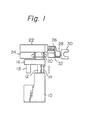
- a conventional industrial robot of the above-described type is provided with, as illustrated in Fig. 1, a vertical feed mechanism mounted on a robot base 10 and adapted to drive a robot motion assembly having a robot hand 30 vertically along a vertical guide 12 extending upward from the robot base 10.
- the robot motion assembly comprises a rotation drive means 16 including therein a rotation drive mechanism, a rotation drive motor 18, a bearing box 20, a robot housing 22 mounted on the bearing box 20, a drive motor 24 attached to the robot housing 22 for driving the stretching and retracting of a horizontal robot arm 26 extending transversely from the robot housing 22, a robot wrist 28 attached to an outer end of the horizontal robot arm 26, a robot hand 30 attached to a free end of the robot wrist 28, and a wrist-rotating drive motor 32.
- the conventional industrial robot has an arrangement in which a rotary motion unit having a vertically extending rotating axis is disposed on a vertical motion-unit having a vertical motion axis and a robot arm stretching and retracting mechanism for stretching and retracting the robot arm 26 is disposed in the rotary motion unit.
- Reference numeral 14 designates the rod of a load-compensating cylinder provided within the robot base 10 for reducing the load applied to the vertical feed mechanism by counterbalancing a downward load produced by the weights of the rotation drive mechanism, the robot arm stretching and retracting mechanism, and the workpiece gripped by the robot hand 30.
- An object of the present invention is therefore to provide an industrial robot having an improved structure capable of overcoming the disadvantages of the conventional industrial robot in respect to the electric wirings and pipings.
- Another object of the present invention is to provide an industrial robot having such a construction that the arranging of the electric wirings and pipings during the assembling of the industrial robot is made easier as well as less expensive due to the use of a minimum amount of members and materials and the reliability of the robot is enhanced.
- an industrial robot having a robot hand attached to a horizontal robot arm by means of a robot wrist comprises a stationary robot base formed as the lowermost element of the industrial robot, a vertical motion unit arranged on the stationary robot base and including a vertical feed mechanism and a vertical guide fixedly standing on the robot base, a rotary motion unit mounted on the vertical motion unit and including therein a rotation drive mechanism, housing means mounted on the rotary motion unit for supporting therein the horizontal arm, and hollow structure means vertically extending through the vertical motion unit and the rotary motion unit for defining therein a vertical cavity formed as a wiring and piping space.
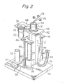
- two vertical guides 44 are fixed to a robot base 42, which is the lowermost element of the industrial robot according to the present invention.
- a plate 46 is fixed to the respective upper ends of the two vertical guides 44.
- a hollow frame member 48 formed as the movable part of the vertical motion unit of the robot is arranged so that it is up and down guided by the two guides 44. That is, the slides 50 of the hollow frame member 4 8 are fitted on the vertical guides 44.
- the hollow frame member 48 is shaped in a box-like member having a cavity vertically extending through the interior of the box-like member. The cavity of the hollow frame member 48 is provided so as to be used as a wiring and piping space.
- the vertical motion unit is provided with a drive motor 52 which is fixed to the robot base 42 by means of a bracket 54.
- the drive motor 52 drives, by means of a belt-and--pulley mechanism 56, a vertical feed screw 58 which is rotatably supported between the robot base 42 and the plate 46. That is, the feed screw 58 rotates about its own vertical axis when driven by the drive motor 52.
- the drive motor 52 per se is operated by a robot controller (not illustrated in Fig. 2).
- the vertical feed screw 58 is engaged in a thread-like fashion with an interlocking member 60 having an internal screw thread and projecting from one of the slides 50 of the hollow frame member 48.
- the hollow frame member 48 of the vertical motion unit is moved up and down along the vertical guides 44 in the direction indicated by the double-headed arros "A" while the feed screw 58 is rotated by the drive motor 52 since the vertical feed action of the feed screw 58 works on the interlocking member 60.
- An upper support plate 62 for supporting a rotary motion unit is fixed to the hollow frame member 48 at the upper end thereof.
- a tubular member 64 is rotatably mounted on the upper support plate 62 by means of a suitable rotary bearing means for rotation in the direction indicated by the double-headed arrow "B"..
- the tubular member 64 is disposed so as to be substantially in alignment with the hollow frame member 48 of the vertical motion unit.
- the tubular member 64 has therein a through-bore which is interconnected, via the bore of the upper plate 62, with and is substantially coaxial with the vertically extending cavity of the hollow frame member 46.
- a gear element 66 is mounted on the rotatable tubular member 64 at a lower part thereof and is engaged with an intermediate gear 68 which is also engaged with a pinion 74 attached to the output shaft of the rotation drive means consisting of a drive motor 70 and a reduction gear 72.
- the intermediate gear 68 is not an indispensable member and can be omitted. From Fig. 2, it will now be understood that the hollow frame member 48 and the tubular member 64 form a vertical hollow structure in the industrial robot.
- the transverse stretching and retracting mechanism is not illustrated in Fig. 2. However, it comprises a robot housing, a robot arm, a robot wrist, and a robot hand and is mounted on the rotatable tubular member 64 of the rotary motion unit at the upper end thereof in a manner similar to that in the conventional industrial robot illustrated in Fig. 1. From the foregoing description of the embodiment of Fig. 2, it will be understood that according to the present invention, a hollow structure formed by the hollow frame member 48 of the vertical motion unit disposed on the robot base 42 and the rotatable tubular member 64 of the rotary motion unit disposed on the vertical motion unit provides therein a wiring and piping space.
- the arrangement of electrical wiring cables 76 and piping for the distribution of a working fluid through the wiring and piping space from the lower part to the upper part thereof enables any wiring and piping from around the exterior of the industrial robot to be eliminated, and at the same time, the possibility of the wiring cables 76 and the piping being damaged as a result of interference from outside machines and equipment arranged around the industrial robot is eliminated. Furthermore, the external appearance of the industrial robot is improved.
- any twisting of the wiring cables 76 due to the rotation of the rotary motion unit is limited to the lowest degree if the electrical wiring cables,76 are arranged so as to run along the axis of rotation of the tubular member 64 within the wiring and piping space of the member 64.
- the piping is not connected directly to the rotary motion unit since it is arranged through the wiring and piping space so as to supply a working fluid, such as pressurized air, to the robot hand. Therefore, the piping is not subjected to twisting which occurs in the wiring cables 76.
- the arrangement of the wiring and piping through the wiring and piping space defined in the hollow structure of the present invention allows the omission of special holding or clamping members employed in the conventional industrial robot for providing suitable surplus lengths for the electrical wiring cables and the piping, simplifies the wiring and piping operation during the assembling of an industrial robot, and reduces the cost of the industrial robot.
Landscapes
- Engineering & Computer Science (AREA)
- Robotics (AREA)
- Mechanical Engineering (AREA)
- Manipulator (AREA)
Applications Claiming Priority (2)
| Application Number | Priority Date | Filing Date | Title |
|---|---|---|---|
| JP56099740A JPS584376A (ja) | 1981-06-29 | 1981-06-29 | 工業用ロボツト |
| JP99740/81 | 1981-06-29 |
Publications (3)
| Publication Number | Publication Date |
|---|---|
| EP0069483A2 true EP0069483A2 (de) | 1983-01-12 |
| EP0069483A3 EP0069483A3 (en) | 1984-05-09 |
| EP0069483B1 EP0069483B1 (de) | 1987-03-25 |
Family
ID=14255408
Family Applications (1)
| Application Number | Title | Priority Date | Filing Date |
|---|---|---|---|
| EP82303081A Expired EP0069483B1 (de) | 1981-06-29 | 1982-06-14 | Industrieroboter |
Country Status (6)
| Country | Link |
|---|---|
| US (1) | US4466769A (de) |
| EP (1) | EP0069483B1 (de) |
| JP (1) | JPS584376A (de) |
| KR (1) | KR850000550B1 (de) |
| DE (1) | DE3275819D1 (de) |
| SU (1) | SU1331420A3 (de) |
Cited By (6)
| Publication number | Priority date | Publication date | Assignee | Title |
|---|---|---|---|---|
| EP0092358A3 (en) * | 1982-04-21 | 1984-05-23 | Fanuc Ltd | A swivel device |
| FR2539662A1 (fr) * | 1983-01-24 | 1984-07-27 | Mitsubishi Electric Corp | Dispositif manipulateur automatique articule, notamment pour soudage a l'arc |
| EP0154825A1 (de) * | 1984-03-12 | 1985-09-18 | Kabushiki Kaisha Sankyo Seiki Seisakusho | Hebekopf eines Dreharmes eines Montage-Roboters |
| US4568238A (en) * | 1982-10-12 | 1986-02-04 | Toyoda Koki Kabushiki Kaisha | Horizontal multi-link type robot |
| US4659279A (en) * | 1984-12-24 | 1987-04-21 | Gmf Robotics Corporation | Robot with improved cable routing and clamping |
| CN103921161A (zh) * | 2014-04-15 | 2014-07-16 | 江苏优创数控设备有限公司 | 一种水平移动双臂取放工件机械手 |
Families Citing this family (11)
| Publication number | Priority date | Publication date | Assignee | Title |
|---|---|---|---|---|
| JPS60110605A (ja) * | 1983-10-18 | 1985-06-17 | 四国化工機株式会社 | 包装機械における横シ−ル装置 |
| US4616713A (en) * | 1984-11-29 | 1986-10-14 | Shattuck Thomas G | Blade adjustment device for sod cutting machine |
| JPS6263086A (ja) * | 1985-09-10 | 1987-03-19 | フアナツク株式会社 | 工業用ロボツトにおけるブレ−キ構造 |
| FR2588129B1 (fr) * | 1985-10-01 | 1990-06-01 | Peugeot Cycles | Motoreducteur pour l'entrainement simultane de deux organes |
| US4696197A (en) * | 1986-04-11 | 1987-09-29 | Lockheed Corporation | System for counterbalancing tool mount loads in a machine tool |
| JPH02142915U (de) * | 1989-05-02 | 1990-12-04 | ||
| JP2576282B2 (ja) * | 1990-11-15 | 1997-01-29 | 三菱電機株式会社 | 産業用ロボット |
| US5178512A (en) * | 1991-04-01 | 1993-01-12 | Equipe Technologies | Precision robot apparatus |
| US5769184A (en) * | 1996-09-27 | 1998-06-23 | Brooks Automation, Inc. | Coaxial drive elevator |
| JP4971063B2 (ja) * | 2007-07-27 | 2012-07-11 | 株式会社ダイヘン | 搬送装置 |
| CN104942794A (zh) * | 2015-07-01 | 2015-09-30 | 西北工业大学(张家港)智能装备技术产业化研究院有限公司 | 一种送料机器人 |
Family Cites Families (11)
| Publication number | Priority date | Publication date | Assignee | Title |
|---|---|---|---|---|
| US3247978A (en) * | 1962-12-12 | 1966-04-26 | Programmed & Remote Syst Corp | Manipulator hand |
| US3543947A (en) * | 1968-07-30 | 1970-12-01 | George C Devol | Constant-aim work head |
| CA922331A (en) * | 1970-02-20 | 1973-03-06 | C. Devol George | Article transfer and orienting means and method |
| US3805629A (en) * | 1972-06-01 | 1974-04-23 | Usm Corp | Devices for linear and rotational movements |
| JPS5345986B2 (de) * | 1973-07-31 | 1978-12-11 | ||
| US3935950A (en) * | 1973-09-04 | 1976-02-03 | Quality Steel Fabricators, Inc. | Industrial robot |
| DE7616495U1 (de) * | 1976-05-22 | 1976-11-25 | Kupka, Dieter Helmut, 6570 Kirn | Ruehrwerk mit hubwerk fuer laeuterbottiche |
| JPS5912419B2 (ja) * | 1976-12-16 | 1984-03-23 | 株式会社東芝 | テ−ブル装置 |
| JPS5623031U (de) * | 1979-04-08 | 1981-03-02 | ||
| FR2492304A1 (fr) * | 1980-10-17 | 1982-04-23 | Commissariat Energie Atomique | Ensemble de telemanipulation monte sur une plate-forme mobile et comportant un ensemble porteur telescopique retractable a l'interieur d'une hotte etanche, et procede de mise en place sur une enceinte |
| US4392776A (en) * | 1981-05-15 | 1983-07-12 | Westinghouse Electric Corp. | Robotic manipulator structure |
-
1981
- 1981-06-29 JP JP56099740A patent/JPS584376A/ja active Granted
-
1982
- 1982-06-14 EP EP82303081A patent/EP0069483B1/de not_active Expired
- 1982-06-14 DE DE8282303081T patent/DE3275819D1/de not_active Expired
- 1982-06-18 US US06/389,882 patent/US4466769A/en not_active Expired - Fee Related
- 1982-06-28 SU SU823457041A patent/SU1331420A3/ru active
- 1982-06-29 KR KR8202906A patent/KR850000550B1/ko not_active Expired
Cited By (7)
| Publication number | Priority date | Publication date | Assignee | Title |
|---|---|---|---|---|
| EP0092358A3 (en) * | 1982-04-21 | 1984-05-23 | Fanuc Ltd | A swivel device |
| US4568238A (en) * | 1982-10-12 | 1986-02-04 | Toyoda Koki Kabushiki Kaisha | Horizontal multi-link type robot |
| FR2539662A1 (fr) * | 1983-01-24 | 1984-07-27 | Mitsubishi Electric Corp | Dispositif manipulateur automatique articule, notamment pour soudage a l'arc |
| GB2134074A (en) * | 1983-01-24 | 1984-08-08 | Mitsubishi Electric Corp | Articulated robot |
| EP0154825A1 (de) * | 1984-03-12 | 1985-09-18 | Kabushiki Kaisha Sankyo Seiki Seisakusho | Hebekopf eines Dreharmes eines Montage-Roboters |
| US4659279A (en) * | 1984-12-24 | 1987-04-21 | Gmf Robotics Corporation | Robot with improved cable routing and clamping |
| CN103921161A (zh) * | 2014-04-15 | 2014-07-16 | 江苏优创数控设备有限公司 | 一种水平移动双臂取放工件机械手 |
Also Published As
| Publication number | Publication date |
|---|---|
| SU1331420A3 (ru) | 1987-08-15 |
| KR840000335A (ko) | 1984-02-18 |
| DE3275819D1 (en) | 1987-04-30 |
| JPS584376A (ja) | 1983-01-11 |
| KR850000550B1 (ko) | 1985-04-26 |
| EP0069483B1 (de) | 1987-03-25 |
| JPS6315114B2 (de) | 1988-04-02 |
| EP0069483A3 (en) | 1984-05-09 |
| US4466769A (en) | 1984-08-21 |
Similar Documents
| Publication | Publication Date | Title |
|---|---|---|
| EP0069483A2 (de) | Industrieroboter | |
| US4289441A (en) | Industrial robot | |
| US4543033A (en) | Industrial robot | |
| AU2020299731A1 (en) | Robotic manipulator for underground coal mining | |
| US4522555A (en) | Handling apparatus | |
| US4534697A (en) | Transfer device for robots | |
| US4151390A (en) | Tool holder head, particularly for welding yokes and guns | |
| JPH0783987B2 (ja) | 種々の使用目的のための産業・ロボツト | |
| CA1209172A (en) | Robotic manipulator arm | |
| US4540332A (en) | Swivel device | |
| US5014542A (en) | Automatic machine tool head designed to increase the number of machine operating axes | |
| US4699563A (en) | Horizontal articulated robot | |
| CN113146216B (zh) | 一种定位垫片螺丝机 | |
| CN219925099U (zh) | 焊接设备 | |
| CN107186498B (zh) | 一种用于飞机翼盒数字化装配的五轴数控制孔机床 | |
| US7963188B2 (en) | Industrial robot having a suspended unit | |
| CN221391095U (zh) | 一种粗纱卸纱机械手 | |
| CN219703972U (zh) | 一种立式同步旋转焊接平台 | |
| US5194716A (en) | Robotic welding device with counterweight | |
| JP2652963B2 (ja) | トランスファー装置 | |
| JP3811999B2 (ja) | ねじ締め装置 | |
| CN218313536U (zh) | 一种具有三轴工业机器人的上下料设备 | |
| JPH0536197B2 (de) | ||
| KR820002362B1 (ko) | 산업용 로봇 | |
| CN220617689U (zh) | 一种电气控制柜料板加工用传送装置 |
Legal Events
| Date | Code | Title | Description |
|---|---|---|---|
| PUAI | Public reference made under article 153(3) epc to a published international application that has entered the european phase |
Free format text: ORIGINAL CODE: 0009012 |
|
| 17P | Request for examination filed |
Effective date: 19820622 |
|
| AK | Designated contracting states |
Designated state(s): DE FR GB IT |
|
| PUAL | Search report despatched |
Free format text: ORIGINAL CODE: 0009013 |
|
| AK | Designated contracting states |
Designated state(s): DE FR GB IT |
|
| GRAA | (expected) grant |
Free format text: ORIGINAL CODE: 0009210 |
|
| AK | Designated contracting states |
Kind code of ref document: B1 Designated state(s): DE FR GB IT |
|
| ITF | It: translation for a ep patent filed | ||
| ET | Fr: translation filed | ||
| REF | Corresponds to: |
Ref document number: 3275819 Country of ref document: DE Date of ref document: 19870430 |
|
| PLBE | No opposition filed within time limit |
Free format text: ORIGINAL CODE: 0009261 |
|
| STAA | Information on the status of an ep patent application or granted ep patent |
Free format text: STATUS: NO OPPOSITION FILED WITHIN TIME LIMIT |
|
| 26N | No opposition filed | ||
| PG25 | Lapsed in a contracting state [announced via postgrant information from national office to epo] |
Ref country code: FR Free format text: LAPSE BECAUSE OF NON-PAYMENT OF DUE FEES Effective date: 19890228 |
|
| PG25 | Lapsed in a contracting state [announced via postgrant information from national office to epo] |
Ref country code: DE Effective date: 19890301 |
|
| REG | Reference to a national code |
Ref country code: FR Ref legal event code: ST |
|
| PGFP | Annual fee paid to national office [announced via postgrant information from national office to epo] |
Ref country code: GB Payment date: 19910531 Year of fee payment: 10 |
|
| PG25 | Lapsed in a contracting state [announced via postgrant information from national office to epo] |
Ref country code: GB Effective date: 19920614 |
|
| GBPC | Gb: european patent ceased through non-payment of renewal fee |
Effective date: 19920614 |