EP0069501A2 - Verbesserungen in elektrolytischen Reduktionzellen - Google Patents
Verbesserungen in elektrolytischen Reduktionzellen Download PDFInfo
- Publication number
- EP0069501A2 EP0069501A2 EP82303225A EP82303225A EP0069501A2 EP 0069501 A2 EP0069501 A2 EP 0069501A2 EP 82303225 A EP82303225 A EP 82303225A EP 82303225 A EP82303225 A EP 82303225A EP 0069501 A2 EP0069501 A2 EP 0069501A2
- Authority
- EP
- European Patent Office
- Prior art keywords
- cell
- molten
- baffle
- metal
- electrolytic reduction
- Prior art date
- Legal status (The legal status is an assumption and is not a legal conclusion. Google has not performed a legal analysis and makes no representation as to the accuracy of the status listed.)
- Granted
Links
Images

Classifications
-
- C—CHEMISTRY; METALLURGY
- C25—ELECTROLYTIC OR ELECTROPHORETIC PROCESSES; APPARATUS THEREFOR
- C25C—PROCESSES FOR THE ELECTROLYTIC PRODUCTION, RECOVERY OR REFINING OF METALS; APPARATUS THEREFOR
- C25C3/00—Electrolytic production, recovery or refining of metals by electrolysis of melts
- C25C3/06—Electrolytic production, recovery or refining of metals by electrolysis of melts of aluminium
- C25C3/08—Cell construction, e.g. bottoms, walls, cathodes
Definitions
- the present invention relates to electrolytic reduction cells for the production of metal by the electrolysis of a metal-bearing substance in a molten electrolyte, which is less dense than the product metal.
- a typical electrolytic reduction cell for the production of aluminium is rectangular in shape.
- the cell includes one or more suspended anodes and a cathode structure, comprising carbon blocks, forming the floor of the cell, in electrical connection with transverse steel current collector rods or bars which are connected to cathode bus bars extending lengthwise of the cell.
- a pool of the molten product metal collects on the floor of the cell and forms a liquid cathode, from which a batch of molten metal is withdrawn at intervals.
- the molten aluminium layer is more conductive than the carbon floor blocks, transverse components of the cathode current occur in the molten metal layer and these interact with the electromagnetic fields in the cell, resulting from the very heavy currents in the electrical conductors associated with the process.
- the electromagnetic forces result in the establishment of wave motion in the molten metal. Wave motion may also be induced in the molten metal by the evolution of gas bubbles.
- an electrolytic reduction cell in accordance with the present invention is provided with at least one essentially linear transversely extending baffle member in which energy absorbing restricted flow channels are formed.
- Such flow channels may be provided between aligned spaced elements which together constitute a single baffle member or may be in the form of apertures in a unitary baffle member.
- baffle member or members are essentially in the form of long, low massive members, which are stronger and more resistant to accidental damage than the unsupported collector bars of U.S. Patent No. 3,093,570.
- baffle members extend upward from the floor by only a small amount and the height of such members is preferably such that they remain wholly submerged in the molten metal at all stages of the normal cell operating cycle. In such event it would be sufficient for such members to be constructed from carbon or alumina or other refractory material resistant to attack by molten aluminium. Where there is a risk that the baffle members may be partially exposed to the molten electrolyte during the cell operation, they should be constructed from a material which is resistant to attack by the molten electrolyte, as well as to attack by the molten aluminium metal.
- the baffle members be constructed of a refractory material resistant to attack by electrolyte, as well as resistant to molten aluminium.
- the baffle members must either be formed of a material more dense than the product metal or be attached to the cell structure.
- a titanium boride refractory is one example of a material found very suitable for the present purpose because of its resistance to attack by both molten aluminium and the molten electrolyte. Because titanium boride is electroconductive it causes little disturbance of the current pattern in the pool of molten metal and this may be advantageous in some instances.
- baffle members exert a damping effect on flowing molten metal to absorb its kinetic energy and thus reduce the amplitude of its wave motion.
- the cell in conjunction with the metal flow-restricting baffle members, is provided with means for maintaining the volume of molten metal in the cell at a substantially constant value.
- the cell may be provided with one or more selective filters, operative to permit passage of molten metal and to restrict passage of molten electrolyte, as described in co-pending British Patent Application No. 6119589.
- selective filter(s) is/are arranged to allow molten metal to be withdrawn from the pool of molten metal on a continuous basis.
- sludge is composed, at least in substantial part, of alumina feed material which has failed to dissolve in the cell electrolyte and has passed into and through the molten metal, since alumina is more dense than molten aluminium and drags molten electrolyte into the bottom of the cell.
- the cell is preferably constructed so that sludge may migrate to the sides and/or ends of the cell to permit such reabsorption to take place.
- the baffle members are arranged transversely of the cell and located so as to extend outwardly of and/or somewhat inwardly of the edges of the anode shadow area at positions where (in the absence of the baffle members) the metal flow velocity is at its maximum.
- the baffle members are preferably arranged substantially perpendicular to the direction of metal flow.
- each baffle member Since the purpose of the baffle members is to establish tranquil, relatively wave-free conditions in the molten metal, each baffle member is associated with energy-absorbing devices, such as restricted apertures extending along the direction of the metal flow to exert a damping action on such flow.
- Each baffle member should have a large thickness to height ratio (height being the vertical extent of the baffle member above the floor of the cell, although a substantial part of the baffle member may be embedded in the floor of the cell). The thickness/height ratio is preferably at least 1/1.
- the baffle members may be formed with circular apertures in a size range of 50-50 mm. and occupying 10-50% of the effective surface of each baffle member.
- baffle members may be made from a thick honeycomb material having triangular, square or other-shaped apertures of sizes in the above stated range and occupying up to 70% of the surface area of the honeycomb.
- each baffle member may be formed of a series of separate blocks arranged in side-by-side relation to present relatively narrow flow-restricting channels between adjacent blocks to perform the same function as the aforesaid apertures.
- blocks may be simple rectangular blocks but may take other forms better adapted to absorb the kinetic energy of the molten metal under the particular conditions of the cell.
- the blocks may be trapezoidal in profile.
- the faces of the blocks presented to the flowing metal may be inclined forwardly or backwardly in relation to the vertical.
- longitudinal baffle members in addition to transverse baffle members, for wave-damping purposes in the anode shadow area, it is desirable that such longitudinal baffle members should be mounted. in such a manner as to permit an unobstructed lateral flow of sludge beneath each longitudinal baffle member to the side areas of the cell for the reasons explained above.' This may conveniently be achieved by supporting such longitudinal baffle members on the transverse baffle members with the bottom edge surface of the longitudinal baffle members slightly raised above the floor of the cell.
- the cell employs two parallel rows of anodes and feed alumina is supplied to the cell by breaking the crust between the anode rows
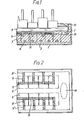
- the cell comprises a rectangular steel shell 1, lined with electrical and thermal insulation 2.
- the cell is provided with a conventional cathode floor structure formed of carbon blocks 3, electrically connected to steel collector bars 4 which carry the cathode current to bus bars (not shown) extending along the two longitudinal sides of the cell in the well known manner.
- the cell is provided with parallel rows of prebake anodes 5, the shadow areas of which are indicated at 6 in Figure 2. In operation there is a pool of molten metal 7 in the bottom of the cell and an overlying layer of molten fluoride electrolyte 8.
- Transverse baffle members 9 are recessed into the carbon floor blocks 3 at positions within the anode shadow areas and these baffle members may have portions 9' extending outwardly into the frozen electrolyte 10 at the sides of the cell (not shown in Figure 2).
- the transverse baffle members 9 may support longitudinal baffle members 11 with lower edges of such longitudinal baffle members spaced slightly away from the floor to permit sludge to move transversely beneath.
- baffle members 9 may take any of the forms indicated in Figures 4, 5 and 6.
- transverse dotted line 20 indicates the top surface of the cell floor 3.
- the part of the baffle member beneath the dotted line is intended to be embedded in the cell floor.
- a baffle member having an overall height of 10 - 15 cms is formed with two rows of apertures 21, having a diameter of about 3 cms. the apertures forming about 20% of the exposed area of the baffle member.
- the baffle member is formed of separate rectangular blocks 22 having a width of about 10 - 15 cms. and spaced apart by a distance of 2 - 3 cms. to provide energy-absorbing flow channels 23.
- the baffle members are comprised of a honeycomb section in which apertures 24 are squares of 1 - 2 cms. width and form about 70% of the frontal area of the baffle member.
- the thickness of the baffle members is of the order of 10 - 15 cms. or more to provide desirable strength.
- Longitudinal baffle members 11 may take the same general form as those shown in Figures 4, 5 or 6.
- the height of the baffle member 11 will be reduced so as to permit transverse flow beneath it while retaining the top edge at substantially the same level as the top edge of the baffle members 9, whereas when the baffle member 11 takes the form of that shown in Figure 5, the separate blocks are mounted in the floor and the channels 23 permit transverse sludge transport.
- baffle members results in a substantial reduction in the amplitude of the wave motion in the metal pool and increased stability at the interface between the molten metal 7 and the electrolyte 8.
- baffle members 9 and 11 are formed from material which is resistant to attack by molten aluminium metal and preferably have at least an external skin of a refractory hard metal such as titanium diboride so as to render them resistant to attack by the cell electrolyte.
- Such baffle members may be electroconductive or substantially -non-conductive.
Landscapes
- Chemical & Material Sciences (AREA)
- Engineering & Computer Science (AREA)
- Chemical Kinetics & Catalysis (AREA)
- Electrochemistry (AREA)
- Materials Engineering (AREA)
- Metallurgy (AREA)
- Organic Chemistry (AREA)
- Electrolytic Production Of Metals (AREA)
- Secondary Cells (AREA)
- Battery Electrode And Active Subsutance (AREA)
- Electrolytic Production Of Non-Metals, Compounds, Apparatuses Therefor (AREA)
- Primary Cells (AREA)
- Electrodes For Compound Or Non-Metal Manufacture (AREA)
- Manufacture And Refinement Of Metals (AREA)
- Water Treatment By Electricity Or Magnetism (AREA)
- Photovoltaic Devices (AREA)
Priority Applications (1)
| Application Number | Priority Date | Filing Date | Title |
|---|---|---|---|
| AT82303225T ATE17135T1 (de) | 1981-06-25 | 1982-06-21 | Verbesserungen in elektrolytischen reduktionzellen. |
Applications Claiming Priority (2)
| Application Number | Priority Date | Filing Date | Title |
|---|---|---|---|
| GB8119590 | 1981-06-25 | ||
| GB8119590 | 1981-06-25 |
Publications (3)
| Publication Number | Publication Date |
|---|---|
| EP0069501A2 true EP0069501A2 (de) | 1983-01-12 |
| EP0069501A3 EP0069501A3 (en) | 1983-04-13 |
| EP0069501B1 EP0069501B1 (de) | 1985-12-27 |
Family
ID=10522793
Family Applications (1)
| Application Number | Title | Priority Date | Filing Date |
|---|---|---|---|
| EP82303225A Expired EP0069501B1 (de) | 1981-06-25 | 1982-06-21 | Verbesserungen in elektrolytischen Reduktionzellen |
Country Status (12)
| Country | Link |
|---|---|
| US (1) | US4505796A (de) |
| EP (1) | EP0069501B1 (de) |
| JP (1) | JPS6033906B2 (de) |
| KR (1) | KR880000708B1 (de) |
| AT (1) | ATE17135T1 (de) |
| AU (1) | AU555469B2 (de) |
| BR (1) | BR8203699A (de) |
| CA (1) | CA1177780A (de) |
| DE (1) | DE3268103D1 (de) |
| ES (1) | ES8305850A1 (de) |
| NO (1) | NO158145C (de) |
| ZA (1) | ZA824256B (de) |
Families Citing this family (8)
| Publication number | Priority date | Publication date | Assignee | Title |
|---|---|---|---|---|
| JPS59155691U (ja) * | 1983-03-31 | 1984-10-19 | 松下電工株式会社 | 火災報知システム |
| US5203971A (en) * | 1987-09-16 | 1993-04-20 | Moltech Invent S.A. | Composite cell bottom for aluminum electrowinning |
| WO1989002490A1 (en) * | 1987-09-16 | 1989-03-23 | Eltech Systems Corporation | Composite cell bottom for aluminum electrowinning |
| JPH0642319Y2 (ja) * | 1988-03-25 | 1994-11-02 | ニッタン株式会社 | 火災報知装置 |
| WO1999041429A1 (en) * | 1998-02-11 | 1999-08-19 | Moltech Invent S.A. | Drained cathode aluminium electrowinning cell with improved alumina distribution |
| CN101864580B (zh) * | 2010-07-08 | 2013-01-02 | 沈阳北冶冶金科技有限公司 | 一种阴极碳块上表面镶嵌柱形凸起的铝电解槽 |
| DE102011076302A1 (de) * | 2011-05-23 | 2013-01-03 | Sgl Carbon Se | Elektrolysezelle und Kathode mit unregelmäßiger Oberflächenprofilierung |
| KR20250166634A (ko) * | 2024-05-21 | 2025-11-28 | 주식회사 엘지화학 | 전해조 |
Family Cites Families (10)
| Publication number | Priority date | Publication date | Assignee | Title |
|---|---|---|---|---|
| US3093570A (en) * | 1959-10-20 | 1963-06-11 | Reynolds Metals Co | Refractory lining for alumina reduction cells |
| GB1389243A (en) * | 1972-01-06 | 1975-04-03 | British Copper Refiners Ltd | Electrolytic refining of metal |
| US4110178A (en) * | 1977-05-17 | 1978-08-29 | Aluminum Company Of America | Flow control baffles for molten salt electrolysis |
| CH635132A5 (de) * | 1978-07-04 | 1983-03-15 | Alusuisse | Kathode fuer einen schmelzflusselektrolyseofen. |
| US4338177A (en) * | 1978-09-22 | 1982-07-06 | Metallurgical, Inc. | Electrolytic cell for the production of aluminum |
| AU536947B2 (en) * | 1979-12-03 | 1984-05-31 | Swiss Aluminium Ltd. | Anode support system for molten salt electrolytic cell |
| CH643600A5 (de) * | 1979-12-05 | 1984-06-15 | Alusuisse | Elektrolysezelle zur herstellung von aluminium. |
| US4308114A (en) * | 1980-07-21 | 1981-12-29 | Aluminum Company Of America | Electrolytic production of aluminum using a composite cathode |
| ZA824254B (en) * | 1981-06-25 | 1983-05-25 | Alcan Int Ltd | Electrolytic reduction cells |
| US4436598A (en) * | 1983-09-28 | 1984-03-13 | Reynolds Metals Company | Alumina reduction cell |
-
1982
- 1982-06-16 ZA ZA824256A patent/ZA824256B/xx unknown
- 1982-06-21 AT AT82303225T patent/ATE17135T1/de not_active IP Right Cessation
- 1982-06-21 EP EP82303225A patent/EP0069501B1/de not_active Expired
- 1982-06-21 DE DE8282303225T patent/DE3268103D1/de not_active Expired
- 1982-06-23 US US06/391,406 patent/US4505796A/en not_active Expired - Fee Related
- 1982-06-24 BR BR8203699A patent/BR8203699A/pt unknown
- 1982-06-24 KR KR8202825A patent/KR880000708B1/ko not_active Expired
- 1982-06-24 AU AU85304/82A patent/AU555469B2/en not_active Ceased
- 1982-06-25 ES ES513436A patent/ES8305850A1/es not_active Expired
- 1982-06-25 CA CA000406057A patent/CA1177780A/en not_active Expired
- 1982-06-25 NO NO822175A patent/NO158145C/no unknown
- 1982-06-25 JP JP57109691A patent/JPS6033906B2/ja not_active Expired
Also Published As
| Publication number | Publication date |
|---|---|
| US4505796A (en) | 1985-03-19 |
| EP0069501B1 (de) | 1985-12-27 |
| JPS6033906B2 (ja) | 1985-08-06 |
| AU555469B2 (en) | 1986-09-25 |
| JPS586992A (ja) | 1983-01-14 |
| ZA824256B (en) | 1983-05-25 |
| ES513436A0 (es) | 1983-04-16 |
| CA1177780A (en) | 1984-11-13 |
| KR840000676A (ko) | 1984-02-25 |
| ES8305850A1 (es) | 1983-04-16 |
| DE3268103D1 (en) | 1986-02-06 |
| NO158145C (no) | 1988-07-20 |
| NO158145B (no) | 1988-04-11 |
| NO822175L (no) | 1982-12-27 |
| BR8203699A (pt) | 1983-06-21 |
| KR880000708B1 (ko) | 1988-04-25 |
| AU8530482A (en) | 1983-01-06 |
| EP0069501A3 (en) | 1983-04-13 |
| ATE17135T1 (de) | 1986-01-15 |
Similar Documents
| Publication | Publication Date | Title |
|---|---|---|
| EP0101243B1 (de) | Metallherstellung durch Elektrolyse eines geschmolzenen Elektrolyten | |
| EP0069502B1 (de) | Verbesserungen in elektrolytischen Reduktionzellen | |
| NO151471B (no) | Smelteelektrolysecelle med fuktbar katode. | |
| EP0126555A1 (de) | Elektrolytische Zelle und Verfahren | |
| US4505796A (en) | Electrolytic reduction cells | |
| EP0324563A1 (de) | Elektrolytische Zelle für die Herstellung eines Metalles | |
| EP0194979A1 (de) | Elektrolysezelle für Alkali- oder Erdalkalimetallchlorid enthaltende Salzschmelzen | |
| EP0145412A2 (de) | Aluminiumreduktionszellen | |
| US4613414A (en) | Method for magnesium production | |
| US3067124A (en) | Furnace for fused-bath electrolysis, particularly for aluminum production from alo | |
| AU2002321778B2 (en) | Aluminium electrowinning cells with inclined cathodes | |
| US3322658A (en) | Aluminum electrolytic cell and method of use | |
| US4495047A (en) | Electrolytic reduction cells | |
| EP0393816B1 (de) | Zelle zur schmelzflusselektrolytischen Gewinnung von Aluminium | |
| AU2008299528B2 (en) | Control of by-pass current in multi-polar light metal reduction cells | |
| US3832296A (en) | Electrowinning cell and method with provision for electrolyte circulation | |
| JPH0111722Y2 (de) | ||
| AU725314B3 (en) | Electrolytic cell for production of magnesium | |
| Job | Electrolysis Furnaces for Manufacturing Light Metals |
Legal Events
| Date | Code | Title | Description |
|---|---|---|---|
| PUAI | Public reference made under article 153(3) epc to a published international application that has entered the european phase |
Free format text: ORIGINAL CODE: 0009012 |
|
| AK | Designated contracting states |
Designated state(s): AT CH DE FR GB IT LI NL SE |
|
| PUAL | Search report despatched |
Free format text: ORIGINAL CODE: 0009013 |
|
| AK | Designated contracting states |
Designated state(s): AT CH DE FR GB IT LI NL SE |
|
| 17P | Request for examination filed |
Effective date: 19830927 |
|
| RAP1 | Party data changed (applicant data changed or rights of an application transferred) |
Owner name: ALCAN INTERNATIONAL LIMITED |
|
| RAP1 | Party data changed (applicant data changed or rights of an application transferred) |
Owner name: ALCAN INTERNATIONAL LIMITED |
|
| ITF | It: translation for a ep patent filed | ||
| GRAA | (expected) grant |
Free format text: ORIGINAL CODE: 0009210 |
|
| AK | Designated contracting states |
Designated state(s): AT CH DE FR GB IT LI NL SE |
|
| PG25 | Lapsed in a contracting state [announced via postgrant information from national office to epo] |
Ref country code: AT Effective date: 19851227 |
|
| REF | Corresponds to: |
Ref document number: 17135 Country of ref document: AT Date of ref document: 19860115 Kind code of ref document: T |
|
| PG25 | Lapsed in a contracting state [announced via postgrant information from national office to epo] |
Ref country code: SE Effective date: 19860131 |
|
| REF | Corresponds to: |
Ref document number: 3268103 Country of ref document: DE Date of ref document: 19860206 |
|
| ET | Fr: translation filed | ||
| PLBE | No opposition filed within time limit |
Free format text: ORIGINAL CODE: 0009261 |
|
| STAA | Information on the status of an ep patent application or granted ep patent |
Free format text: STATUS: NO OPPOSITION FILED WITHIN TIME LIMIT |
|
| 26N | No opposition filed | ||
| ITTA | It: last paid annual fee | ||
| PGFP | Annual fee paid to national office [announced via postgrant information from national office to epo] |
Ref country code: FR Payment date: 19900517 Year of fee payment: 9 |
|
| PGFP | Annual fee paid to national office [announced via postgrant information from national office to epo] |
Ref country code: DE Payment date: 19900521 Year of fee payment: 9 Ref country code: CH Payment date: 19900521 Year of fee payment: 9 |
|
| PGFP | Annual fee paid to national office [announced via postgrant information from national office to epo] |
Ref country code: GB Payment date: 19900601 Year of fee payment: 9 |
|
| PGFP | Annual fee paid to national office [announced via postgrant information from national office to epo] |
Ref country code: NL Payment date: 19900630 Year of fee payment: 9 |
|
| PG25 | Lapsed in a contracting state [announced via postgrant information from national office to epo] |
Ref country code: GB Effective date: 19910621 |
|
| PG25 | Lapsed in a contracting state [announced via postgrant information from national office to epo] |
Ref country code: LI Effective date: 19910630 Ref country code: CH Effective date: 19910630 |
|
| PG25 | Lapsed in a contracting state [announced via postgrant information from national office to epo] |
Ref country code: NL Effective date: 19920101 |
|
| NLV4 | Nl: lapsed or anulled due to non-payment of the annual fee | ||
| GBPC | Gb: european patent ceased through non-payment of renewal fee | ||
| PG25 | Lapsed in a contracting state [announced via postgrant information from national office to epo] |
Ref country code: FR Effective date: 19920228 |
|
| REG | Reference to a national code |
Ref country code: CH Ref legal event code: PL |
|
| PG25 | Lapsed in a contracting state [announced via postgrant information from national office to epo] |
Ref country code: DE Effective date: 19920401 |
|
| REG | Reference to a national code |
Ref country code: FR Ref legal event code: ST |