EP0069528A2 - Procédé et appareil de filtration - Google Patents
Procédé et appareil de filtration Download PDFInfo
- Publication number
- EP0069528A2 EP0069528A2 EP82303400A EP82303400A EP0069528A2 EP 0069528 A2 EP0069528 A2 EP 0069528A2 EP 82303400 A EP82303400 A EP 82303400A EP 82303400 A EP82303400 A EP 82303400A EP 0069528 A2 EP0069528 A2 EP 0069528A2
- Authority
- EP
- European Patent Office
- Prior art keywords
- fluid
- filtration
- layer
- elastomeric material
- solids
- Prior art date
- Legal status (The legal status is an assumption and is not a legal conclusion. Google has not performed a legal analysis and makes no representation as to the accuracy of the status listed.)
- Withdrawn
Links
Images

Classifications
-
- B—PERFORMING OPERATIONS; TRANSPORTING
- B01—PHYSICAL OR CHEMICAL PROCESSES OR APPARATUS IN GENERAL
- B01D—SEPARATION
- B01D29/00—Filters with filtering elements stationary during filtration, e.g. pressure or suction filters, not covered by groups B01D24/00 - B01D27/00; Filtering elements therefor
- B01D29/11—Filters with filtering elements stationary during filtration, e.g. pressure or suction filters, not covered by groups B01D24/00 - B01D27/00; Filtering elements therefor with bag, cage, hose, tube, sleeve or like filtering elements
- B01D29/13—Supported filter elements
- B01D29/15—Supported filter elements arranged for inward flow filtration
-
- B—PERFORMING OPERATIONS; TRANSPORTING
- B01—PHYSICAL OR CHEMICAL PROCESSES OR APPARATUS IN GENERAL
- B01D—SEPARATION
- B01D29/00—Filters with filtering elements stationary during filtration, e.g. pressure or suction filters, not covered by groups B01D24/00 - B01D27/00; Filtering elements therefor
- B01D29/60—Filters with filtering elements stationary during filtration, e.g. pressure or suction filters, not covered by groups B01D24/00 - B01D27/00; Filtering elements therefor integrally combined with devices for controlling the filtration
-
- B—PERFORMING OPERATIONS; TRANSPORTING
- B01—PHYSICAL OR CHEMICAL PROCESSES OR APPARATUS IN GENERAL
- B01D—SEPARATION
- B01D29/00—Filters with filtering elements stationary during filtration, e.g. pressure or suction filters, not covered by groups B01D24/00 - B01D27/00; Filtering elements therefor
- B01D29/62—Regenerating the filter material in the filter
- B01D29/66—Regenerating the filter material in the filter by flushing, e.g. counter-current air-bumps
-
- B—PERFORMING OPERATIONS; TRANSPORTING
- B01—PHYSICAL OR CHEMICAL PROCESSES OR APPARATUS IN GENERAL
- B01D—SEPARATION
- B01D29/00—Filters with filtering elements stationary during filtration, e.g. pressure or suction filters, not covered by groups B01D24/00 - B01D27/00; Filtering elements therefor
- B01D29/62—Regenerating the filter material in the filter
- B01D29/70—Regenerating the filter material in the filter by forces created by movement of the filter element
-
- B—PERFORMING OPERATIONS; TRANSPORTING
- B01—PHYSICAL OR CHEMICAL PROCESSES OR APPARATUS IN GENERAL
- B01D—SEPARATION
- B01D29/00—Filters with filtering elements stationary during filtration, e.g. pressure or suction filters, not covered by groups B01D24/00 - B01D27/00; Filtering elements therefor
- B01D29/76—Handling the filter cake in the filter for purposes other than for regenerating
- B01D29/80—Handling the filter cake in the filter for purposes other than for regenerating for drying
- B01D29/84—Handling the filter cake in the filter for purposes other than for regenerating for drying by gases or by heating
Definitions
- the present invention relates to filtration apparatus and to a method of filtration.
- a frequently encountered problem in filtration is blockage or blinding of the filter element caused by accumulated solid, this being particularly so in the case of sintered or woven filter elements.
- the blockage may be relieved by backwashing but this is not always practical due to the high backwash pressures which may be required. In such cases it is necessary to replace the filter element.
- precoats for nuclear filtration are generally not to be recommended because of the difficulty of removing and applying the precoat to a radioactively contaminated element.
- radioactive solids produced or stored under liquids (e.g. water)
- a hardenable matrix material which is not degraded by the radiation, e.g. cement, bitumen, or polymer material.
- examples of such solids are ion exchange resins used for removing radioactive isotopes (e.g. 137 cs) from radioactive waste liquors, and the product known as "radioactive sludge" which is essentially fine particulate solid corrosion product of nuclear fuel cans stored in ponds.
- fluid filtration apparatus having a layer of porous elastomeric material mounted to be expandable on the application of fluid pressure to one side thereof, a filtration inlet and a filtration outlet respectively on opposite sides of said layer, and a fluid inlet through which a fluid may be supplied in a direction opposed to that in which filtration flow occurs to expand said layer to remove collected solids.
- a method of filtration comprising effecting said filtration through a layer of a porous elastomeric material mounted to be expandable on the application of fluid pressure to the opposite side thereof to which fluid to be filtered is supplied and subsequently effecting expansion of said layer by fluid pressure to move collected solids and clear the pores of the layer.
- the important feature of the invention is the use of the porous elastomeric layer which is mounted such as to be expandable by fluid pressure (preferably by means of a gas).
- the elastomeric material may be considered a membrane and derives its porosity from pores which extend through the otherwise continuous structure of material.
- the material is preferably one which will stretch at least 100% from its relaxed condition whilst still being capable of resiling to its original form. In fact the more the elastomeric material is capable of extending the better are its properties for removing filtered solids. We therefore prefer that the elastomeric material is capable of extending by at least 200%, although preferably it is not extendable by more than 400%.
- the material is preferably one in which the pores are closed when the material is in the relaxed condition so that the material is fluid impervious. Expansion of the material will cause the pores to open although the extent of pore opening will bear t a disproporonate relationship to the degree of stretch applied. In other words a stretch of 10% may open the pores to one or two microns but a stretch of 100% may produce pore sizes of ca 100 microns.
- the material be in a pre-stretched condition when mounted in the apparatus so that the pores are open sufficiently to permit fluid, but not solid, to pass therethrough.
- the amount of pre-stretch required will depend on the fluid being filtered. With 10 - 25% pre-stretch the pores are open sufficiently for gas but not liquid to pass therethrough. In this condition the apparatus of the invention may be used as a gas (e.g. air) filter. With upwards of 25% pre-stretched (e.g. 25 - 100%) the pores will permit passage of liquids but not solids therethrough.
- the amount of pre-stretch is dependent on the viscosity of the liquid, the lower the viscosity then the lower the pre-stretch required.
- the pre-stretch is preferably applied along the material in two substantially perpendicular directions. This ensures a uniform opening of the pores.
- the number of pores in the material is not believed to be critical but may be upwards of hundreds (e.g. thousands) per square centimetre.
- the pores may extend in a straight line through the material or may follow a tortuous path. Methods of forming both types of pore are known in polymer technology.
- the pores may for example be formed by r stretching a non-porous elastomeric material and producing the pores with needles or other sharp implements. On relaxing of the material the pores will close.
- Particularly suitable elastomeric materials are sheets of rubber and polyurethane, although the elastomeric materials can of course be used.
- the elastomeric material will generally have a thickness of 1 to 7 mm.
- the porous elastomeric layer acts as the filter and is such that fluid will pass, during filtration, from one side of the layer to the other whilst particulate material is filtered out. Most of the particulate material will be held at the surface of the layer'although minor amounts may enter the pores and be trapped therein.
- Filtered solids collected on the layer are removed therefrom by stopping the flow of the material requiring filtration and applying fluid pressure to that side of the layer opposed to that on which solid has collected.
- the elastomeric layer will expand under the pressure causing solid material to be broken up and dislodged from the surface of the layer. During such expansion the pores of the layer will increase in cross-sectional size thus allowing particulate material to be blown out of the pores.
- the removed solids may be collected as required and the filtration operation may recommence. Such removal of the solid from the elastomeric layer may take place either when a desired amount of solid is collected on the layer or when the layer has become blocked by collected solids. In either case, solid removal from the layer is a simple operation.
- the filter element is tubular and comprises a porous elongate annular former (e.g. a conventional sintered filter cartridge) over the outside surface of which is fixed the elastomeric layer in the form of a tight fitting sleeve held in position towards either end thereof by means providing a fluid tight fixture.
- a porous elongate annular former e.g. a conventional sintered filter cartridge
- the elastomeric layer in the form of a tight fitting sleeve held in position towards either end thereof by means providing a fluid tight fixture.
- the sleeve will be produced of less diameter and length than the former so that the sleeve, when located in position, is pre-stretched to open the pores by the required amount. Filtration will be effected radially inwards of the element whereas the requisite expansion fluid pressure is applied from the inside of the former. Under such pressure the elastomeric layer will expand, effectively by inflation, to remove collected solids therefrom.
- the method and apparatus of the invention find particular application in the filtration of radioactive solids from water or other liquid since the need for frequent filter replacement, with the attendant disadvantages discussed above, is avoided.
- Such nuclear applications include filtration of ion exchange resins and radioactive sludge.
- Using an elastomeric layer with a pore size of less than 5j H it is possible to filter radioactive sludge, which has a viscosity similar to water and which contains fine particulate solids, to produce a cake on the elastomeric layer. This cake will be wet and may be dried before removal by passing air therethrough.
- the production of dry cake is particularly important because the encapsulation of radioactive waste in currently used polymer encapsulants is best effected with waste which is as dry as possible.
- the elastomeric layer used for such nuclear filtration is of polyurethane because of its high resistance to radiation without the need to incorporate radiation absorbing filters.
- non-nuclear solid/liquid filtrations are of course possible and it is envisaged that the apparatus and method may also be used as an air filter by having an elastomeric layer of suitable pore size.
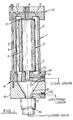
- the illustrated filtration apparatus 1- comprises a cylindrical filter housing 2 with suitably ported end cap assemblies 3 and 4 held together by tie rods 5 (only one shown). Within the housing 2 is an elongate annular filter element 6 (to be described below) defining an annular region between its outer surface and the inner wall of the housing 2.
- Filter element 6 comprises an annular cylindrical porous former 8 (e.g. a sintered ceramic or metallic filter cartridge) on the outer surface of which is a sleeve 9 of porous elastomeric material held in position by clips 10 providing a substantially gas-tight joint.
- annular cylindrical porous former 8 e.g. a sintered ceramic or metallic filter cartridge
- Sleeve 9 in its relaxed condition is of lesser length and diameter than the former 8 so that it has to be stretched in two directions (axially and radially) to fit over the former.
- the relaxed dimensions of the sleeve 9 are selected so that, when mounted in position, the sleeve 9 has the required degree of pre-stretch to open the pores in the sleeve 9 by the required amount.
- End cap assembly 3 i.e. that shown at the top of Fig. 1, includes a central port 11 communicating with the interior of filter element 6 and two ports 12 and 13 each communicating with the annular region 7.
- End cap assembly 4 includes an upper plate 14 and lower block 15.
- Plate 14 is generally annular but has a radially extending spur portion 16 in which is a right angled port 17 providing communication between inside of filter element and the exterior of the apparatus.
- Block 15 includes a downwardly converging frusto-conical bore 18 acting as a hopper.
- a ball valve arrangement 19 is provided at the base of block 15 which also includes a port 20 communicating with the bore 18 through a narrow line 21.
- Fig. 2 diagrammatically illustrates a complete filtration system incorporating the filtration apparatus 1 shown in Fig. 1.
- material to be filtered is supplied by means of a pump 22 from a store 23 to the port 12.
- a gas supply source 24 e.g. a compressor or air cylinder
- ports 11 and 13 are connected for selective communication with ports 11 and 13 by means of respective valves 25 and 26.
- Ports 17 and 20 are associated with respective valves 27 and 28, the function of which will be described below.
- valve 27 To commence filtration, all valves shown in Fig. 2, with the exception of valve 27, are closed and material to be filtered is supplied by the pump 22 through the port 12 into the annular region 7 of the filter housing.
- Filtration takes place by virtue of liquid passing through both the porous elastomeric sleeve 9 and the porous former 8 into the central region of filter element 6 and thence through open valve 27 to a suitable store. Filtered solid is collected on the outer surface of sleeve 8.
- valve 27 is closed.
- Valve 26 is then opened to admit gas at a suitable pressure into annular region 7.
- valve 28 is opened to allow. unfiltered material collected in hopper 18 to be blown through port 20 for return to the store 23.
- Valve 28 is next closed and valve 27 re-opened to allow air to pass through the collected solids for drying purposes. During this stage sufficient pressure may be built up in annular region 7 to prevent slump of the filtered solid. After drying, valves 27 and 28 are closed.
- Valve 25 may now be opened and the build up of gas pressure within filter element 6 will inflate the elastomeric sleeve 9 to a configuration such as that indicated by chain dot line in Fig. 1. This expansion of sleeve 8 will cause break-up of the collected solids which will fall and collect in hopper 18 for subsequent removal through ball valve 19. Additionally, solids trapped in the pores of sleeve 8 will be blown free, as described above. If desired a plusating gas pressure may be applied through part 11 to the interior of filter element 6. This will cause the sleeve 8 to "flutter" and will result in a more efficient discharge of trapped solids. Whichever method is used, removal of the solids from sleeve 8 will be practically complete so that, once sleeve 8 has been deflated, filtration may recommence.
- ball valve 19 may be replaced by a sliding gate valve.
- port 11 may also communicate with a water line for backwashing purposes should this be desired. It is also possible to effect filtration whilst there is at least partial inflation of sleeve 9, to use a different pore size for filtration than would be the case without inflation of the sleeve.
- the inflated sleeve can be further inflated to remove solids as described previously.
Landscapes
- Chemical & Material Sciences (AREA)
- Chemical Kinetics & Catalysis (AREA)
- Filtering Materials (AREA)
- Filtration Of Liquid (AREA)
- Separation Using Semi-Permeable Membranes (AREA)
Applications Claiming Priority (2)
| Application Number | Priority Date | Filing Date | Title |
|---|---|---|---|
| GB8120725 | 1981-07-04 | ||
| GB8120725 | 1981-07-04 |
Publications (2)
| Publication Number | Publication Date |
|---|---|
| EP0069528A2 true EP0069528A2 (fr) | 1983-01-12 |
| EP0069528A3 EP0069528A3 (fr) | 1985-01-09 |
Family
ID=10523024
Family Applications (1)
| Application Number | Title | Priority Date | Filing Date |
|---|---|---|---|
| EP82303400A Withdrawn EP0069528A3 (fr) | 1981-07-04 | 1982-06-29 | Procédé et appareil de filtration |
Country Status (3)
| Country | Link |
|---|---|
| EP (1) | EP0069528A3 (fr) |
| JP (1) | JPS5849414A (fr) |
| CA (1) | CA1187817A (fr) |
Cited By (6)
| Publication number | Priority date | Publication date | Assignee | Title |
|---|---|---|---|---|
| WO1992000798A1 (fr) * | 1990-07-13 | 1992-01-23 | Lanmark Consultants Limited | Ameliorations relatives a la regulation d'ecoulement |
| WO1996028828A1 (fr) * | 1995-03-10 | 1996-09-19 | Vattenfall Ab (Publ) | Procede et appareil pour manipuler des dechets radioactifs |
| US6077425A (en) * | 1995-05-22 | 2000-06-20 | Siemens Aktiengesellschaft | Method of separating a medium into a solids-containing component and a liquid component |
| CN1089612C (zh) * | 1998-07-01 | 2002-08-28 | 周新村 | 强化玻璃的破坏工具 |
| CN110772870A (zh) * | 2019-11-19 | 2020-02-11 | 霍栋 | 一种污水微滤机的滤网自动更换装置 |
| CN115245699A (zh) * | 2021-04-26 | 2022-10-28 | 宝武碳业科技股份有限公司 | 一种沥青过滤器及沥青在线排渣方法 |
Family Cites Families (7)
| Publication number | Priority date | Publication date | Assignee | Title |
|---|---|---|---|---|
| FR445617A (fr) * | 1912-07-01 | 1912-11-15 | James Millar Neil | Appareil de filtrage |
| US2027681A (en) * | 1932-04-20 | 1936-01-14 | Blomfield Engineering Company | Filter |
| FR1594785A (fr) * | 1968-11-04 | 1970-06-08 | ||
| FR2031710A5 (fr) * | 1969-02-04 | 1970-11-20 | Comptoir Filtration Cofi | |
| CH511629A (fr) * | 1969-03-27 | 1971-08-31 | Brasco Sa | Appareil de filtration d'un fluide sous pression |
| US3598242A (en) * | 1969-12-19 | 1971-08-10 | Lambert H Mott | Multiple element filter for polymers |
| DE2308987A1 (de) * | 1973-02-23 | 1974-08-29 | Jessel Co Ltd | Filterkerze |
-
1982
- 1982-06-29 EP EP82303400A patent/EP0069528A3/fr not_active Withdrawn
- 1982-06-30 CA CA000406345A patent/CA1187817A/fr not_active Expired
- 1982-07-05 JP JP57115620A patent/JPS5849414A/ja active Pending
Cited By (7)
| Publication number | Priority date | Publication date | Assignee | Title |
|---|---|---|---|---|
| WO1992000798A1 (fr) * | 1990-07-13 | 1992-01-23 | Lanmark Consultants Limited | Ameliorations relatives a la regulation d'ecoulement |
| WO1996028828A1 (fr) * | 1995-03-10 | 1996-09-19 | Vattenfall Ab (Publ) | Procede et appareil pour manipuler des dechets radioactifs |
| US6077425A (en) * | 1995-05-22 | 2000-06-20 | Siemens Aktiengesellschaft | Method of separating a medium into a solids-containing component and a liquid component |
| CN1089612C (zh) * | 1998-07-01 | 2002-08-28 | 周新村 | 强化玻璃的破坏工具 |
| CN110772870A (zh) * | 2019-11-19 | 2020-02-11 | 霍栋 | 一种污水微滤机的滤网自动更换装置 |
| CN115245699A (zh) * | 2021-04-26 | 2022-10-28 | 宝武碳业科技股份有限公司 | 一种沥青过滤器及沥青在线排渣方法 |
| CN115245699B (zh) * | 2021-04-26 | 2023-11-17 | 宝武碳业科技股份有限公司 | 一种沥青过滤器及沥青在线排渣方法 |
Also Published As
| Publication number | Publication date |
|---|---|
| CA1187817A (fr) | 1985-05-28 |
| EP0069528A3 (fr) | 1985-01-09 |
| JPS5849414A (ja) | 1983-03-23 |
Similar Documents
| Publication | Publication Date | Title |
|---|---|---|
| US1642864A (en) | Filter | |
| DE4325660C2 (de) | Verfahren und Vorrichtung zum Reinigen eines Gasfiltrationssystems und deren Verwendung | |
| JP2514997B2 (ja) | 媒体の濾過方法およびそれに用いる装置 | |
| US5207930A (en) | Filtration system with helical filter cartridge | |
| US4196027A (en) | Method of making filter elements for gas or liquid | |
| JPS592530B2 (ja) | 逆洗式濾過装置 | |
| DE2260461B2 (de) | Filterzentrifuge | |
| DE2614336A1 (de) | Rohrfoermiges filterelement und verfahren zu seiner herstellung | |
| DE10154549A1 (de) | Vorrichtung zum Trennen von Stoffen | |
| US4560483A (en) | Process and apparatus for filtration of oil and gas well fluids | |
| EP0555740A1 (fr) | Installation de filtrage | |
| EP0069528A2 (fr) | Procédé et appareil de filtration | |
| US3421630A (en) | Filter element and filter system | |
| US3155613A (en) | Filtering apparatus | |
| JPH0217925A (ja) | 中空糸膜濾過装置の逆洗方法 | |
| US3399778A (en) | Filter apparatus having tubular filter medium | |
| US2720314A (en) | Filter with air bump backwash means | |
| US4622144A (en) | Pressure filter apparatus | |
| US12589340B2 (en) | Rotary filter and associated filtering method | |
| US1823171A (en) | Filtration | |
| JP2507589B2 (ja) | ろ過装置 | |
| US4159247A (en) | Locking filter apparatus and method | |
| EP0204871A1 (fr) | Procédé et appareil pour la filtration de fluides provenant du forage d'huile ou de gaz | |
| EP0645446B1 (fr) | Dispositif pour recueillir les agents stabilisant des boissons ou d'autres liquides | |
| EP0594567B1 (fr) | Tamis |
Legal Events
| Date | Code | Title | Description |
|---|---|---|---|
| PUAI | Public reference made under article 153(3) epc to a published international application that has entered the european phase |
Free format text: ORIGINAL CODE: 0009012 |
|
| AK | Designated contracting states |
Designated state(s): AT BE CH DE FR GB IT LI LU NL SE |
|
| PUAL | Search report despatched |
Free format text: ORIGINAL CODE: 0009013 |
|
| AK | Designated contracting states |
Designated state(s): AT BE CH DE FR GB IT LI LU NL SE |
|
| 17P | Request for examination filed |
Effective date: 19850627 |
|
| 17Q | First examination report despatched |
Effective date: 19860128 |
|
| R17C | First examination report despatched (corrected) |
Effective date: 19870209 |
|
| STAA | Information on the status of an ep patent application or granted ep patent |
Free format text: STATUS: THE APPLICATION IS DEEMED TO BE WITHDRAWN |
|
| 18D | Application deemed to be withdrawn |
Effective date: 19881231 |
|
| RIN1 | Information on inventor provided before grant (corrected) |
Inventor name: ALLISON, WILLIAM |