EP0069530A2 - Bohrschlammumleitungssteuervorrichtung zum Messen in einem Bohrloch während des Bohrens - Google Patents
Bohrschlammumleitungssteuervorrichtung zum Messen in einem Bohrloch während des Bohrens Download PDFInfo
- Publication number
- EP0069530A2 EP0069530A2 EP82303418A EP82303418A EP0069530A2 EP 0069530 A2 EP0069530 A2 EP 0069530A2 EP 82303418 A EP82303418 A EP 82303418A EP 82303418 A EP82303418 A EP 82303418A EP 0069530 A2 EP0069530 A2 EP 0069530A2
- Authority
- EP
- European Patent Office
- Prior art keywords
- valve
- fluid
- pressure
- turbine
- drilling
- Prior art date
- Legal status (The legal status is an assumption and is not a legal conclusion. Google has not performed a legal analysis and makes no representation as to the accuracy of the status listed.)
- Withdrawn
Links
Images

Classifications
-
- E—FIXED CONSTRUCTIONS
- E21—EARTH OR ROCK DRILLING; MINING
- E21B—EARTH OR ROCK DRILLING; OBTAINING OIL, GAS, WATER, SOLUBLE OR MELTABLE MATERIALS OR A SLURRY OF MINERALS FROM WELLS
- E21B41/00—Equipment or details not covered by groups E21B15/00 - E21B40/00
- E21B41/0085—Adaptations of electric power generating means for use in boreholes
-
- E—FIXED CONSTRUCTIONS
- E21—EARTH OR ROCK DRILLING; MINING
- E21B—EARTH OR ROCK DRILLING; OBTAINING OIL, GAS, WATER, SOLUBLE OR MELTABLE MATERIALS OR A SLURRY OF MINERALS FROM WELLS
- E21B4/00—Drives for drilling, used in the borehole
- E21B4/02—Fluid rotary type drives
-
- E—FIXED CONSTRUCTIONS
- E21—EARTH OR ROCK DRILLING; MINING
- E21B—EARTH OR ROCK DRILLING; OBTAINING OIL, GAS, WATER, SOLUBLE OR MELTABLE MATERIALS OR A SLURRY OF MINERALS FROM WELLS
- E21B47/00—Survey of boreholes or wells
- E21B47/12—Means for transmitting measuring-signals or control signals from the well to the surface, or from the surface to the well, e.g. for logging while drilling
- E21B47/14—Means for transmitting measuring-signals or control signals from the well to the surface, or from the surface to the well, e.g. for logging while drilling using acoustic waves
- E21B47/18—Means for transmitting measuring-signals or control signals from the well to the surface, or from the surface to the well, e.g. for logging while drilling using acoustic waves through the well fluid, e.g. mud pressure pulse telemetry
-
- F—MECHANICAL ENGINEERING; LIGHTING; HEATING; WEAPONS; BLASTING
- F03—MACHINES OR ENGINES FOR LIQUIDS; WIND, SPRING, OR WEIGHT MOTORS; PRODUCING MECHANICAL POWER OR A REACTIVE PROPULSIVE THRUST, NOT OTHERWISE PROVIDED FOR
- F03B—MACHINES OR ENGINES FOR LIQUIDS
- F03B13/00—Adaptations of machines or engines for special use; Combinations of machines or engines with driving or driven apparatus; Power stations or aggregates
- F03B13/02—Adaptations for drilling wells
Definitions
- This invention relates to a by-pass device for use in controlling the pressure differential across a drilling fluid operated power generator located in a drill string.
- the downhole equipment may require electrical power which may be provided by a power supply that includes a motive power source to extract mechanical energy from kinetic energy of drilling fluid passing through the drill string, and an electrical power source in the form of a generator or an alternator coupled with the motive power source.
- a power supply that includes a motive power source to extract mechanical energy from kinetic energy of drilling fluid passing through the drill string, and an electrical power source in the form of a generator or an alternator coupled with the motive power source.
- a power supply that includes a motive power source to extract mechanical energy from kinetic energy of drilling fluid passing through the drill string, and an electrical power source in the form of a generator or an alternator coupled with the motive power source.
- Regulating the operation of this power supply requires the consideration of several factors including electrical loading of the electrical power source due to operating demands of the associated electrical system; pressure and flow rate variations in the drilling fluid flow, and occluding, plugging or clogging of the motive power source with particulate matter that is carried in the drilling fluid.
- the present invention concerns the flow of drilling fluid through the motive power source portion of this apparatus.
- the motive power source includes a turbine with its blade or rotary element mounted on or operably connected to the rotatable shaft of an alternator.
- the turbine receives high pressure drilling fluid at its inlet and discharges the fluid at a lower pressure at its outlet.
- the turbine is designed so that motion of a valve member relative to the inlet will regulate the quantity of drilling fluid passing through the turbine in relation to the quantity of drilling fluid by-passing the turbine's inlet.
- a movable valve member in another prior construction of this equipment a movable valve member can be provided which is spring urged to a position that directs substantially all of the drilling fluid to pass through the turbine and relaxed from this position only in response to the drilling fluid pressure acting in opposition to the spring.
- This arrangement while providing some degree of regulation for fluid flow through the turbine is not responsive to rapid changes of the differential across the turbine. Also, it is not responsive to short duration pressure pulses in the mud flow that tend to change the speed of the turbine.
- the present invention characterised in that the by-pass device comprises a valve in the drill string mounted up stream of the power generator and operable to control fluid flow past the generator; a valve actuator operable to displace the valve in variable relation between first and second positions; and a valve actuator control operable to control the valve actuator in order to move the valve and thereby maintain a fluid pressure differential across the generator within a predetermined range.
- the invention provides a mud by-pass regulator apparatus for a measurement while drilling system having a valve, a valve actuator and a valve actuator control that function cooperatively to regulate the flow of mud or drilling fluid passing through the inlet and by-passing a turbine in a downhole power supply wherein such apparatus overcomes the aforementioned disadvantages of the prior art devices.
- generator means a device or devices for extracting power from drilling mud for some purpose.
- the generator of the preferred embodiment is an electrical power generator and comprises a turbine coupled to an alternator. Other arrangements are. however, possible.
- Fig. 1 this illustrates a measurement while drilling system incorporated with an earth borehole drilling rig indicated generally at 10.
- the measurement while drilling system includes a downhole apparatus at the bottom portion of drill string 12 to sense various parameters and transmit such to the earth's surface through pressure pulses in the drilling fluid or mud flow.
- the system has equipment including electronic circuitry and display for recovering this data and displaying it for observation and also for recording purposes.
- Drilling fluid or mud under pressure is moved by pump 14 through drill string 12 to the bottom of borehole 16 where it exits at drilling bit 18.
- the mud flows through the by-pass regulator 20 and around a portion of power supply 22 where kinetic energy is extracted from the flowing fluid by a motive power source and transformed into electrical energy for use in operating other portions of the downhole apparatus.
- the downhole portion of this apparatus can include mechanical and geometric sensors 24, lithological sensors 26, and a transmitter 28 along with associated data preparation circuitry.
- this downhole portion of the apparatus In operation of this downhole portion of the apparatus it can function cyclically to sample the data and transmit it to the earth's surface.
- demands for electrical power may vary depending upon the cyclic state of the electrical apparatus.
- electrical power demands may generally be below some determinable value and it is this value which forms a minimum power output requirement for the power supply.
- a requirement of the power supply of the apparatus described herein is to ideally be a constant output power supply so that electrical requirements of the system are met.
- the mud pressure can be varied depending upon the speed of pump 14 and other factors.
- the drilling mud pressure is normally varied depending upon the drilling conditions at the well and the desire of the drilling operators. Thus, it can vary from a minimum of about 3.445 MPa to a maximum in the neighborhood of 137.
- Ihis mud pressure will also vary in magnitude due to pulsations from the mud pump at the earth's surface and also because of the short duration pressure pulses used for data transmission from the downhole equipment to the earth's surface data receiving equipment.
- the by-pass regulator 20 is contained within a special collar 30 that is coupled into drill string 12 between the lower most joint of conventional drill pipe and drilling bit 18.
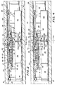
- the left hand portion of Fig. 2 is the upper end of the apparatus when it is positioned for operation in a well.
- Collar 30 receives the drilling fluid or mud through the interior thereof just as do the conventional joints of drill pipe.
- the interior of collar 30 is specifically adapted for mounting the measurement while drilling apparatus.
- Collar 30 has a cross sectionally circular interior surface 32 extending through the portion shown in Fig. 2.
- By-pass regulator 20 is mounted at the upper end portion of this downhole apparatus as illustrated generally in Fig. 1 so that.drilling fluid will pass through this portion of the apparatus prior to passing around other lower portions of the downhole equipment.
- a by-pass housing inlet sleeve 34 at the upper portion of by-pass regulator 20 receives the mud flow and forms the upper end portion of the device.
- a seal ring 36 mounted in a groove around the exterior of by-pass housing inlet sleeve 34 seals between by-pass housing inlet sleeve 34 and collar interior surface 32 thereby preventing mud flow around by-pass regulator 20.
- alternator housing 40 Threadedly attached to by-pass housing sleeve 38 and extending downwardly therefrom is alternator housing 40.
- Alternator housing 40 is mounted in a spaced relation around the exterior of alternator 42.
- Alternator housing 40 is secured to alternator 42 by a plurality of mounting blocks 44 on alternator 42. These mounting blocks 44 are secured in a spaced relation around the exterior of alternator 42.
- the lower end portion of alternator housing 40 is provided with a plurality of alternately spaced passageways and mounting lugs 45. Aligning mounting blocks 44 and lugs 45 positions the passageways so that the drilling fluid or mud can flow from the turbine 88 through the interior of alternator housing 40 into the annular space between alternator 42 and collar interior surface 32 when exiting the by-pass regulator.
- housing inlet sleeve 34 At the upper portion of by-pass regulator 20 housing inlet sleeve 34 a recess 46 is formed around the interior thereof for use in removal of the sleeve from collar 30.
- By-pass housing inlet sleeve 34 has a reduced diameter interior passageway 48 through a mid-portion thereof which serves as the fluid passageway and as a support for the upper end portion of by-pass sleeve 50.
- a seal ring 52 is mounted in a circular groove around the interior passageway 48 of by-pass housing inlet sleeve 34 to seal against an exterior portion of by-pass sleeve 50.
- the exterior of the lower portion of by-pass housing inlet sleeve 34 is threaded to receive the interior of by-pass housing sleeve 38 therearound.
- Seal rings 47 and 51 are respectively mounted in grooves in sleeves 34 and 38 to provide a fluid seal between these members.
- the lower portion of the interior of by-pass housing inlet sleeve 34 has a recess to support and contain spring 58 that extends between a downwardly facing abutment on by-pass housing inlet sleeve 34 and an upwardly facing abutment on by-pass sleeve 50.
- By-pass sleeve 50 has an interior passageway 49 therethrough to pass drilling mud to a turbine that is described hereinafter.
- By-pass sleeve 50 divides by-pass regulator 20 into a high pressure portion and a low pressure portion at an outwardly extending radial enlargement 60.
- This radial enlargement 60 will be referred to hereinafter as a piston portion of the by-pass sleeve.
- Piston portion 60 is provided with a seal ring 62 therearound to seal on an interior surface of by-pass housing sleeve 38.
- a low pressure fluid chamber 64 is formed between by-pass housing inlet sleeve 34, by-pass sleeve 50, and by-pass housing sleeve 38. Low pressure fluid chamber 64 is in fluid communication with collar interior annulus by low pressure port 66.
- Collar interior annulus 68 is the annular opening or space around the equipment contained in special collar 30. During operation the fluid pressure in this annulus is lower than the mud pressure above by-pass regulator 20 and it is greater than the borehole annulus fluid pressure.
- Low pressure port 66 joins a longitudinally oriented slot 70 extending from port 66 to the lower end of the larger diameter segment of by-pass housing sleeve 38. A plurality of such ports and slots like port 66 and slot 70 are provided in spaced relation around the periphery of by- pass housing sleeve 38. This low pressure fluid connection enables fluid at a low pressure to act on the upper portion of piston 60 in conjunction with spring 58 to urge by-pass sleeve 50 in the downward direction or toward the first position of the valve.
- a high pressure chamber 72 is formed between the exterior of by-pass sleeve 50 and an interior portion of by-pass housing sleeve 38.
- High pressure chamber 72 extends between seal ring 62 around piston portion 60 to another seal ring 74 mounted in a groove in the interior of the lower portion of by-pass housing sleeve 38 and contacting an exterior seal surface 76 on by-pass sleeve 50.
- a high pressure port 78 through by- pass sleeve 50 communicates high pressure drilling fluid or mud from the interior of by-pass sleeve 50 to high pressure chamber 72 in order to apply this type fluid pressure to the lower side of piston portion 60.
- a spacer ring 80 is positioned adjacent to the lower side of piston portion 60 and contactable with an upwardly facing abutment around the interior of by-pass housing sleeve 38.
- Spacer ring 80 provides a physical separation between piston portion 60 and a facing portion of by-pass housing sleeve 38 in order to prevent the accumulation of foreign material between these portions of the respective parts.
- Spacer ring 80 fits snugly into by-pass housing sleeve 38 where it is retained in by-pass housing sleeve 38.
- Spacer ring 80 has a plurality of spaced apart lugs 81 thereon that will contact the downwardly facing side of piston portion 60 when in the position shown in Fig. 2.
- Spacer ring 80 can remain in place in by-pass housing sleeve 38 as by-pass sleeve 50 moves upward as is illustrated in Fig. 4.
- the interior of spacer ring 80 has its interior diameter surface 83 substantially separated from the exterior of by-pass housing sleeve 38.
- the opening between spacer ring 80 and by-pass housing sleeve 38 combined with the space between lugs 81 permits fluid pressure in high pressure fluid chamber 72 to act over the entire downwardly facing side of piston portion 60 when it is positioned as shown in Fig. 2.
- Alternator housing 40 is a cylindrical member that on its upper end portion is threadedly mounted with the exterior of the lower portion of by-pass housing sleeve 38. The upper end of alternator housing 40 is spaced from the lower end of the largest diameter portion of by-pass housing sleeve 38.
- a plurality of longitudinal slots are provided in alternator housing 40 from its upper end portion to a mid-portion thereof below its threaded mounting with by-pass housing sleeve 38.
- Slots 82 provide for low pressure fluid communication between the annular space 86 within alternator housing 40 around turbine's blade 88 and other low pressure fluid in collar interior annulus 68.
- Annular space 86 is in fluid communication with collar interior and annulus 68 through slots 82 and through openings in alternator housing 40 between mounting blocks 44.
- the turbine has its rotary element or blade 88 mounted on the rotatable shaft of alternator 42.
- Turbine blade 88 is of the reaction type design which reacts to the exit velocity of drilling fluid.
- Turbine blade 88 is provided with an upwardly facing inlet having a pair of openings 90 to receive mud or drilling fluid through the interior of by-pass sleeve 50 as can be seen in Figs. 2 and 5.
- Turbine blade 88 has outlet "D" shaped openings 92 on its peripheral exterior as shown in Fig. 4. Outlets 92 discharge the mud into annular space 86 in alternator housing 40.
- valve assembly At the lower end of by-pass sleeve 50 is the valve assembly that has a ring like resilient valve element 94 mounted therearound.
- Valve element 94 has a diameter sized corresponding to that of the upwardly facing portion of turbine blade 88.
- the facing end surfaces of valve element 94 and turbine blade's inlet side are spaced apart a small distance as shown in Fig. 2 when the valve is in its first or most restrictive position so that fluid flow into and through turbine blade inlet 90 is maximized and fluid flow around turbine blade 88 between its inlets and the outlets is minimized.
- the by-pass regulator 20 of this invention In operation of the by-pass regulator 20 of this invention it will initially have the valve essentially closed or in the first position as shown in Fig. 2 before the mud is pumped through the tubing string.
- Drilling mud flows through the interior of tubine string 12 including the interior of collar 30 and the interior of by-pass sleeve 50, through turbine blade 88 and into collar interior annulus 68 whereupon it flows in a condinued downward direction around other portions of the measurement while drilling apparatus and exits at drill bit 18 into the borehole annulus.
- This drilling fluid is pumped downward at a pressure that can be as high as about 3445 MPa when measured at the earth's surface which will be a greater pressure at the by-pass regulator 20 depending upon the depth of the well and the weight of the drilling fluid involved.
- the flow rate of drilling mud through the drill string of an operating drill rig will vary depending upon the pump capacity of the rig, depth of the well and physical properties of the drilling mud just to mention a few variables. This flow rate can be maintained within certain limits in order to provide a typical or average drilling mud flow rate. In wells of depths between about 762 m to about 6095 m it is possible to maintain the drilling mud flow rate between about 1135 to 4542 litres per minute with an average flow rate of about 2650 litres per minute. With by-pass regulator 20 in the position shown in Fig. 2 the maximum amount of mud is directed into turbine blade inlet openings 90 so that turbine blade 88 will receive the maximum amount of fluid. This operating condition will permit the turbine to receive the maximum amount of fluid. This operating condition will permit the turbine to extract a maximum amount of kinetic energy from the flowing drilling fluid.
- valve element 94 and turbine blade 88 can be ajusted by the threaded connection between alternator housing 40 and by-pass housing sleeve 38. When a desired spacing dimension is achieved these two housings are secured in a fixed rotational position by set screws 84. Adjustment of this spacing dimension functions to adjust the minimum fluid by-pass flow rate of by-pass regulator 20. It also has an effect on the average flow rate setting and the maximum flow rate by-pass operation. Adjustment of this factor presets by-pass regulator 20 for a range of drilling mud flow rates that are to be expected prior to using the equipment. This adjustment can be done from the exterior of this apparatus prior to placing it inside collar 30 by loosening set screws 84 and rotating the separate portions of the housing in order to set the spacing for a particular average flow rate to be encountered on a specific drilling rig.
- By-pass regulator 20 is designed to maintain a predetermined pressure drop between mud passageway 49 in by-pass sleeve 50 and annular space 86 surrounding the outlet portion of turbine blade 88.
- the pressure drop between these two areas is intended to be kept with the range of about 344 kPa to about 3440 kPa in a broad selection. Also this pressure range can be kept between 1033 to 1378 kPa in a narrow selection of this range.
- the by-pass regulator is also designed to react quickly to changes that effect the pressure drop across turbine blade 88 so that small and short duration pulsations in the mud pressure will be compensated for by this apparatus. In an overall persepctive these features of by-pass regulator 20 function to operate the turbine at a substantially constant energy output condition so that the associated electrical power supply of the measurement while drilling apparatus also has a substantially constant power output.
- valve actuator control is established to move the valve actuator including valve member 94 toward turbine blade 88.
- the amount of fluid available at the inlets of turbine blade 88 is increased from its previous operating condition and as a result it can be expected that the rotational speed of the turbine may also be slightly increased in order that the amount of energy extracted from the mud flow by the turbine will remain appreciably constant as desired.
- spring 58 is illustrated as a helical spring however it is to be understood that the spring can be provided in another configuration such as a mechanical spring of a different configuration, or an elastomeric spring, or a combination of elastomeric and mechanical springs or a fluid spring.
- the valve member is shown as a ring-like member however it can be reconfigured to other physical arrangements depending upon the particular turbine blade construction.
- by-pass sleeve 50 is shown as an elongated member having a piston portion 60 extending radially outward around a mid-portion thereof however it is to be understood that this can be physically reconfigured to conform with other physical constraints of a particular measurement while drilling apparatus.
Landscapes
- Engineering & Computer Science (AREA)
- Life Sciences & Earth Sciences (AREA)
- Geology (AREA)
- Mining & Mineral Resources (AREA)
- Physics & Mathematics (AREA)
- Environmental & Geological Engineering (AREA)
- Fluid Mechanics (AREA)
- General Life Sciences & Earth Sciences (AREA)
- Geochemistry & Mineralogy (AREA)
- Mechanical Engineering (AREA)
- Combustion & Propulsion (AREA)
- Chemical & Material Sciences (AREA)
- General Engineering & Computer Science (AREA)
- Acoustics & Sound (AREA)
- Remote Sensing (AREA)
- Geophysics (AREA)
- Earth Drilling (AREA)
- Nozzles For Spraying Of Liquid Fuel (AREA)
- Measuring Fluid Pressure (AREA)
- Activated Sludge Processes (AREA)
- Length Measuring Devices Characterised By Use Of Acoustic Means (AREA)
- Treatment Of Sludge (AREA)
- Other Liquid Machine Or Engine Such As Wave Power Use (AREA)
Applications Claiming Priority (2)
| Application Number | Priority Date | Filing Date | Title |
|---|---|---|---|
| US280433 | 1981-07-06 | ||
| US06/280,433 US4396071A (en) | 1981-07-06 | 1981-07-06 | Mud by-pass regulator apparatus for measurement while drilling system |
Publications (2)
| Publication Number | Publication Date |
|---|---|
| EP0069530A2 true EP0069530A2 (de) | 1983-01-12 |
| EP0069530A3 EP0069530A3 (de) | 1985-07-31 |
Family
ID=23073068
Family Applications (1)
| Application Number | Title | Priority Date | Filing Date |
|---|---|---|---|
| EP82303418A Withdrawn EP0069530A3 (de) | 1981-07-06 | 1982-06-29 | Bohrschlammumleitungssteuervorrichtung zum Messen in einem Bohrloch während des Bohrens |
Country Status (5)
| Country | Link |
|---|---|
| US (1) | US4396071A (de) |
| EP (1) | EP0069530A3 (de) |
| JP (1) | JPS5817992A (de) |
| CA (1) | CA1175413A (de) |
| NO (1) | NO822340L (de) |
Cited By (14)
| Publication number | Priority date | Publication date | Assignee | Title |
|---|---|---|---|---|
| FR2545534A1 (fr) * | 1983-05-06 | 1984-11-09 | Baker Oil Tools Inc | Appareil de transmission et d'indication de couple en fond de sondage |
| WO1998005848A3 (en) * | 1996-08-01 | 1998-06-25 | Camco Int | Method and apparatus for the downhole metering and control of fluids produced from wells |
| US5961841A (en) * | 1996-12-19 | 1999-10-05 | Camco International Inc. | Downhole fluid separation system |
| US6148843A (en) * | 1996-08-15 | 2000-11-21 | Camco International Inc. | Variable orifice gas lift valve for high flow rates with detachable power source and method of using |
| US7322433B2 (en) | 2003-07-09 | 2008-01-29 | Shell Oil Company | Tool for excavating an object |
| US7419014B2 (en) | 2003-10-29 | 2008-09-02 | Shell Oil Company | Fluid jet drilling tool |
| US7448151B2 (en) | 2003-07-09 | 2008-11-11 | Shell Oil Company | Tool for excavating an object |
| US7493966B2 (en) | 2003-07-09 | 2009-02-24 | Shell Oil Company | System and method for drilling using a modulated jet stream |
| GB2453867A (en) * | 2007-10-17 | 2009-04-22 | Weatherford Energy Services Gmbh | A turbine for power generation in a drill string |
| DE102007050048A1 (de) | 2007-10-17 | 2009-04-23 | Weatherford Energy Services Gmbh | Turbine zur Energieerzeugung in einem Bohrstrang |
| US7757781B2 (en) | 2007-10-12 | 2010-07-20 | Halliburton Energy Services, Inc. | Downhole motor assembly and method for torque regulation |
| GB2467046A (en) * | 2009-01-16 | 2010-07-21 | Weatherford Energy Services Gm | Drill string turbine for driving a generator |
| CN102345449A (zh) * | 2011-08-31 | 2012-02-08 | 中国海洋石油总公司 | 发电机流量试验测试固定短节 |
| US9932772B2 (en) | 2011-09-20 | 2018-04-03 | Halliburton Energy Services, Inc. | Systems and methods for limiting torque transmission |
Families Citing this family (39)
| Publication number | Priority date | Publication date | Assignee | Title |
|---|---|---|---|---|
| JPS6195989A (ja) * | 1984-10-18 | 1986-05-14 | Dainippon Printing Co Ltd | 感熱転写シ−ト |
| JPS6186288A (ja) * | 1984-10-05 | 1986-05-01 | Dainippon Printing Co Ltd | 感熱転写シ−ト |
| US4914591A (en) * | 1988-03-25 | 1990-04-03 | Amoco Corporation | Method of determining rock compressive strength |
| US5184692A (en) * | 1991-03-18 | 1993-02-09 | Schlumberger Technology Corporation | Retrievable radiation source carrier |
| US5679894A (en) * | 1993-05-12 | 1997-10-21 | Baker Hughes Incorporated | Apparatus and method for drilling boreholes |
| WO1998016712A1 (en) * | 1996-10-11 | 1998-04-23 | Baker Hughes Incorporated | Apparatus and method for drilling boreholes |
| US6191561B1 (en) | 1998-01-16 | 2001-02-20 | Dresser Industries, Inc. | Variable output rotary power generator |
| US6607030B2 (en) * | 1998-12-15 | 2003-08-19 | Reuter-Stokes, Inc. | Fluid-driven alternator having an internal impeller |
| US6672409B1 (en) | 2000-10-24 | 2004-01-06 | The Charles Machine Works, Inc. | Downhole generator for horizontal directional drilling |
| US9051781B2 (en) | 2009-08-13 | 2015-06-09 | Smart Drilling And Completion, Inc. | Mud motor assembly |
| US9745799B2 (en) | 2001-08-19 | 2017-08-29 | Smart Drilling And Completion, Inc. | Mud motor assembly |
| US7086486B2 (en) * | 2004-02-05 | 2006-08-08 | Bj Services Company | Flow control valve and method of controlling rotation in a downhole tool |
| US7921937B2 (en) * | 2007-01-08 | 2011-04-12 | Baker Hughes Incorporated | Drilling components and systems to dynamically control drilling dysfunctions and methods of drilling a well with same |
| US8151905B2 (en) * | 2008-05-19 | 2012-04-10 | Hs International, L.L.C. | Downhole telemetry system and method |
| US9598920B2 (en) | 2011-09-09 | 2017-03-21 | Baker Hughes Incorporated | Drilling apparatus including a fluid bypass device and methods of using same |
| US9103180B2 (en) | 2011-09-09 | 2015-08-11 | Baker Hughes Incorporated | Drilling apparatus including a fluid bypass device and methods of using same |
| US9674063B2 (en) * | 2011-09-28 | 2017-06-06 | Hewlett-Packard Development Company, L.P. | Managing data usage of a computing device |
| US9404326B2 (en) | 2012-04-13 | 2016-08-02 | Saudi Arabian Oil Company | Downhole tool for use in a drill string |
| EP2743445A1 (de) * | 2012-12-11 | 2014-06-18 | Welltec A/S | Stromversorgungssystem für Bohrloch |
| US9228402B2 (en) | 2013-10-04 | 2016-01-05 | Bico Drilling Tools, Inc. | Anti-stall bypass system for downhole motor |
| US9982511B2 (en) | 2014-01-03 | 2018-05-29 | Proserv Operations, Inc. | Dirty fluid pressure regulator and control valve |
| US10508538B2 (en) | 2014-12-01 | 2019-12-17 | Evolution Engineering Inc. | Fluid pressure pulse generator for a downhole telemetry tool |
| US10670155B2 (en) | 2015-10-05 | 2020-06-02 | Proserv Gilmore Valve Llc | Latching poppet valve |
| US10487951B2 (en) | 2016-01-22 | 2019-11-26 | Proserv Operations, Inc. | Non-interflow directional control valve |
| US10591076B2 (en) | 2016-09-15 | 2020-03-17 | Proserv Operations, Inc. | Low friction hydraulic circuit control components |
| US10590709B2 (en) | 2017-07-18 | 2020-03-17 | Reme Technologies Llc | Downhole oscillation apparatus |
| US11248418B2 (en) | 2017-08-07 | 2022-02-15 | BICO Drilling Tools, Inc | Drilling motor interior valve |
| US10739796B2 (en) | 2017-09-22 | 2020-08-11 | Proserv Gilmore Valve Llc | Pressure regulator with reconfigurable hydraulic dampening |
| US10633951B2 (en) | 2017-09-22 | 2020-04-28 | Proserv Operations, Inc. | Pressure regulator with user selectable dampening |
| US11022226B2 (en) | 2018-03-20 | 2021-06-01 | Proserv Operations, Inc. | Microfluidic valve |
| US11054050B2 (en) | 2018-08-13 | 2021-07-06 | Proserv Operations Inc. | Valve with press-fit insert |
| US11209096B2 (en) | 2018-11-19 | 2021-12-28 | Proserv Operations, Inc. | Bilateral and throttling directional control valve |
| US11261982B2 (en) | 2019-06-27 | 2022-03-01 | Proserv Gilmore Valve Llc | Pressure relief valve with bi-directional seat |
| US11828370B2 (en) | 2020-01-02 | 2023-11-28 | Proserv Gilmore Valve Llc | Check valve with conforming seat |
| EP4441405A1 (de) | 2021-12-03 | 2024-10-09 | Proserv Gilmore Valve LLC | Druckentlastungsventil für hochdruckfluide, einschliesslich schleifmittelbeladener fluide |
| CN116398046B (zh) * | 2021-12-27 | 2025-10-03 | 中国石油化工股份有限公司 | 状态自适应的涡轮式脉冲发生器 |
| CN116591882B (zh) * | 2023-05-04 | 2025-12-19 | 中国铁建重工集团股份有限公司 | 一种高落差掘进机用透平电机泵组 |
| CN116905993B (zh) * | 2023-08-29 | 2024-01-30 | 西南石油大学 | 一种可实现多梯度控压钻井的钻井调节装置与方法 |
| CN118686608B (zh) * | 2024-08-29 | 2024-11-05 | 山东省煤田地质局第三勘探队 | 一种井下深度探测装置 |
Family Cites Families (9)
| Publication number | Priority date | Publication date | Assignee | Title |
|---|---|---|---|---|
| US2787759A (en) * | 1950-08-31 | 1957-04-02 | Jan J Arps | Apparatus for logging wells |
| FR1168061A (fr) * | 1956-12-07 | 1958-12-04 | Turbine de forage à enclenchement sélectif | |
| US3194325A (en) * | 1957-07-18 | 1965-07-13 | Jr Sabin J Gianelloni | Fluid control valve for turbodrill |
| US3302457A (en) * | 1964-06-02 | 1967-02-07 | Sun Oil Co | Method and apparatus for telemetering in a bore hole by changing drilling mud pressure |
| US3693428A (en) * | 1970-07-24 | 1972-09-26 | Jean Pierre Le Peuvedic | Hydraulic control device for transmitting measuring values from the bottom of a well to the surface as pressure pulses through the drilling mud |
| FR2145060A5 (de) * | 1971-07-07 | 1973-02-16 | Inst Francais Du Petrole | |
| US3964556A (en) * | 1974-07-10 | 1976-06-22 | Gearhart-Owen Industries, Inc. | Downhole signaling system |
| US4184545A (en) * | 1978-03-27 | 1980-01-22 | Claycomb Jack R | Measuring and transmitting apparatus for use in a drill string |
| US4275795A (en) * | 1979-03-23 | 1981-06-30 | Baker International Corporation | Fluid pressure actuated by-pass and relief valve |
-
1981
- 1981-07-06 US US06/280,433 patent/US4396071A/en not_active Expired - Fee Related
-
1982
- 1982-06-01 CA CA000404259A patent/CA1175413A/en not_active Expired
- 1982-06-29 EP EP82303418A patent/EP0069530A3/de not_active Withdrawn
- 1982-07-05 JP JP57116681A patent/JPS5817992A/ja active Pending
- 1982-07-05 NO NO822340A patent/NO822340L/no unknown
Cited By (22)
| Publication number | Priority date | Publication date | Assignee | Title |
|---|---|---|---|---|
| FR2545534A1 (fr) * | 1983-05-06 | 1984-11-09 | Baker Oil Tools Inc | Appareil de transmission et d'indication de couple en fond de sondage |
| WO1998005848A3 (en) * | 1996-08-01 | 1998-06-25 | Camco Int | Method and apparatus for the downhole metering and control of fluids produced from wells |
| US6000468A (en) * | 1996-08-01 | 1999-12-14 | Camco International Inc. | Method and apparatus for the downhole metering and control of fluids produced from wells |
| US6148843A (en) * | 1996-08-15 | 2000-11-21 | Camco International Inc. | Variable orifice gas lift valve for high flow rates with detachable power source and method of using |
| US5961841A (en) * | 1996-12-19 | 1999-10-05 | Camco International Inc. | Downhole fluid separation system |
| US7322433B2 (en) | 2003-07-09 | 2008-01-29 | Shell Oil Company | Tool for excavating an object |
| US7448151B2 (en) | 2003-07-09 | 2008-11-11 | Shell Oil Company | Tool for excavating an object |
| US7493966B2 (en) | 2003-07-09 | 2009-02-24 | Shell Oil Company | System and method for drilling using a modulated jet stream |
| US7419014B2 (en) | 2003-10-29 | 2008-09-02 | Shell Oil Company | Fluid jet drilling tool |
| US7757781B2 (en) | 2007-10-12 | 2010-07-20 | Halliburton Energy Services, Inc. | Downhole motor assembly and method for torque regulation |
| DE102007050048A1 (de) | 2007-10-17 | 2009-04-23 | Weatherford Energy Services Gmbh | Turbine zur Energieerzeugung in einem Bohrstrang |
| DE102007050048B4 (de) * | 2007-10-17 | 2009-06-18 | Weatherford Energy Services Gmbh | Turbine zur Energieerzeugung in einem Bohrstrang |
| GB2453867A (en) * | 2007-10-17 | 2009-04-22 | Weatherford Energy Services Gmbh | A turbine for power generation in a drill string |
| US8092147B2 (en) | 2007-10-17 | 2012-01-10 | Weatherford Energy Services Gmbh | Turbine for power generation in a drill string |
| GB2453867B (en) * | 2007-10-17 | 2012-02-08 | Weatherford Energy Services Gmbh | Turbine for power generation in a drill string |
| GB2467046A (en) * | 2009-01-16 | 2010-07-21 | Weatherford Energy Services Gm | Drill string turbine for driving a generator |
| DE102009005330A1 (de) | 2009-01-16 | 2010-07-22 | Weatherford Energy Services Gmbh | Turbine zum Antreiben eines Generators in einem Bohrstrang |
| GB2467046B (en) * | 2009-01-16 | 2013-01-02 | Weatherford Energy Services Gmbh | Turbine for driving a generator in a drill string |
| US8585349B2 (en) | 2009-01-16 | 2013-11-19 | Weatherford Energy Services Gmbh | Turbine for driving a generator in a drill string |
| CN102345449A (zh) * | 2011-08-31 | 2012-02-08 | 中国海洋石油总公司 | 发电机流量试验测试固定短节 |
| CN102345449B (zh) * | 2011-08-31 | 2013-09-11 | 中国海洋石油总公司 | 发电机流量试验测试固定短节 |
| US9932772B2 (en) | 2011-09-20 | 2018-04-03 | Halliburton Energy Services, Inc. | Systems and methods for limiting torque transmission |
Also Published As
| Publication number | Publication date |
|---|---|
| US4396071A (en) | 1983-08-02 |
| CA1175413A (en) | 1984-10-02 |
| NO822340L (no) | 1983-01-07 |
| EP0069530A3 (de) | 1985-07-31 |
| JPS5817992A (ja) | 1983-02-02 |
Similar Documents
| Publication | Publication Date | Title |
|---|---|---|
| US4396071A (en) | Mud by-pass regulator apparatus for measurement while drilling system | |
| US4768598A (en) | Fluid pressure actuated bypass and pressure indicating relief valve | |
| US5553678A (en) | Modulated bias units for steerable rotary drilling systems | |
| US10689976B2 (en) | Hydraulically assisted pulser system and related methods | |
| US3958217A (en) | Pilot operated mud-pulse valve | |
| US4009756A (en) | Method and apparatus for flooding of oil-bearing formations by downward inter-zone pumping | |
| CA2150735C (en) | Modulated bias unit for rotary drilling | |
| US6595301B1 (en) | Single-blade underreamer | |
| US3802515A (en) | Device for automatically regulating the operation of a drilling turbine | |
| US5740126A (en) | Turbo siren signal generator for measurement while drilling systems | |
| US6286596B1 (en) | Self-regulating lift fluid injection tool and method for use of same | |
| US11767723B2 (en) | Downhole transducer assemblies and pressure range control therein | |
| CA2952654C (en) | A flow bypass sleeve for a fluid pressure pulse generator of a downhole telemetry tool | |
| NO317274B1 (no) | Fremgangsmate og anordning for dataoverforing til en nedihulls mottaker under boring ved variasjon av slamstromningsrate uavhengig av slampumpe | |
| US4291723A (en) | Fluid pressure actuated by-pass and relief valve | |
| US20120103692A1 (en) | Method and system for drilling using gas as a drilling fluid | |
| US4453604A (en) | Turbodrills | |
| US6116355A (en) | Choke device | |
| GB2100321A (en) | Well instrument telemetry | |
| SU656029A1 (ru) | Регул тор скорости вращени турбобура | |
| RU2049907C1 (ru) | Забойный регулятор расхода промывочной жидкости | |
| RU32195U1 (ru) | Турбогенератор аппаратуры для исследования скважин в процессе бурения | |
| RU2232884C1 (ru) | Турбогенератор аппаратуры для исследования скважин в процессе бурения | |
| RU2324814C2 (ru) | Способ и устройство регулировки режима работы генератора питания телеметрической системы | |
| SU840265A1 (ru) | Делитель потока промывочной жидкости |
Legal Events
| Date | Code | Title | Description |
|---|---|---|---|
| PUAI | Public reference made under article 153(3) epc to a published international application that has entered the european phase |
Free format text: ORIGINAL CODE: 0009012 |
|
| AK | Designated contracting states |
Designated state(s): DE FR GB IT NL |
|
| PUAL | Search report despatched |
Free format text: ORIGINAL CODE: 0009013 |
|
| AK | Designated contracting states |
Designated state(s): DE FR GB IT NL |
|
| 17P | Request for examination filed |
Effective date: 19851205 |
|
| 17Q | First examination report despatched |
Effective date: 19861014 |
|
| STAA | Information on the status of an ep patent application or granted ep patent |
Free format text: STATUS: THE APPLICATION IS DEEMED TO BE WITHDRAWN |
|
| 18D | Application deemed to be withdrawn |
Effective date: 19870224 |
|
| RIN1 | Information on inventor provided before grant (corrected) |
Inventor name: STEPHENS, KELLY DWAYNE |