EP0069809A1 - Projectile tubulaire - Google Patents
Projectile tubulaire Download PDFInfo
- Publication number
- EP0069809A1 EP0069809A1 EP81201324A EP81201324A EP0069809A1 EP 0069809 A1 EP0069809 A1 EP 0069809A1 EP 81201324 A EP81201324 A EP 81201324A EP 81201324 A EP81201324 A EP 81201324A EP 0069809 A1 EP0069809 A1 EP 0069809A1
- Authority
- EP
- European Patent Office
- Prior art keywords
- projectile
- annular wedge
- base part
- conical
- projectile body
- Prior art date
- Legal status (The legal status is an assumption and is not a legal conclusion. Google has not performed a legal analysis and makes no representation as to the accuracy of the status listed.)
- Granted
Links
- 229910000838 Al alloy Inorganic materials 0.000 claims description 2
- OKTJSMMVPCPJKN-UHFFFAOYSA-N Carbon Chemical compound [C] OKTJSMMVPCPJKN-UHFFFAOYSA-N 0.000 claims description 2
- 229910002804 graphite Inorganic materials 0.000 claims description 2
- 239000010439 graphite Substances 0.000 claims description 2
- 230000001050 lubricating effect Effects 0.000 claims description 2
- LEQAOMBKQFMDFZ-UHFFFAOYSA-N glyoxal Chemical compound O=CC=O LEQAOMBKQFMDFZ-UHFFFAOYSA-N 0.000 claims 1
- 230000001133 acceleration Effects 0.000 abstract description 2
- 230000003014 reinforcing effect Effects 0.000 description 1
Images
Classifications
-
- F—MECHANICAL ENGINEERING; LIGHTING; HEATING; WEAPONS; BLASTING
- F42—AMMUNITION; BLASTING
- F42B—EXPLOSIVE CHARGES, e.g. FOR BLASTING, FIREWORKS, AMMUNITION
- F42B10/00—Means for influencing, e.g. improving, the aerodynamic properties of projectiles or missiles; Arrangements on projectiles or missiles for stabilising, steering, range-reducing, range-increasing or fall-retarding
- F42B10/32—Range-reducing or range-increasing arrangements; Fall-retarding means
- F42B10/34—Tubular projectiles
Definitions
- the invention relates to a projectile with a tubular projectile body, which has a conical, rearwardly widening inner wall at the rear end and with a sabot base part on which the projectile body is supported when fired and which detaches when the projectile emerges from the weapon , wherein the sabot base part has a conically-shaped section which also widens towards the rear and projects into the conical section of the projectile body at the rear.
- the projectile body has at its rear end an annular shoulder on which the sabot base part is supported.
- this shoulder has the disadvantage that it is exposed to a large surface pressure when the projectile is fired when the projectile is narrow, and on the other hand it has the disadvantage that it has an unfavorable flow in terms of flow technology.
- the conical section of the sabot base part must not be supported on the conical inner wall of the projectile body, since otherwise the sabot body and sabot base part would wedge into one another and a detachment of the sabot base part from the projectile body after the projectile emerged from the weapon would no longer be guaranteed because the slope the conical inner wall of the projectile body is designed to be self-locking for fluidic reasons.
- the object of the invention solves on the one hand the task of avoiding damage during the launch without reinforcing the rear edge of the tubular projectile body, since this edge is too weak for the large forces occurring during the launch and on the other hand solves the task of safely detaching the sabot base part to ensure from the projectile body, ie to avoid that the conical section of the sabot base part wedges in the conical inner wall of the projectile body.
- this object is achieved in that an at least two-part annular wedge is arranged between the conical inner wall of the projectile body and the conical section of the sabot base part, which is conical both outside and inside.
- This wedge has the advantage that a reliable detachment of the sabot base part is guaranteed after the projectile has been fired, without the sabot base part wedging into the tubular projectile body.
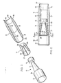
- the bullet according to the invention is made consisting of a sabot base part 10, a three-part annular wedge 11 and a tubular projectile body 12.
- the sabot base part 10 consists of a cylindrical rear section 13, a central conical or conical section 14 and a front cylindrical section, which is referred to as head 15.
- the conical middle section 14 of the sabot base part 10 is surrounded by the three-part annular wedge 11.
- the sabot base part 10 projects with the head 15 and the central conical section 14 into the interior of the tubular projectile body 12.
- Both the inner wall and the outer wall of the tubular projectile body 12 consist of three sections, namely a cylindrical inner wall 16, a cylindrical outer wall 17, one front conical inner wall 18, a front conical outer wall 19, a rear conical inner wall 20 and a rear conical outer wall 21.
- the front inner wall 18 and the front outer wall 19 form a sharp edge 22.
- the rear outer wall 21 and the rear inner wall 20 define one narrow annular end face 23.
- the three-part annular wedge 11 has a conical outer wall 24 and a conical inner wall 25. These two walls 24 and 25 delimit a wider annular end face 26 at the front and a narrower annular end face 27 at the rear.
- the cone angle ⁇ is selected such that the annular wedge is self-locking in the tubular projectile body 12.
- the cone angle!, J is selected such that the annular wedge 11 does not bear against the conical section 14 of the sabot base part 10 in a self-locking manner.
- the smaller cone angle i3 ensures that after the projectile has been fired, the sabot base part 10 reliably moves away from the projectile body 12, i.e. can detach from the annular wedge 11.
- the annular wedge 11 can reliably detach itself from the tubular projectile body 12, although the cone angle oC is selected such that the annular wedge 11 is self-locking in the tubular projectile body 12.
- the conical outer wall 24 and the conical inner wall 25 of the annular wedge can be provided with an oxalic layer.
- a plastic layer or a lubricating layer e.g. Fat or graphite.
- An air gap between the parts of the annular wedge 11 facilitates detachment from the projectile body 12.
Landscapes
- Physics & Mathematics (AREA)
- Fluid Mechanics (AREA)
- Engineering & Computer Science (AREA)
- General Engineering & Computer Science (AREA)
- Aiming, Guidance, Guns With A Light Source, Armor, Camouflage, And Targets (AREA)
- Input Circuits Of Receivers And Coupling Of Receivers And Audio Equipment (AREA)
- Pharmaceuticals Containing Other Organic And Inorganic Compounds (AREA)
Applications Claiming Priority (2)
| Application Number | Priority Date | Filing Date | Title |
|---|---|---|---|
| CH3307/81 | 1981-05-21 | ||
| CH330781 | 1981-05-21 |
Publications (2)
| Publication Number | Publication Date |
|---|---|
| EP0069809A1 true EP0069809A1 (fr) | 1983-01-19 |
| EP0069809B1 EP0069809B1 (fr) | 1985-02-13 |
Family
ID=4253152
Family Applications (1)
| Application Number | Title | Priority Date | Filing Date |
|---|---|---|---|
| EP81201324A Expired EP0069809B1 (fr) | 1981-05-21 | 1981-12-04 | Projectile tubulaire |
Country Status (8)
| Country | Link |
|---|---|
| US (1) | US4413565A (fr) |
| EP (1) | EP0069809B1 (fr) |
| JP (1) | JPS57196100A (fr) |
| CA (1) | CA1188926A (fr) |
| DE (1) | DE3168973D1 (fr) |
| IL (1) | IL65668A (fr) |
| NO (1) | NO152385C (fr) |
| ZA (1) | ZA822614B (fr) |
Cited By (2)
| Publication number | Priority date | Publication date | Assignee | Title |
|---|---|---|---|---|
| GB2130691A (en) * | 1982-11-24 | 1984-06-06 | Mauser Werke Oberndorf | Projectile with a tubular body |
| EP0361412A3 (fr) * | 1988-09-29 | 1990-09-26 | Mauser-Werke Oberndorf GmbH | Munition sous-calibrée |
Families Citing this family (11)
| Publication number | Priority date | Publication date | Assignee | Title |
|---|---|---|---|---|
| US5175389A (en) * | 1992-01-07 | 1992-12-29 | Federal-Hoffman, Inc. D/B/A Federal Cartridge Co. | Frontally guided sabot bullet |
| US5479861A (en) * | 1994-01-03 | 1996-01-02 | Kinchin; Anthony E. | Projectile with sabot |
| JP3038675B1 (ja) * | 1998-11-19 | 2000-05-08 | 西村 ムツ子 | ミサイル迎撃用の機関銃等の弾丸 |
| US7987790B1 (en) * | 2003-03-18 | 2011-08-02 | Scarr Kimball R | Ring airfoil glider expendable cartridge and glider launching method |
| US8661983B1 (en) | 2007-07-26 | 2014-03-04 | Kimball Rustin Scarr | Ring airfoil glider with augmented stability |
| US8065961B1 (en) | 2007-09-18 | 2011-11-29 | Kimball Rustin Scarr | Less lethal ammunition |
| US8511232B2 (en) | 2010-06-10 | 2013-08-20 | Kimball Rustin Scarr | Multifire less lethal munitions |
| CN105737692B (zh) * | 2016-04-13 | 2017-10-10 | 北京理工大学 | 一种无尾翼弹体加速弹托及方法 |
| US10502515B2 (en) * | 2017-01-17 | 2019-12-10 | Raytheon Company | Launch piston brake |
| CN110806299B (zh) * | 2019-08-23 | 2021-08-31 | 西北核技术研究院 | 一种将重金属长杆弹发射到超高速的小口径弹托 |
| CN114234741B (zh) * | 2021-12-24 | 2024-12-17 | 内蒙金属材料研究所 | 一种易分离的弹托 |
Citations (4)
| Publication number | Priority date | Publication date | Assignee | Title |
|---|---|---|---|---|
| GB190503921A (en) * | 1905-02-24 | 1905-11-23 | William Henry Harvey | Improvements in Armour-piercing Projectiles. |
| FR398091A (fr) * | 1908-03-14 | 1909-05-26 | Philippe Ledent | Obus à allègement automatique et à résistance atmosphérique diminuée |
| US2386054A (en) * | 1942-04-16 | 1945-10-02 | William N Mcgee | Projectile |
| FR2365098A1 (fr) * | 1976-09-20 | 1978-04-14 | Rheinmetall Gmbh | Projectile annulaire stabilise par giration |
Family Cites Families (1)
| Publication number | Priority date | Publication date | Assignee | Title |
|---|---|---|---|---|
| US3024729A (en) * | 1948-04-24 | 1962-03-13 | Cornell Aeronautical Labor Inc | Ram jet projectile |
-
1981
- 1981-12-04 DE DE8181201324T patent/DE3168973D1/de not_active Expired
- 1981-12-04 EP EP81201324A patent/EP0069809B1/fr not_active Expired
-
1982
- 1982-02-01 JP JP57013407A patent/JPS57196100A/ja active Pending
- 1982-03-08 NO NO820729A patent/NO152385C/no unknown
- 1982-04-08 CA CA000400801A patent/CA1188926A/fr not_active Expired
- 1982-04-16 ZA ZA822614A patent/ZA822614B/xx unknown
- 1982-04-29 US US06/373,122 patent/US4413565A/en not_active Expired - Fee Related
- 1982-05-02 IL IL65668A patent/IL65668A/xx unknown
Patent Citations (4)
| Publication number | Priority date | Publication date | Assignee | Title |
|---|---|---|---|---|
| GB190503921A (en) * | 1905-02-24 | 1905-11-23 | William Henry Harvey | Improvements in Armour-piercing Projectiles. |
| FR398091A (fr) * | 1908-03-14 | 1909-05-26 | Philippe Ledent | Obus à allègement automatique et à résistance atmosphérique diminuée |
| US2386054A (en) * | 1942-04-16 | 1945-10-02 | William N Mcgee | Projectile |
| FR2365098A1 (fr) * | 1976-09-20 | 1978-04-14 | Rheinmetall Gmbh | Projectile annulaire stabilise par giration |
Cited By (2)
| Publication number | Priority date | Publication date | Assignee | Title |
|---|---|---|---|---|
| GB2130691A (en) * | 1982-11-24 | 1984-06-06 | Mauser Werke Oberndorf | Projectile with a tubular body |
| EP0361412A3 (fr) * | 1988-09-29 | 1990-09-26 | Mauser-Werke Oberndorf GmbH | Munition sous-calibrée |
Also Published As
| Publication number | Publication date |
|---|---|
| IL65668A (en) | 1985-04-30 |
| CA1188926A (fr) | 1985-06-18 |
| DE3168973D1 (en) | 1985-03-28 |
| NO820729L (no) | 1982-11-22 |
| US4413565A (en) | 1983-11-08 |
| NO152385C (no) | 1985-09-18 |
| NO152385B (no) | 1985-06-10 |
| JPS57196100A (en) | 1982-12-01 |
| EP0069809B1 (fr) | 1985-02-13 |
| ZA822614B (en) | 1983-02-23 |
Similar Documents
| Publication | Publication Date | Title |
|---|---|---|
| DE3009342C2 (fr) | ||
| EP0069809A1 (fr) | Projectile tubulaire | |
| DE1227805B (de) | Manoeverpatronen-Zerfallgeschoss | |
| DE1703816B2 (de) | Treibspiegelgeschoss | |
| DE1578123C3 (de) | Abwerfbare Spitze für Geschosse mit durchgehender axialer Bohrung | |
| EP0072584B1 (fr) | Liaison entre l'enveloppe et la partie arrière d'un sabot pour projectile | |
| DE2617191A1 (de) | Spreizduebel | |
| DE2143605A1 (de) | Patrone und Verfahren zu deren Her stellung | |
| DE3309533A1 (de) | Fluegelstabilisiertes geschoss mit treibkaefig | |
| DE1026666B (de) | Patrone mit Leitwerkgeschoss | |
| DE2214092A1 (de) | Manoever-platzpatrone | |
| DE1905294C3 (fr) | ||
| DE671226C (de) | Metallpatronengurt | |
| EP0238817A1 (fr) | Projectile du type à sabot dont la partie arrière et le manchon qui composent ledit sabot comportent une fixation à ligne de rupture | |
| DE1905294B2 (de) | Geschoss | |
| DE2804311A1 (de) | Jagdgeschoss, insbesondere fuer grosswild | |
| DE10061068B4 (de) | Verpackungsbehälter mit einer darin befindlichen großkalibrigen Patrone | |
| EP0288657B1 (fr) | Projectile sous-calibré | |
| DE3150384C2 (de) | Anordnung zum Einbringen eines fliegenden Ziehstopfens | |
| DE3408817C2 (de) | Manöverpatrone mit Sollbruchbereich | |
| DE3207121A1 (de) | Ladesystem | |
| DE2400730A1 (de) | Verfahren und vorrichtung zum herausziehen einer patronenhuelse | |
| DE2704602C2 (de) | Hilfsvorrichtung für das Auswerfen von kurzen Treibladungshülsen bzw. Hülsenstummeln an Waffenanlagen | |
| DE3047316C2 (fr) | ||
| DE2159941C3 (de) | Elektrische Kontakteinrichtung für eine Rakete |
Legal Events
| Date | Code | Title | Description |
|---|---|---|---|
| PUAI | Public reference made under article 153(3) epc to a published international application that has entered the european phase |
Free format text: ORIGINAL CODE: 0009012 |
|
| AK | Designated contracting states |
Designated state(s): BE CH DE FR GB IT LI NL SE |
|
| 17P | Request for examination filed |
Effective date: 19830127 |
|
| ITF | It: translation for a ep patent filed | ||
| GRAA | (expected) grant |
Free format text: ORIGINAL CODE: 0009210 |
|
| AK | Designated contracting states |
Designated state(s): BE CH DE FR GB IT LI NL SE |
|
| REF | Corresponds to: |
Ref document number: 3168973 Country of ref document: DE Date of ref document: 19850328 |
|
| ET | Fr: translation filed | ||
| PG25 | Lapsed in a contracting state [announced via postgrant information from national office to epo] |
Ref country code: SE Effective date: 19851205 |
|
| PLBE | No opposition filed within time limit |
Free format text: ORIGINAL CODE: 0009261 |
|
| STAA | Information on the status of an ep patent application or granted ep patent |
Free format text: STATUS: NO OPPOSITION FILED WITHIN TIME LIMIT |
|
| PG25 | Lapsed in a contracting state [announced via postgrant information from national office to epo] |
Ref country code: LI Effective date: 19851231 Ref country code: CH Effective date: 19851231 Ref country code: BE Effective date: 19851231 |
|
| 26N | No opposition filed | ||
| BERE | Be: lapsed |
Owner name: WERKZEUGMASCHINENFABRIK OERLIKON BUHRLE A.G. Effective date: 19851231 |
|
| PG25 | Lapsed in a contracting state [announced via postgrant information from national office to epo] |
Ref country code: NL Effective date: 19860701 |
|
| GBPC | Gb: european patent ceased through non-payment of renewal fee | ||
| NLV4 | Nl: lapsed or anulled due to non-payment of the annual fee | ||
| PG25 | Lapsed in a contracting state [announced via postgrant information from national office to epo] |
Ref country code: FR Free format text: LAPSE BECAUSE OF NON-PAYMENT OF DUE FEES Effective date: 19860829 |
|
| REG | Reference to a national code |
Ref country code: CH Ref legal event code: PL |
|
| PG25 | Lapsed in a contracting state [announced via postgrant information from national office to epo] |
Ref country code: DE Effective date: 19860902 |
|
| REG | Reference to a national code |
Ref country code: FR Ref legal event code: ST |
|
| PG25 | Lapsed in a contracting state [announced via postgrant information from national office to epo] |
Ref country code: GB Effective date: 19881121 |
|
| EUG | Se: european patent has lapsed |
Ref document number: 81201324.1 Effective date: 19860826 |