EP0069845A2 - Compresseur à pistons radiaux - Google Patents
Compresseur à pistons radiaux Download PDFInfo
- Publication number
- EP0069845A2 EP0069845A2 EP82104321A EP82104321A EP0069845A2 EP 0069845 A2 EP0069845 A2 EP 0069845A2 EP 82104321 A EP82104321 A EP 82104321A EP 82104321 A EP82104321 A EP 82104321A EP 0069845 A2 EP0069845 A2 EP 0069845A2
- Authority
- EP
- European Patent Office
- Prior art keywords
- cylinder block
- fixed axis
- pressure
- piston compressor
- gap
- Prior art date
- Legal status (The legal status is an assumption and is not a legal conclusion. Google has not performed a legal analysis and makes no representation as to the accuracy of the status listed.)
- Granted
Links
Images

Classifications
-
- F—MECHANICAL ENGINEERING; LIGHTING; HEATING; WEAPONS; BLASTING
- F04—POSITIVE - DISPLACEMENT MACHINES FOR LIQUIDS; PUMPS FOR LIQUIDS OR ELASTIC FLUIDS
- F04B—POSITIVE-DISPLACEMENT MACHINES FOR LIQUIDS; PUMPS
- F04B27/00—Multi-cylinder pumps specially adapted for elastic fluids and characterised by number or arrangement of cylinders
- F04B27/04—Multi-cylinder pumps specially adapted for elastic fluids and characterised by number or arrangement of cylinders having cylinders in star- or fan-arrangement
- F04B27/0404—Details, component parts specially adapted for such pumps
- F04B27/0423—Cylinders
-
- F—MECHANICAL ENGINEERING; LIGHTING; HEATING; WEAPONS; BLASTING
- F04—POSITIVE - DISPLACEMENT MACHINES FOR LIQUIDS; PUMPS FOR LIQUIDS OR ELASTIC FLUIDS
- F04B—POSITIVE-DISPLACEMENT MACHINES FOR LIQUIDS; PUMPS
- F04B27/00—Multi-cylinder pumps specially adapted for elastic fluids and characterised by number or arrangement of cylinders
- F04B27/04—Multi-cylinder pumps specially adapted for elastic fluids and characterised by number or arrangement of cylinders having cylinders in star- or fan-arrangement
- F04B27/0404—Details, component parts specially adapted for such pumps
- F04B27/0451—Particularities relating to the distribution members
- F04B27/0456—Particularities relating to the distribution members to cylindrical distribution members
-
- F—MECHANICAL ENGINEERING; LIGHTING; HEATING; WEAPONS; BLASTING
- F04—POSITIVE - DISPLACEMENT MACHINES FOR LIQUIDS; PUMPS FOR LIQUIDS OR ELASTIC FLUIDS
- F04B—POSITIVE-DISPLACEMENT MACHINES FOR LIQUIDS; PUMPS
- F04B27/00—Multi-cylinder pumps specially adapted for elastic fluids and characterised by number or arrangement of cylinders
- F04B27/04—Multi-cylinder pumps specially adapted for elastic fluids and characterised by number or arrangement of cylinders having cylinders in star- or fan-arrangement
- F04B27/06—Multi-cylinder pumps specially adapted for elastic fluids and characterised by number or arrangement of cylinders having cylinders in star- or fan-arrangement the cylinders being movable, e.g. rotary
- F04B27/0606—Multi-cylinder pumps specially adapted for elastic fluids and characterised by number or arrangement of cylinders having cylinders in star- or fan-arrangement the cylinders being movable, e.g. rotary having cylinders in star- or fan-arrangement, the connection of the pistons with an actuating element being at the outer ends of the cylinders
- F04B27/0612—Multi-cylinder pumps specially adapted for elastic fluids and characterised by number or arrangement of cylinders having cylinders in star- or fan-arrangement the cylinders being movable, e.g. rotary having cylinders in star- or fan-arrangement, the connection of the pistons with an actuating element being at the outer ends of the cylinders rotary cylinder block
- F04B27/0619—Multi-cylinder pumps specially adapted for elastic fluids and characterised by number or arrangement of cylinders having cylinders in star- or fan-arrangement the cylinders being movable, e.g. rotary having cylinders in star- or fan-arrangement, the connection of the pistons with an actuating element being at the outer ends of the cylinders rotary cylinder block cylinder block and actuating cam rotating together
Definitions
- the invention relates to a radial piston compressor, with pistons which can be moved radially back and forth in the piston chambers of a cylinder block rotatably mounted on a fixed axis, the radial movement of which is controlled by a rotatable guide part arranged with its axis of rotation eccentrically to the axis of rotation of the cylinder block, in the region of which from the cylinder block on the fixed axis covered area each a suction and pressure slot extending over a partial circumference of the fixed axis is provided and oil is introduced into the gap existing between the cylinder block and the fixed axis, in which the individual piston spaces in their the fixed Axis adjacent floor have an opening that is at least on the bottom side facing the axis in the same plane as the suction and pressure slot.
- Such a radial piston compressor is known from DE-PS 27 10 734.
- oil is also sucked in when the medium to be compressed is sucked in, which also passes between the cylinder block and the fixed axis via the opening in the bottom of the piston chambers and seals gaps present here. It has now been shown that the sealing effect of the oil thus obtained between the cylinder block and the fixed axis is unsatisfactory.
- the compressed gas displaces the oil and blows it out of the gap between the cylinder block and the fixed axis.
- the invention has for its object to design a radial piston compressor of the type described above Design that a perfect seal is achieved by the oil located between the cylinder block and the fixed axis.
- the gap has a decreasing cross section in the direction from the suction slot to the pressure slot and the oil is introduced into the gap in the region of the largest gap cross section. Due to its viscosity, the oil is carried along by the rotating cylinder block.
- the reduction in the gap cross section at least at one point leads to an increase in the pressure acting on the oil, which can be made equal or greater than the pressure increase of the gas to be compressed by appropriately dimensioning the reduction in cross section. Since the oil located between the cylinder block and the fixed axle is now under high pressure, it can no longer be blown out of the gap by the gas to be compressed.
- a gap which decreases in cross section towards the pressure slot is achieved in a simple manner in that at least one of the cylinder block is spaced in the fixed axis on both sides of the suction slot covered groove is provided, which extends in the circumferential direction starting from the beginning of the suction slot at least to the end of the pressure slot and whose depth and / or width decreases from the suction slot to the pressure slot.
- a gap which decreases in cross section can be provided in a radial piston compressor by means of a roller Bearing mounted on the fixed axis cylinder block can also be achieved in that the roller bearing is arranged eccentrically with respect to the fixed axis.
- the reduction in the gap is determined by the design. If the compressor works with different gas pressures, the reduction in cross-section of the gap must be such that the hydrodynamically generated oil pressure corresponds approximately to the highest compressor pressure of the gas. If the compressor works with low compression pressures, however, the oil penetrates against the gas due to the higher pressure and flows off to the piston chambers. The oil entering the piston chambers is pushed out together with the gas at the end of the compression stroke, which can lead to oil strikes. In order to prevent the oil from penetrating into the piston chambers, an automatic adjustment of the respective oil pressure to the compression pressure is necessary.
- such an automatic adaptation is achieved in that the surface E covered by the cylinder block is formed on the fixed axis as a bearing surface on which the cylinder block is directly rotatably supported.
- the radial load of the cylinder block averaged over the circumference as the reaction force of the piston forces is approximately proportional to that of the gas.
- the cylinder block adjusts itself to the fixed axis under this radial load in such a way that the pressure force which builds up hydrodynamically in the gap between the cylinder block and the fixed axis is in equilibrium with this radial load.
- the higher the compression pressure the greater the radial force and thus also the eccentricity between the cylinder block and the fixed axle and ultimately the oil pressure.
- With a suitable width of the sealing gap it can thus be achieved that in a wide pressure range the hydrodynamic oil pressure is in the order of magnitude of the corresponding compression pressure of the respective piston.
- At least one channel is provided on both sides of the suction slot, the cross-section of which is larger than the largest possible cross-section of the gap existing between the cylinder block and the fixed axis and into the front, as seen in the direction of rotation End oil is introduced.
- the oil pressure is raised slightly above the suction pressure towards the end of the suction slot.
- the oil pressure then increases in proportion to the compression pressure towards the pressure slot.
- An increase in the oil pressure in the channel is achieved by the fact that it has a reduced cross-section towards the end of the suction slot.
- the sealing effect of the oil films can still be improved in that the 'cylinder block and the fixed axis are arranged in a closed pressure-resistant housing and the pressure in the housing is between the suction pressure and the compression pressure of the compressor.
- a pressure equilibrium is established in such a closed housing under the effect of gap losses flowing in on the compression side and on the suction side.
- a certain pressure is required in the housing in order to minimize the gap and ventilation losses.
- Such a pressure can be set in the housing in a simple manner in that a passage opening into the housing space is provided on the fixed axis in the peripheral region lying between the suction and pressure slot. The passage is arranged in the peripheral area at the point where the desired pressure prevails in the piston spaces.
- the bell is expediently attached to the laminated core of the external rotor. Little assembly effort results in that the bell is made in one piece with the short-circuit ring of the external rotor. Since such a bell has a smooth surface, only slight friction losses occur, so that the ventilation losses are also reduced by such a bell.
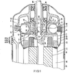
- the radial piston compressor consists of a cylinder block 2 rotatably arranged on a fixed axis 1.
- a plurality of cylindrical piston chambers 3 are formed on cylinder block 2, distributed uniformly over its circumference.
- a freely movable piston 4 is arranged in each piston chamber 3.
- the pistons 4 consist of a cup-shaped support part 5, into which a ball 6 is inserted, which rolls on a guide ring 7.
- the guide ring 7 is carried by a guide part 8, which is mounted eccentrically on the fixed axis 1 with respect to the cylinder block 2.
- an external rotor motor is provided as the drive motor 11, the inner stand 9 of which is fixed on the fixed axis 1.
- the external rotor 10 is coupled to the cylinder block 2 via arms 13 connected to the short-circuit ring 12 in question on the end face. That from the radial piston.
- Compressor and the drive motor 11. Compressor unit is inserted into a pressure-resistant housing 14.
- the fixed axis 1 is hollow and serves as a feed channel 15 for the gas to be compressed.
- the feed channel 15 is connected to the suction slot 17 of the radial piston compressor.
- the surface covered by the cylinder block 2 on the fixed axis 1 is designed as a bearing surface 19.
- the cylinder block 2 is directly supported on this bearing surface 19 by means of a ring 21 on which the individual cylinders 20 are arranged.
- the ring 21 also forms the bottom of the piston spaces 3 .
- an opening 22 is provided which overlaps with the suction or pressure slot 17 or 18.
- FIG. 2 shows the surface 26 of the fixed axis 1 covered by the cylinder block 2 in one development.
- the suction slot 17 extends almost to the bottom dead center UT.
- the pressure slot 18 is much shorter and ends at the top dead center OT.
- the gas is compressed on the route between the suction and pressure slots 17 and 18.
- a groove 27 is formed on each side of the suction slit 17 and extends beyond the pressure slit 18. In the area between the suction and pressure slots 17 and 18, the groove 27 is reduced in its cross section by two width gradations 28 and, as the sectional illustration according to FIG. 3 shows, by several depth gradations 29, that through the transverse bore 25 in the groove 27 Oil brought in is carried along by the cylinder block 2.
- the oil is exposed to an ever higher pressure, which corresponds approximately to the compression pressure built up between the suction and pressure slots 17 and 18, or even higher if the groove cross-section is dimensioned accordingly than the compression pressure of the gas.
- the provision of the described grooves 27 on both sides of the suction slot 17 and the pressure slot 18 is particularly advantageous in the case of a radial piston compressor, in which the cylinder block 2 is mounted on the fixed axis 1 by means of a roller bearing.
- a groove 30 is formed on both sides of the suction opening 17 in the fixed axis 1.
- the cross bores 25 connected to the bore channel 24 in turn open into the two channels 30.
- the channels 30 have e.g. a depth gradation 31 and at its end, as can be seen from FIG. 5, end in a slope 32.
- the reduction in cross-section of the channel 30 caused by the depth gradation 31 and / or the bevel 32 in turn leads to a pressure increase in the oil introduced into the channel 30 via the transverse bore 25.
- the troughs 30 only extend approximately to the end of the suction slot 17.
- An increase in the oil pressure at the end of the trough 30 is also achieved when the cross-sectional area is not reduced within the trough 30, but rather the cross section of the gap between the cylinder block 2 and the fixed axis 1 following the channel 30 is smaller than the channel cross section. Since the cylinder block 2 is mounted directly on the bearing surface 19, an eccentric adjustment of the cylinder block relative to the bearing surface 19 takes place due to the compression pressure prevailing in the piston chambers. This eccentric adjustment results in a ring between the ring 21 of the cylinder block 2 and the bearing surface 19 Widening gap from the suction slot 17 to the pressure slot 18. In the channels 30 with reduced cross-section, the oil pressure is already raised slightly above the suction pressure of the gas towards the end of the suction slot 17. As a result of the gap narrowing further towards the pressure slot 18, the oil pressure and the compression pressure of the gas in the piston chambers 3 constantly increase.
- a transverse slot 33 is formed in the bearing surface 19, which is at least below the Opening 22 in the bottom of the piston chambers 3 is sufficient.
- a connection between the transverse slot 33 and the outer space surrounding the compressor is established via an axial bore 34.
- a satisfactory seal between the cylinder block 2 and the bearing surface 19 is achieved by an increase in the oil pressure in the gap existing between the cylinder block 2 and the bearing surface 19 corresponding to the increasing compression pressure between the suction and the pressure slots 17 and 18.
- the increase in the oil pressure can be brought about by various measures. If the cylinder block 2 is mounted on the fixed axis by means of a roller bearing, 17 grooves 27 are provided on both sides of the suction slot, the cross section of which is reduced towards the pressure slot 18. As a result of this reduction in cross section, there is an increase in pressure for the oil entrained by the cylinder block 2.
- the rolling bearing and the formation of the grooves 27 define both the dimensions of the gap between the cylinder block 2 and the surface 26 of the fixed axis 1 that it covers, and the reduction in cross section of the grooves 27. Accordingly, the same oil pressure is always generated regardless of the respective compression pressure. By appropriately designing the cross section of the grooves 27, this oil pressure can be dimensioned such that it is above the highest compression pressure. If the compressor works with lower ver directional pressure, then there is a risk that the oil penetrates into the piston chambers 3.
- a pressure between the intake pressure and the compression pressure is established in the pressure-resistant housing 14 surrounding the compressor unit. Since gases which have a higher specific weight than air are often compressed in such radial piston compressors, the ventilation losses also increase sharply with the increased pressure in the pressure-resistant housing 14. To reduce these ventilation losses, a bell 35 is attached to the outer rotor 10 of the drive motor 11, which bell covers the cylinder block 2 at least partially.
- the gas located in the interior of the bell 35 is set in rotation and has only a low relative speed with respect to the likewise rotating cylinder block 2, so that there is also only a small ventilation ver lusts result.
- only slight ventilation losses occur on the smooth outside of the bell 35 compared to the gas located in the pressure-resistant housing 14.
- the bell 35 can be made together with the short-circuit ring 12 and the arms 13 in one operation. If the wall of the bell 35 is inclined slightly outwards towards the open end of the bell, such a bell can be used to separate contaminants present in the oil. The oil emerging from the gap between the cylinder block 2 and the bearing surface 19 drips or splashes into the bell 35. The centrifugal force caused by the rotation of the bell 35 allows the oil to flow off on the outwardly inclined wall of the bell 35 towards its open end . On the other hand, the impurities that are heavier than the oil stick to the bell wall. The cleaning effect can be improved further by designing the bell wall accordingly, for example by attaching a rough covering or one or more circumferential grooves.
Landscapes
- Engineering & Computer Science (AREA)
- Mechanical Engineering (AREA)
- General Engineering & Computer Science (AREA)
- Compressor (AREA)
- Compressors, Vaccum Pumps And Other Relevant Systems (AREA)
Priority Applications (1)
| Application Number | Priority Date | Filing Date | Title |
|---|---|---|---|
| AT82104321T ATE29769T1 (de) | 1981-05-25 | 1982-05-17 | Radialkolbenverdichter. |
Applications Claiming Priority (2)
| Application Number | Priority Date | Filing Date | Title |
|---|---|---|---|
| DE3120812A DE3120812C2 (de) | 1981-05-25 | 1981-05-25 | Radialkolbenverdichter |
| DE3120812 | 1981-05-25 |
Publications (3)
| Publication Number | Publication Date |
|---|---|
| EP0069845A2 true EP0069845A2 (fr) | 1983-01-19 |
| EP0069845A3 EP0069845A3 (en) | 1984-02-22 |
| EP0069845B1 EP0069845B1 (fr) | 1987-09-16 |
Family
ID=6133195
Family Applications (1)
| Application Number | Title | Priority Date | Filing Date |
|---|---|---|---|
| EP82104321A Expired EP0069845B1 (fr) | 1981-05-25 | 1982-05-17 | Compresseur à pistons radiaux |
Country Status (7)
| Country | Link |
|---|---|
| US (1) | US4465436A (fr) |
| EP (1) | EP0069845B1 (fr) |
| JP (1) | JPS57200688A (fr) |
| AT (1) | ATE29769T1 (fr) |
| DE (2) | DE3120812C2 (fr) |
| DK (1) | DK151146C (fr) |
| IE (1) | IE53119B1 (fr) |
Cited By (2)
| Publication number | Priority date | Publication date | Assignee | Title |
|---|---|---|---|---|
| DE3431158A1 (de) * | 1984-08-24 | 1986-03-06 | Alfred Teves Gmbh, 6000 Frankfurt | Radialkolbenmaschine, insbesondere kugelkolbenpumpe |
| EP3489511A1 (fr) * | 2017-11-28 | 2019-05-29 | Hoerbiger Automotive Komfortsysteme GmbH | Système hydraulique |
Families Citing this family (8)
| Publication number | Priority date | Publication date | Assignee | Title |
|---|---|---|---|---|
| DE3316106A1 (de) * | 1983-05-03 | 1984-11-08 | Siemens AG, 1000 Berlin und 8000 München | Radialkolbenverdichter |
| JPH0631633B2 (ja) * | 1987-08-12 | 1994-04-27 | 株式会社ユニシアジェックス | タ−ビン型燃料ポンプ |
| US5979440A (en) | 1997-06-16 | 1999-11-09 | Sequal Technologies, Inc. | Methods and apparatus to generate liquid ambulatory oxygen from an oxygen concentrator |
| US5988165A (en) * | 1997-10-01 | 1999-11-23 | Invacare Corporation | Apparatus and method for forming oxygen-enriched gas and compression thereof for high-pressure mobile storage utilization |
| US7204249B1 (en) * | 1997-10-01 | 2007-04-17 | Invcare Corporation | Oxygen conserving device utilizing a radial multi-stage compressor for high-pressure mobile storage |
| US8062003B2 (en) * | 2005-09-21 | 2011-11-22 | Invacare Corporation | System and method for providing oxygen |
| WO2011022361A1 (fr) * | 2009-08-17 | 2011-02-24 | Invacare Corporation | Compresseur |
| EP2809949A4 (fr) | 2012-02-03 | 2015-12-09 | Invacare Corp | Dispositif de pompage |
Family Cites Families (12)
| Publication number | Priority date | Publication date | Assignee | Title |
|---|---|---|---|---|
| US1888860A (en) * | 1927-07-26 | 1932-11-22 | Arthur J Kercher | Compressor |
| US1846360A (en) * | 1928-01-27 | 1932-02-23 | Walter H Rudolph | Compressor |
| US1939057A (en) * | 1930-02-24 | 1933-12-12 | Arthur J Kercher | Compressor |
| DE720485C (de) * | 1936-10-07 | 1942-05-07 | Gustav Stromeier | Foerdereinrichtung fuer Fluessigkeiten |
| US2515033A (en) * | 1948-05-25 | 1950-07-11 | Connor Arthur Albert | Reciprocating pump and compressor |
| US3037457A (en) * | 1959-08-26 | 1962-06-05 | Gen Electric | Pumps |
| US3357361A (en) * | 1965-10-21 | 1967-12-12 | Bendix Corp | High velocity pump |
| DE2239757A1 (de) * | 1972-08-12 | 1974-02-21 | Bosch Gmbh Robert | Radialkolbenmaschine |
| DE2248312C3 (de) * | 1972-10-02 | 1978-07-06 | Robert Bosch Gmbh, 700 Stuttgart | Hydrostatische Radialkolbenmaschine |
| DE2710734B2 (de) * | 1977-03-11 | 1979-02-08 | Siemens Ag, 1000 Berlin Und 8000 Muenchen | Verdichteraggregat, bestehend aus einem Antriebsmotor und einem Verdichter mit exzentrisch geführten, frei beweglichen Kolben |
| DE2832017A1 (de) * | 1978-07-20 | 1980-01-31 | Siemens Ag | Verdichteraggregat, bestehend aus einem antriebsmotor und einem radialkolbenverdichter |
| CH638590A5 (de) * | 1979-02-26 | 1983-09-30 | Sulzer Ag | Hydrostatische kolbenmaschine. |
-
1981
- 1981-05-25 DE DE3120812A patent/DE3120812C2/de not_active Expired
-
1982
- 1982-05-17 DE DE8282104321T patent/DE3277321D1/de not_active Expired
- 1982-05-17 EP EP82104321A patent/EP0069845B1/fr not_active Expired
- 1982-05-17 AT AT82104321T patent/ATE29769T1/de not_active IP Right Cessation
- 1982-05-18 US US06/379,553 patent/US4465436A/en not_active Expired - Fee Related
- 1982-05-24 IE IE1236/82A patent/IE53119B1/en unknown
- 1982-05-24 DK DK232082A patent/DK151146C/da not_active IP Right Cessation
- 1982-05-25 JP JP57088721A patent/JPS57200688A/ja active Pending
Cited By (2)
| Publication number | Priority date | Publication date | Assignee | Title |
|---|---|---|---|---|
| DE3431158A1 (de) * | 1984-08-24 | 1986-03-06 | Alfred Teves Gmbh, 6000 Frankfurt | Radialkolbenmaschine, insbesondere kugelkolbenpumpe |
| EP3489511A1 (fr) * | 2017-11-28 | 2019-05-29 | Hoerbiger Automotive Komfortsysteme GmbH | Système hydraulique |
Also Published As
| Publication number | Publication date |
|---|---|
| DK232082A (da) | 1982-11-26 |
| DK151146B (da) | 1987-11-09 |
| DE3277321D1 (de) | 1987-10-22 |
| DK151146C (da) | 1988-07-18 |
| DE3120812C2 (de) | 1984-04-19 |
| IE821236L (en) | 1982-11-25 |
| IE53119B1 (en) | 1988-07-06 |
| EP0069845A3 (en) | 1984-02-22 |
| US4465436A (en) | 1984-08-14 |
| EP0069845B1 (fr) | 1987-09-16 |
| DE3120812A1 (de) | 1982-12-23 |
| JPS57200688A (en) | 1982-12-08 |
| ATE29769T1 (de) | 1987-10-15 |
Similar Documents
| Publication | Publication Date | Title |
|---|---|---|
| DE3237803A1 (de) | Rotationskompressor | |
| DE1525193C3 (de) | Pneumo- oder hydrostatisches Lager | |
| DE3248407A1 (de) | Schneckenverdichter | |
| DE2909157A1 (de) | Rotationsverdichter | |
| EP0069845B1 (fr) | Compresseur à pistons radiaux | |
| DE4441915C2 (de) | Innenzahnradpumpe | |
| DE3343908A1 (de) | Maschine, insbesondere arbeitsmaschine zum verdichten und foerdern von fluiden aller art | |
| DE4002221C2 (de) | Taumelscheibenkompressor mit Drucklagerschmierung | |
| DE69815001T2 (de) | Wasserpumpe und ihr Herstellungsverfahren | |
| DE2710734A1 (de) | Verdichter mit exzentrisch gefuehrten, frei beweglichen kolben | |
| DE2328365C2 (de) | Vakuumrotationspumpe | |
| DE2542803C2 (de) | Verbrennungsmotor mit liegenden Zylindern, und Kolben für derartige Motoren | |
| DE2203278A1 (de) | Axialkolbenmaschine | |
| DE2351856C3 (fr) | ||
| DE8115575U1 (de) | Radialkolbenverdichter | |
| DE676147C (de) | Pumpe zum Foerdern von fluessigen Brennstoffen | |
| DE2311048C3 (de) | Verdichterkolben | |
| DE3245974C2 (fr) | ||
| DE3152386C2 (de) | Radialkolbenverdichter | |
| DE19704752A1 (de) | Nadellager, insbesondere für eine Radialkolbenpumpe | |
| DE2263837A1 (de) | Radialkolbenpumpe | |
| DE2805492A1 (de) | Anordnung zum kuehlen der kolben bei einer axialkolbenmaschine | |
| DE3729319C2 (de) | Spiralverdichter | |
| DE10224428A1 (de) | Kolbenverdichter, insbesondere hermetisch gekapselter Kältemittelverdichter | |
| DE3246782C2 (fr) |
Legal Events
| Date | Code | Title | Description |
|---|---|---|---|
| PUAI | Public reference made under article 153(3) epc to a published international application that has entered the european phase |
Free format text: ORIGINAL CODE: 0009012 |
|
| AK | Designated contracting states |
Designated state(s): AT BE CH DE FR GB IT LI NL SE |
|
| PUAL | Search report despatched |
Free format text: ORIGINAL CODE: 0009013 |
|
| AK | Designated contracting states |
Designated state(s): AT BE CH DE FR GB IT LI NL SE |
|
| 17P | Request for examination filed |
Effective date: 19840329 |
|
| GRAA | (expected) grant |
Free format text: ORIGINAL CODE: 0009210 |
|
| AK | Designated contracting states |
Kind code of ref document: B1 Designated state(s): AT BE CH DE FR GB IT LI NL SE |
|
| REF | Corresponds to: |
Ref document number: 29769 Country of ref document: AT Date of ref document: 19871015 Kind code of ref document: T |
|
| PG25 | Lapsed in a contracting state [announced via postgrant information from national office to epo] |
Ref country code: SE Effective date: 19870930 |
|
| REF | Corresponds to: |
Ref document number: 3277321 Country of ref document: DE Date of ref document: 19871022 |
|
| ET | Fr: translation filed | ||
| ITF | It: translation for a ep patent filed | ||
| GBT | Gb: translation of ep patent filed (gb section 77(6)(a)/1977) | ||
| PLBE | No opposition filed within time limit |
Free format text: ORIGINAL CODE: 0009261 |
|
| STAA | Information on the status of an ep patent application or granted ep patent |
Free format text: STATUS: NO OPPOSITION FILED WITHIN TIME LIMIT |
|
| 26N | No opposition filed | ||
| PGFP | Annual fee paid to national office [announced via postgrant information from national office to epo] |
Ref country code: GB Payment date: 19890430 Year of fee payment: 8 |
|
| PGFP | Annual fee paid to national office [announced via postgrant information from national office to epo] |
Ref country code: AT Payment date: 19890503 Year of fee payment: 8 |
|
| PG25 | Lapsed in a contracting state [announced via postgrant information from national office to epo] |
Ref country code: LI Effective date: 19890531 Ref country code: CH Effective date: 19890531 Ref country code: BE Effective date: 19890531 |
|
| PG25 | Lapsed in a contracting state [announced via postgrant information from national office to epo] |
Ref country code: NL Effective date: 19891201 |
|
| NLV4 | Nl: lapsed or anulled due to non-payment of the annual fee | ||
| PG25 | Lapsed in a contracting state [announced via postgrant information from national office to epo] |
Ref country code: FR Free format text: LAPSE BECAUSE OF NON-PAYMENT OF DUE FEES Effective date: 19900131 |
|
| REG | Reference to a national code |
Ref country code: CH Ref legal event code: PL |
|
| PG25 | Lapsed in a contracting state [announced via postgrant information from national office to epo] |
Ref country code: DE Effective date: 19900201 |
|
| REG | Reference to a national code |
Ref country code: FR Ref legal event code: ST |
|
| PG25 | Lapsed in a contracting state [announced via postgrant information from national office to epo] |
Ref country code: GB Effective date: 19900517 Ref country code: AT Effective date: 19900517 |
|
| GBPC | Gb: european patent ceased through non-payment of renewal fee |