EP0069877A1 - Capteur à touche pour engendrer sans contact un signal électrique lors de la pression sur la touche - Google Patents
Capteur à touche pour engendrer sans contact un signal électrique lors de la pression sur la touche Download PDFInfo
- Publication number
- EP0069877A1 EP0069877A1 EP82105363A EP82105363A EP0069877A1 EP 0069877 A1 EP0069877 A1 EP 0069877A1 EP 82105363 A EP82105363 A EP 82105363A EP 82105363 A EP82105363 A EP 82105363A EP 0069877 A1 EP0069877 A1 EP 0069877A1
- Authority
- EP
- European Patent Office
- Prior art keywords
- core
- keyboard button
- toroidal
- toroidal core
- housing
- Prior art date
- Legal status (The legal status is an assumption and is not a legal conclusion. Google has not performed a legal analysis and makes no representation as to the accuracy of the status listed.)
- Granted
Links
- 238000004804 winding Methods 0.000 claims abstract description 18
- 229910000808 amorphous metal alloy Inorganic materials 0.000 claims abstract description 3
- 230000000994 depressogenic effect Effects 0.000 claims description 5
- 230000005291 magnetic effect Effects 0.000 abstract description 8
- 239000000463 material Substances 0.000 description 5
- 230000003068 static effect Effects 0.000 description 3
- 238000010276 construction Methods 0.000 description 2
- 230000000694 effects Effects 0.000 description 2
- 238000000418 atomic force spectrum Methods 0.000 description 1
- 230000007423 decrease Effects 0.000 description 1
- 230000001419 dependent effect Effects 0.000 description 1
- 238000010586 diagram Methods 0.000 description 1
- 230000006698 induction Effects 0.000 description 1
- 239000000696 magnetic material Substances 0.000 description 1
- 230000005415 magnetization Effects 0.000 description 1
- 239000000155 melt Substances 0.000 description 1
- 229910001092 metal group alloy Inorganic materials 0.000 description 1
Images




Classifications
-
- H—ELECTRICITY
- H03—ELECTRONIC CIRCUITRY
- H03K—PULSE TECHNIQUE
- H03K17/00—Electronic switching or gating, i.e. not by contact-making and –breaking
- H03K17/94—Electronic switching or gating, i.e. not by contact-making and –breaking characterised by the way in which the control signals are generated
- H03K17/965—Switches controlled by moving an element forming part of the switch
- H03K17/97—Switches controlled by moving an element forming part of the switch using a magnetic movable element
-
- H—ELECTRICITY
- H03—ELECTRONIC CIRCUITRY
- H03K—PULSE TECHNIQUE
- H03K17/00—Electronic switching or gating, i.e. not by contact-making and –breaking
- H03K17/51—Electronic switching or gating, i.e. not by contact-making and –breaking characterised by the components used
- H03K17/80—Electronic switching or gating, i.e. not by contact-making and –breaking characterised by the components used using non-linear magnetic devices; using non-linear dielectric devices
-
- H—ELECTRICITY
- H03—ELECTRONIC CIRCUITRY
- H03K—PULSE TECHNIQUE
- H03K17/00—Electronic switching or gating, i.e. not by contact-making and –breaking
- H03K17/94—Electronic switching or gating, i.e. not by contact-making and –breaking characterised by the way in which the control signals are generated
- H03K17/965—Switches controlled by moving an element forming part of the switch
- H03K17/97—Switches controlled by moving an element forming part of the switch using a magnetic movable element
- H03K2017/9706—Inductive element
Definitions
- the invention relates to a sensor key using a toroidal core made of an amorphous metal alloy provided with at least one electrical winding, in which the change in voltage in the winding due to deformation of the toroidal core represents a usable electrical signal.
- the object of the present invention is to provide a particularly advantageous arrangement for forming a sensor key using this known effect of converting mechanical force into an electrical signal.
- This object is achieved in that a stop is provided which is arranged in the vicinity of the toroidal core so that it rests against the stop when it is deformed, so that a sudden change in the compressive force is required for further deformation.
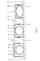
- FIGS. 1 to 3 Exemplary embodiments are shown schematically in FIGS. 1 to 3.
- FIG. 4 shows the hysteresis loop when the keyboard button is pressed and not pressed
- FIG. 5 shows the associated voltage curve at the input of the threshold value amplifier 11 connected to the winding 15 on both sides of the associated toroidal core.
- a plurality of housings 4 are mounted on a base plate 7, each of which is closed at the top by an attached keyboard button 1.
- Located inside each housing 4 each have a toroidal core 5 made of a soft magnetic amorphous material, which has good spring behavior in addition to good soft magnetic properties.
- the ring band cores 5 can consist of the following metal alloys quenched from a melt:
- three sensor buttons 8,9,10 are shown, the keyboard buttons 1 are depressed to different degrees.
- the keyboard button 1 of the sensor button 8 is not pressed, while the keyboard button 1 of the sensor button 9 has already covered a key stroke corresponding to the distance 2.
- the housing 4 is dimensioned such that when the keyboard button 1 is pressed down by a distance 2, the toroidal core 5 lies against the walls of the housing 4 on both sides. If the keyboard button 1 is pressed further down by an additional distance 3 - as shown with the sensor key 10 - the toroidal core 5 deforms with smaller radii of curvature, so that the resistance of the toroidal core 5 against pressing the keyboard button 1 down from that shown with the sensor key 2 Position in the position shown in the sensor button 3 is suddenly increased. This gives the sensor key according to the invention a pressure point without the need for an additional component.
- the sensor keys 8 to 10 in FIG. 1 can be part of a keyboard and are connected to a common winding 15 which is supplied with alternating current by a high-frequency alternating voltage source 14. At the winding 15 are in front and behind the input connections 16 and 17 of each threshold amplifier 11 are connected to each ring band core.
- the threshold amplifiers 11 are set so that either during the key stroke corresponding to distance 3 at the output 12 of the threshold amplifier 11, a voltage change occurs, which represents the signal for an electrical circuit connected to it, whether the respective sensor key is pressed or not.
- FIG. 2 shows another possibility for using the ring band core 5 both as a magnetic core, as a spring and as a component for achieving a pressure point.
- the sensor buttons 8, 9, 10 are again shown in FIG.
- the toroidal cores 5 each lie in a trough 6, the radius of curvature of which is greater than the radius of curvature of the toroidal core 5 when it is not deformed.
- the keyboard button 1 is pressed down by the distance 2 (sensor key 9)
- the lower half of the toroidal core 5 rests against the trough 6, so that a pressure point effect again arises when the keyboard button is pressed further down the distance 3.
- the sensor buttons 8, 9 and 10 are again shown in different positions; this embodiment differs from the rest in that two toroidal cores 5 and 13 are provided with different diameters. These ring band cores can be connected to one another at one point, it is also possible to wind them from a single band of amorphous material. As can be seen from FIG. 3, initially only the outer ring core 5 deforms until it contacts the inner ring core 13. From this point on, both rings 5 and 13 are deformed, so that a different pressure force is required to press the buttons.
- FIG. 4 shows the hysteresis loop 18 when the toroidal core 5 is not deformed and the hysteresis loop 20 of the amorphous material used, which occurs when the keyboard button 1 is pressed down.
- the induction B is plotted against the field strength H for a certain alternating current magnetization.
- the diagram according to FIG. 5 shows the course of the voltage drop U over time t as it occurs at the input connections 16 and 17 of a threshold amplifier 11 when the keyboard button 1 is not pressed - according to curve 19 - and when the keyboard button 1 is pressed - according to curve 21.
- the maximum voltage when the keyboard button 1 is not pressed is indicated by the dashed line U 1 and when the keyboard button is pressed by the dashed line U 2 in FIG. 5.
- the threshold amplifiers 11 can be set so that they switch, for example, at a voltage corresponding to the dashed lines U. s
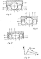
- FIGS. 6 to 13 two further exemplary embodiments for the construction of a keyboard are explained, in which, when the keyboard button 1 is pressed down along a path S, the spring force P exerted by the toroidal core 5 initially increases and then decreases again to lower values when the button is pressed further. This creates a pressure point which, after the maximum range of the force P has been exceeded, forces the keyboard operator to press the key further until it stops.
- FIGS. 6, 7 and 8 Such a pressure point behavior can be achieved with the arrangement according to FIGS. 6, 7 and 8.
- the keyboard button 1 has on the side facing the toroidal core 5 a groove-shaped opening 22 which is laterally delimited by two edges 23.
- the cross section of the groove-shaped opening is shown rectangular in the exemplary embodiment, but it can be of any design and only has to meet the condition that the ring band core can slide into the groove-shaped opening.
- FIG. 7 shows the arrangement according to FIG. 6 after the keyboard button 1 has been pressed down so far that the edges 23 touch the ring band core.
- the deformation of the toroidal core 5 * begins
- Figure 8 shows the arrangement after the toroidal core 13 has slipped into the groove-shaped opening 22.
- FIG. 9 shows a curve K 1 measured in an experimental arrangement according to FIGS. 6 to 8, which represents the force acting on the keyboard button 1 over the path S of the keyboard button 1 when depressed and when released.
- FIGS. 10 to 12 show a similar arrangement with a likewise falling spring force after the maximum has been exceeded, again with corresponding positions of the keyboard button 1.
- the wall of the housing 4 above the center of the ring core 5 has a projection 24 extending inwards towards the ring core which, together with the wall of the housing 4 and the base plate 7, forms a groove-shaped opening 22 which is open towards the ring core 5.
- the difference between static and sliding friction between the ring band core and the projection 24 is used in order to achieve a drop in the spring force after an increase in the force, corresponding to curve K2 in FIG.
- the width of the groove-shaped opening 22 is decisive for the course of the curve. If this width is too large, the toroidal core can jam in the opening so that the frictional force outweighs the spring force and a negative force is required to pull up the keyboard. If the width of the opening is too small, excessive forces or deformations of the toroidal core may be necessary if the maximum value of the force increase is to be exceeded. For each construction, the individual values must therefore be determined experimentally beforehand.
- the deformation of the toroidal core is used both to generate a spring force on the keyboard button and also to determine an electrical signal from the magnetic properties that change during deformation.
- the shape of the hysteresis loop of the material is not directly dependent on the spring force, as was measured in FIGS. 9 and 13. Nevertheless, there may be a wish that both a spring force characteristic according to FIGS. 9 or 13 and a continuous deformation of the toroidal core should be achieved with the path of the keyboard button.
- both the spring characteristic and the magnetic characteristic can be set independently of one another via the path S of the keyboard button.
Landscapes
- Physics & Mathematics (AREA)
- Nonlinear Science (AREA)
- Input From Keyboards Or The Like (AREA)
- Push-Button Switches (AREA)
Applications Claiming Priority (2)
| Application Number | Priority Date | Filing Date | Title |
|---|---|---|---|
| DE3127053 | 1981-07-09 | ||
| DE3127053A DE3127053C2 (de) | 1981-07-09 | 1981-07-09 | Sensortaste zur kontaktlosen Erzeugung eines elektrischen Signals bei Tastendruck |
Publications (2)
| Publication Number | Publication Date |
|---|---|
| EP0069877A1 true EP0069877A1 (fr) | 1983-01-19 |
| EP0069877B1 EP0069877B1 (fr) | 1985-10-09 |
Family
ID=6136460
Family Applications (1)
| Application Number | Title | Priority Date | Filing Date |
|---|---|---|---|
| EP82105363A Expired EP0069877B1 (fr) | 1981-07-09 | 1982-06-18 | Capteur à touche pour engendrer sans contact un signal électrique lors de la pression sur la touche |
Country Status (3)
| Country | Link |
|---|---|
| US (1) | US4507651A (fr) |
| EP (1) | EP0069877B1 (fr) |
| DE (2) | DE3127053C2 (fr) |
Cited By (1)
| Publication number | Priority date | Publication date | Assignee | Title |
|---|---|---|---|---|
| CN110011655A (zh) * | 2019-05-09 | 2019-07-12 | 南京艾驰电子科技有限公司 | 一种无触点微动按键及其实现方法 |
Families Citing this family (6)
| Publication number | Priority date | Publication date | Assignee | Title |
|---|---|---|---|---|
| SE452082B (sv) * | 1986-12-15 | 1987-11-09 | Inter Innovation Ab | Manoverenhet for datakommunikation |
| US5793311A (en) * | 1996-12-27 | 1998-08-11 | Texas Instruments Incorporated | Low profile keyboard |
| TWI270910B (en) * | 2005-12-07 | 2007-01-11 | Inst Information Industry | Electronic switching device using non-interrupt voltage modulation switch |
| US7576948B2 (en) * | 2006-02-23 | 2009-08-18 | Seagate Technology Llc | Magnetic field read sensor based on the extraordinary hall effect |
| US8115745B2 (en) * | 2008-06-19 | 2012-02-14 | Tactile Displays, Llc | Apparatus and method for interactive display with tactile feedback |
| US8217908B2 (en) * | 2008-06-19 | 2012-07-10 | Tactile Displays, Llc | Apparatus and method for interactive display with tactile feedback |
Citations (1)
| Publication number | Priority date | Publication date | Assignee | Title |
|---|---|---|---|---|
| FR2241169A1 (fr) * | 1973-08-15 | 1975-03-14 | Illinois Tool Works |
Family Cites Families (7)
| Publication number | Priority date | Publication date | Assignee | Title |
|---|---|---|---|---|
| US3735058A (en) * | 1971-09-15 | 1973-05-22 | Addmaster Corp | Keyboard printed circuit switch assembly with axially movable coil spring contact and associated key type actuator |
| US3767878A (en) * | 1972-09-21 | 1973-10-23 | Stackpole Component Co | Keyboard switch |
| GB1460021A (en) * | 1973-01-24 | 1976-12-31 | Gen Electric Co Ltd | Electric switches |
| US3920943A (en) * | 1974-03-22 | 1975-11-18 | Magsat Corp | Electrical switch |
| US4028696A (en) * | 1976-01-26 | 1977-06-07 | Illinois Tool Works Inc. | Double depression magnetic keyswitch |
| US4116728B1 (en) * | 1976-09-02 | 1994-05-03 | Gen Electric | Treatment of amorphous magnetic alloys to produce a wide range of magnetic properties |
| US4322973A (en) * | 1980-08-29 | 1982-04-06 | Aisin Seiki Company, Limited | Acceleration and deceleration sensor |
-
1981
- 1981-07-09 DE DE3127053A patent/DE3127053C2/de not_active Expired
-
1982
- 1982-06-18 EP EP82105363A patent/EP0069877B1/fr not_active Expired
- 1982-06-18 DE DE8282105363T patent/DE3266790D1/de not_active Expired
- 1982-07-07 US US06/396,021 patent/US4507651A/en not_active Expired - Lifetime
Patent Citations (1)
| Publication number | Priority date | Publication date | Assignee | Title |
|---|---|---|---|---|
| FR2241169A1 (fr) * | 1973-08-15 | 1975-03-14 | Illinois Tool Works |
Non-Patent Citations (2)
| Title |
|---|
| IEEE TRANSACTIONS ON MAGNETICS, Band MAG-15, Nr. 6, November 1979, Seiten 1806-1808, New York (USA); * |
| SIEMENS FORSCHUNGS- UND ENTWICKLUNGS-BERICHTE, Band 10, Nr. 2, 1981, Seiten 83-90, Würzburg (DE); * |
Cited By (2)
| Publication number | Priority date | Publication date | Assignee | Title |
|---|---|---|---|---|
| CN110011655A (zh) * | 2019-05-09 | 2019-07-12 | 南京艾驰电子科技有限公司 | 一种无触点微动按键及其实现方法 |
| CN110011655B (zh) * | 2019-05-09 | 2023-05-23 | 南京艾驰电子科技有限公司 | 一种无触点微动按键及其实现方法 |
Also Published As
| Publication number | Publication date |
|---|---|
| DE3266790D1 (en) | 1985-11-14 |
| US4507651A (en) | 1985-03-26 |
| EP0069877B1 (fr) | 1985-10-09 |
| DE3127053C2 (de) | 1983-07-21 |
| DE3127053A1 (de) | 1983-01-27 |
Similar Documents
| Publication | Publication Date | Title |
|---|---|---|
| DE2658456C2 (de) | Zweiteiliger Magnet | |
| DE2048428C3 (de) | Induktiver Meß-Umformer | |
| EP0218042B2 (fr) | Commutateur de proximité électronique dépendant d'un champ magnétique | |
| WO1990003037A1 (fr) | Aimant a noyau plongeur et son utilisation comme marteau d'impression dans un dispositif a marteau d'impression | |
| EP0069877B1 (fr) | Capteur à touche pour engendrer sans contact un signal électrique lors de la pression sur la touche | |
| DE10315764B4 (de) | Elektromagnetischer Energiewandler für miniaturisierte Funkschalter | |
| DE2362839A1 (de) | Druckknopf mit mehreren galvanischen kontakten und rueckfuehrung in seine ruhestellung durch eine magnetische vorrichtung | |
| DE69321419T2 (de) | Magnetschalter | |
| DE3689708T2 (de) | Anordnung zur feststellung des funktionierens eines elektromagnetischen betätigers. | |
| DE8205982U1 (de) | Vorrichtung zur umformung eines elektrischen signales in ein pneumatisches drucksignal | |
| DE3244507A1 (de) | Magnetfeldabhaengiger induktiver naeherungsschalter | |
| DE69313348T2 (de) | Verbesserter Zwischenträger für Relais zur Anwendung, insbesondere in Kraftfahrzeugen | |
| DE3152067C2 (de) | Tastvorrichtung mit einem in ihrer Ruhestellung geschlossenen elektrischen Schalter | |
| CH659324A5 (de) | Elektromagnetisch kraftkompensierende waage. | |
| DE102014002030A1 (de) | Haptikerzeugende Vorrichtung, insbesondere für einen elektrischen Schalter und elektrischer Schalter mit einer haptikerzeugenden Vorrichtung | |
| DE1099077B (de) | Kraftuebertragungsvorrichtung mit magnetisch kuppelbaren Teilen | |
| EP1207541A1 (fr) | Microrupteur avec force de contact renforcée | |
| DE112018005434T5 (de) | Solenoidvorrichtung | |
| DE1690100C (de) | Tastatur zur Abgabe von aufeinanderfolgenden Steuerbefehlen | |
| DE69108072T2 (de) | Konische Feder für einen elektrischen Kontakt. | |
| DE2832572B1 (de) | Musikinstrument mit Blasebalg mit von der Bewegung des Blasebalges betaetigter elektro-pneumatischer Steuerschaltvorrichtung | |
| DE2639576C3 (de) | Kontaktfreies Schaltelement | |
| DE1439516C (de) | Elektromagnet ohne Anker mit Anzeige vorrichtung | |
| DE2005138C3 (de) | Elektrischer Kipphebelschalter | |
| DE1512469C3 (de) | Einer Kodierschaltung zugeordnete tastenbetätigte Vorrichtung zur Erzeugung eines elektrischen Impulses |
Legal Events
| Date | Code | Title | Description |
|---|---|---|---|
| PUAI | Public reference made under article 153(3) epc to a published international application that has entered the european phase |
Free format text: ORIGINAL CODE: 0009012 |
|
| AK | Designated contracting states |
Designated state(s): CH DE FR GB IT LI NL SE |
|
| 17P | Request for examination filed |
Effective date: 19830601 |
|
| ITF | It: translation for a ep patent filed | ||
| GRAA | (expected) grant |
Free format text: ORIGINAL CODE: 0009210 |
|
| AK | Designated contracting states |
Designated state(s): CH DE FR GB IT LI NL SE |
|
| REF | Corresponds to: |
Ref document number: 3266790 Country of ref document: DE Date of ref document: 19851114 |
|
| ET | Fr: translation filed | ||
| PLBE | No opposition filed within time limit |
Free format text: ORIGINAL CODE: 0009261 |
|
| STAA | Information on the status of an ep patent application or granted ep patent |
Free format text: STATUS: NO OPPOSITION FILED WITHIN TIME LIMIT |
|
| 26N | No opposition filed | ||
| PGFP | Annual fee paid to national office [announced via postgrant information from national office to epo] |
Ref country code: NL Payment date: 19870630 Year of fee payment: 6 |
|
| PG25 | Lapsed in a contracting state [announced via postgrant information from national office to epo] |
Ref country code: GB Effective date: 19890618 |
|
| PG25 | Lapsed in a contracting state [announced via postgrant information from national office to epo] |
Ref country code: SE Effective date: 19890619 |
|
| PG25 | Lapsed in a contracting state [announced via postgrant information from national office to epo] |
Ref country code: LI Effective date: 19890630 Ref country code: CH Effective date: 19890630 |
|
| PG25 | Lapsed in a contracting state [announced via postgrant information from national office to epo] |
Ref country code: NL Effective date: 19900101 |
|
| GBPC | Gb: european patent ceased through non-payment of renewal fee | ||
| NLV4 | Nl: lapsed or anulled due to non-payment of the annual fee | ||
| PG25 | Lapsed in a contracting state [announced via postgrant information from national office to epo] |
Ref country code: FR Free format text: LAPSE BECAUSE OF NON-PAYMENT OF DUE FEES Effective date: 19900228 |
|
| REG | Reference to a national code |
Ref country code: CH Ref legal event code: PL |
|
| PG25 | Lapsed in a contracting state [announced via postgrant information from national office to epo] |
Ref country code: DE Effective date: 19900301 |
|
| REG | Reference to a national code |
Ref country code: FR Ref legal event code: ST |
|
| EUG | Se: european patent has lapsed |
Ref document number: 82105363.4 Effective date: 19900412 |