EP0069990A1 - Selle pour vehicule a deux roues - Google Patents
Selle pour vehicule a deux roues Download PDFInfo
- Publication number
- EP0069990A1 EP0069990A1 EP82106094A EP82106094A EP0069990A1 EP 0069990 A1 EP0069990 A1 EP 0069990A1 EP 82106094 A EP82106094 A EP 82106094A EP 82106094 A EP82106094 A EP 82106094A EP 0069990 A1 EP0069990 A1 EP 0069990A1
- Authority
- EP
- European Patent Office
- Prior art keywords
- saddle
- connection
- spring
- support body
- openings
- Prior art date
- Legal status (The legal status is an assumption and is not a legal conclusion. Google has not performed a legal analysis and makes no representation as to the accuracy of the status listed.)
- Withdrawn
Links
Images

Classifications
-
- B—PERFORMING OPERATIONS; TRANSPORTING
- B62—LAND VEHICLES FOR TRAVELLING OTHERWISE THAN ON RAILS
- B62J—CYCLE SADDLES OR SEATS; AUXILIARY DEVICES OR ACCESSORIES SPECIALLY ADAPTED TO CYCLES AND NOT OTHERWISE PROVIDED FOR, e.g. ARTICLE CARRIERS OR CYCLE PROTECTORS
- B62J1/00—Saddles or other seats for cycles; Arrangement thereof; Component parts
- B62J1/02—Saddles resiliently mounted on the frame; Equipment therefor, e.g. springs
Definitions
- the invention relates to a saddle for two-wheelers, consisting of a base and an upper part which has a support body provided with padding, which is unsprung to the base at its front end and is connected at its rear end via coil springs.
- the object of the invention is to design a saddle of the type described at the outset in such a way that the preassembled and finished base frame can be connected in a simple manner to the already finished upper part.
- connection of the coil springs to the supporting body is designed as a plug-in connection, in which the spring ends, which essentially run freely in a parallel to the saddle surface, can be inserted into openings in the supporting body and the Front connection between the support body and the base frame is formed as a connection that can also be produced after the rear plug connection has been established.
- the entire underframe including springs can be preassembled and coated or lacquered or galvanically coated and then connected to the upper part in a few simple steps by inserting the free spring ends of the coil springs into the openings on the supporting body and then the underframe with the upper part on front end is connected.
- connection between the underframe and the upper part at the front end can either be made by a rigid rivet connection, and in the event that sensitive padding is provided, rivets can also be used which require machining from one side only, as is the case here is possible with rivets that are used for riveting sheet metal that form a closed cavity, such as this for example in the aircraft industry.
- this front connection between the base frame and the support body is designed to be detachable in the manner of a push button.
- a thickened head is provided on one of the two parts, while the opposite part has an opening with resilient legs which can be pressed apart and which snap behind the head after it has been inserted.
- An advantageous embodiment is that the free ends of the coil springs are designed as a tangent to the spring circumference parallel to the longitudinal axis of the saddle projecting to the rear. As a result, the process of inserting the free spring ends into the openings on the supporting part is particularly simple.
- the plug connection can still be carried out relatively easily.
- the openings for receiving the free spring ends can be provided in shoulders or pins which are connected to the supporting body.
- the Lugs or pins are releasably attached to the support body by means of a snap connection. But it is also possible that the lugs or pins are integrally formed on the support body.
- the coil spring axes are inclined in the direction, preferably by 15 ° with respect to the vertical, in the show the free coil spring ends.
- the coil springs which are attached to the base at an angle of inclination, must be elastically deformed when the base is combined with the upper part in order to get the ends into the openings.
- the coil springs are preloaded, i.e. they are deflected transversely to their longitudinal axis, whereby they sit firmly with their ends in the openings of the lugs or pins on the supporting part of the upper part.
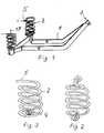
- a base frame 1 is shown, at the rear end of which two coil springs 2 are fastened, while the front end which is pulled upward bears part 3 of a push-button connection to be described in more detail.
- the springs 2, one of which is shown on a larger scale in FIG. 3, are designed as coil springs, in which the lower end of the spring wire is rolled inwards to form an eye 4, through which a rivet which cannot be seen in the drawing is inserted. to connect the spring 2 to the base 1.
- the upper end of the helical spring is designed as a free spring end, this spring end 5 being designed as a tangent to the spring turn, protruding slightly beyond the circumference of the helical spring and, in the assembled state, aligned parallel to the longitudinal axis of the saddle. Since the upper spring end is open, a holder can be inserted in a simple manner for riveting the lower spring end. In the case of helical springs in which the upper end of the spring corresponds to the lower end of the spring according to FIG. 3, such simple riveting is not possible because the counter-holder has to be inserted through the windings. Although this is not necessary in the known spring shown in FIG. 2, in which the spring eyes are bent, an additional amount of work is required for this turning, as already explained at the beginning.
- Fig. 4 the upper part of a saddle is shown, which consists of a support body 6 and a padding 7.
- pins 8 are provided which, as shown in FIG. 5, can be designed as insertion pins which are provided with barbs 9 in order to prevent the pin from being retracted.
- These pins 8, two of which are provided, have openings 10, into which the ends 5 of the coil springs 2 can be inserted.
- An opening 11 is provided at the front end of the support body 6, and a spring 12 is provided on the upper side of the support body 6 in the area of the opening 11 within the padding 7, which is designed in the manner of a hairpin.
- the two legs of this spring snap behind a head 13 of the part 3 arranged on the underframe 1 when this head is pressed through the opening 11.
- the head 13 sits at the end of a rivet 14 which is fastened to the front end of the underframe 1 and, together with spacers 15 and 16, forms part 3 of the push-button connection.
- the helical springs 12 are mounted on the base 1 so that their longitudinal axes 17 are inclined to the rear, which makes it necessary to connect the upper part 6 , 7 to press the coil springs forward with the base frame after inserting the spring ends 5 into the openings 10 in order to close the push-button connection at the front end.
- the coil springs are under prestress, since they are bent about their longitudinal axis during this assembly process, so that the spring ends 5 can no longer slide out of the openings 10.
Landscapes
- Engineering & Computer Science (AREA)
- Mechanical Engineering (AREA)
- Springs (AREA)
- Connection Of Plates (AREA)
Applications Claiming Priority (2)
| Application Number | Priority Date | Filing Date | Title |
|---|---|---|---|
| DE19813127396 DE3127396A1 (de) | 1981-07-10 | 1981-07-10 | Sattel fuer zweiraeder |
| DE3127396 | 1981-07-10 |
Publications (1)
| Publication Number | Publication Date |
|---|---|
| EP0069990A1 true EP0069990A1 (fr) | 1983-01-19 |
Family
ID=6136665
Family Applications (1)
| Application Number | Title | Priority Date | Filing Date |
|---|---|---|---|
| EP82106094A Withdrawn EP0069990A1 (fr) | 1981-07-10 | 1982-07-08 | Selle pour vehicule a deux roues |
Country Status (2)
| Country | Link |
|---|---|
| EP (1) | EP0069990A1 (fr) |
| DE (1) | DE3127396A1 (fr) |
Citations (7)
| Publication number | Priority date | Publication date | Assignee | Title |
|---|---|---|---|---|
| FR562015A (fr) * | 1923-11-02 | |||
| US2262221A (en) * | 1937-06-16 | 1941-11-11 | Giles E Bullock | Saddle construction |
| GB914345A (en) * | 1958-05-14 | 1963-01-02 | Tommaso Nieddu | Improvements relating to saddles for bicycles, motorcycles and the like |
| FR2192524A5 (fr) * | 1972-07-11 | 1974-02-08 | Gallet Jean Fil Ets | |
| DE2353930A1 (de) * | 1972-11-02 | 1974-05-09 | Mertens & Co Kg | Sattel, insbesondere zweiradsattel |
| US3884525A (en) * | 1972-11-10 | 1975-05-20 | Robert H Mesinger | Bicycle seat structure |
| FR2291899A1 (fr) * | 1974-11-25 | 1976-06-18 | Castres Jean Jacques | Perfectionnements apportes aux selles de cycles et motocycles |
-
1981
- 1981-07-10 DE DE19813127396 patent/DE3127396A1/de not_active Withdrawn
-
1982
- 1982-07-08 EP EP82106094A patent/EP0069990A1/fr not_active Withdrawn
Patent Citations (7)
| Publication number | Priority date | Publication date | Assignee | Title |
|---|---|---|---|---|
| FR562015A (fr) * | 1923-11-02 | |||
| US2262221A (en) * | 1937-06-16 | 1941-11-11 | Giles E Bullock | Saddle construction |
| GB914345A (en) * | 1958-05-14 | 1963-01-02 | Tommaso Nieddu | Improvements relating to saddles for bicycles, motorcycles and the like |
| FR2192524A5 (fr) * | 1972-07-11 | 1974-02-08 | Gallet Jean Fil Ets | |
| DE2353930A1 (de) * | 1972-11-02 | 1974-05-09 | Mertens & Co Kg | Sattel, insbesondere zweiradsattel |
| US3884525A (en) * | 1972-11-10 | 1975-05-20 | Robert H Mesinger | Bicycle seat structure |
| FR2291899A1 (fr) * | 1974-11-25 | 1976-06-18 | Castres Jean Jacques | Perfectionnements apportes aux selles de cycles et motocycles |
Also Published As
| Publication number | Publication date |
|---|---|
| DE3127396A1 (de) | 1983-01-27 |
Similar Documents
| Publication | Publication Date | Title |
|---|---|---|
| DE3732674C2 (fr) | ||
| DE4234116C2 (de) | Schwingungsdämpfungseinrichtung | |
| EP1128981A1 (fr) | Siege de vehicule dote d'une liaison a montage rapide | |
| DE2353930C3 (de) | Sattel, insbesondere Zweiradsattel | |
| DE3410389C2 (fr) | ||
| DE2906288C2 (de) | Anbauteil zum Anschluß an eine Wandung, insbesondere Griff oder Armlehne zum Anschluß an ein Karosserieteil eines Kraftfahrzeuges | |
| DE2856621B2 (de) | Ausbildung und Anordnung der Eintreibfeder an einem durch Muskelkraft betriebenen tragbaren Heftwerkzeug | |
| DE3143555A1 (de) | Dachkonstruktion fuer ein fahrzeug | |
| DE3937553C2 (de) | Sitz mit einem Federtragrahmen | |
| DE69006703T2 (de) | Scharnier für eine Sonnenblende eines Kraftfahrzeuges. | |
| DE2441565C3 (de) | Schieber | |
| AT404768B (de) | Relais | |
| DE3228321C2 (fr) | ||
| DE102018008392A1 (de) | Halterung zur Befestigung einer Gepäck-Tragvorrichtung | |
| DE1924879A1 (de) | Wischblatteinheit fuer Windschutzscheiben | |
| EP0583580A2 (fr) | Articulation à chape | |
| DE3127396A1 (de) | Sattel fuer zweiraeder | |
| DE2430346C3 (de) | Skibindung mit Klemmbügel | |
| DE2260252A1 (de) | Vorrichtung zur befestigung von gangschaltungen unterschiedlicher bauart an einem fahrradrahmen | |
| EP0686102A1 (fr) | Commutateur fixe a la colonne de direction de vehicules a moteur | |
| DE2725422C2 (de) | Batterieklemme | |
| DE2413620A1 (de) | Zwischenstueck zum befestigen eines wischarms an einer wischerwelle | |
| DE2249765C3 (de) | Befestigung einer Drahtfeder an einem Rahmen, Insbesondere für Fahrzeugsitze | |
| DE69201518T2 (de) | Biegsames Organ für Kraftübertragung. | |
| DE805844C (de) | Fahrradrahmen-Muffen und Verfahren zu ihrer Herstellung |
Legal Events
| Date | Code | Title | Description |
|---|---|---|---|
| PUAI | Public reference made under article 153(3) epc to a published international application that has entered the european phase |
Free format text: ORIGINAL CODE: 0009012 |
|
| AK | Designated contracting states |
Designated state(s): BE FR GB IT NL |
|
| STAA | Information on the status of an ep patent application or granted ep patent |
Free format text: STATUS: THE APPLICATION IS DEEMED TO BE WITHDRAWN |
|
| 18D | Application deemed to be withdrawn |
Effective date: 19831229 |
|
| RIN1 | Information on inventor provided before grant (corrected) |
Inventor name: KAALVERINK, GERRY H. |