EP0070073A1 - Zuführeinrichtung für automatische Drehbänke und deren Herstellung - Google Patents
Zuführeinrichtung für automatische Drehbänke und deren Herstellung Download PDFInfo
- Publication number
- EP0070073A1 EP0070073A1 EP82200858A EP82200858A EP0070073A1 EP 0070073 A1 EP0070073 A1 EP 0070073A1 EP 82200858 A EP82200858 A EP 82200858A EP 82200858 A EP82200858 A EP 82200858A EP 0070073 A1 EP0070073 A1 EP 0070073A1
- Authority
- EP
- European Patent Office
- Prior art keywords
- marginal
- profile
- tubes
- tubular
- profiles
- Prior art date
- Legal status (The legal status is an assumption and is not a legal conclusion. Google has not performed a legal analysis and makes no representation as to the accuracy of the status listed.)
- Granted
Links
- 238000004519 manufacturing process Methods 0.000 title description 12
- 239000000463 material Substances 0.000 claims description 15
- 239000011248 coating agent Substances 0.000 claims description 11
- 238000000576 coating method Methods 0.000 claims description 11
- 229920002994 synthetic fiber Polymers 0.000 claims description 4
- 230000000295 complement effect Effects 0.000 claims description 2
- 238000009413 insulation Methods 0.000 claims description 2
- 238000002955 isolation Methods 0.000 claims 1
- 230000002093 peripheral effect Effects 0.000 abstract description 2
- 239000003921 oil Substances 0.000 description 27
- 238000010276 construction Methods 0.000 description 14
- 239000002184 metal Substances 0.000 description 5
- 238000005452 bending Methods 0.000 description 3
- 239000000470 constituent Substances 0.000 description 3
- 238000009826 distribution Methods 0.000 description 3
- 238000000034 method Methods 0.000 description 3
- 208000031968 Cadaver Diseases 0.000 description 2
- 230000000694 effects Effects 0.000 description 2
- 238000007373 indentation Methods 0.000 description 2
- 238000005304 joining Methods 0.000 description 2
- 230000004048 modification Effects 0.000 description 2
- 238000012986 modification Methods 0.000 description 2
- 238000011084 recovery Methods 0.000 description 2
- 230000003014 reinforcing effect Effects 0.000 description 2
- 238000010079 rubber tapping Methods 0.000 description 2
- 239000007787 solid Substances 0.000 description 2
- 238000004026 adhesive bonding Methods 0.000 description 1
- 210000004027 cell Anatomy 0.000 description 1
- 230000001419 dependent effect Effects 0.000 description 1
- 238000006073 displacement reaction Methods 0.000 description 1
- 238000001125 extrusion Methods 0.000 description 1
- 230000005484 gravity Effects 0.000 description 1
- 238000009434 installation Methods 0.000 description 1
- 230000001788 irregular Effects 0.000 description 1
- 239000007788 liquid Substances 0.000 description 1
- 239000012778 molding material Substances 0.000 description 1
- 238000000465 moulding Methods 0.000 description 1
- 239000000346 nonvolatile oil Substances 0.000 description 1
- 230000001105 regulatory effect Effects 0.000 description 1
- 230000000284 resting effect Effects 0.000 description 1
- 238000007789 sealing Methods 0.000 description 1
- 238000005245 sintering Methods 0.000 description 1
- 125000006850 spacer group Chemical group 0.000 description 1
- 238000003466 welding Methods 0.000 description 1
Images


Classifications
-
- B—PERFORMING OPERATIONS; TRANSPORTING
- B23—MACHINE TOOLS; METAL-WORKING NOT OTHERWISE PROVIDED FOR
- B23B—TURNING; BORING
- B23B13/00—Arrangements for automatically conveying or chucking or guiding stock
- B23B13/12—Accessories, e.g. stops, grippers
- B23B13/123—Grippers, pushers or guiding tubes
-
- Y—GENERAL TAGGING OF NEW TECHNOLOGICAL DEVELOPMENTS; GENERAL TAGGING OF CROSS-SECTIONAL TECHNOLOGIES SPANNING OVER SEVERAL SECTIONS OF THE IPC; TECHNICAL SUBJECTS COVERED BY FORMER USPC CROSS-REFERENCE ART COLLECTIONS [XRACs] AND DIGESTS
- Y10—TECHNICAL SUBJECTS COVERED BY FORMER USPC
- Y10T—TECHNICAL SUBJECTS COVERED BY FORMER US CLASSIFICATION
- Y10T82/00—Turning
- Y10T82/25—Lathe
- Y10T82/2514—Lathe with work feeder or remover
- Y10T82/2516—Magazine type
- Y10T82/2518—Bar feeder
Definitions
- the present invention relates to a refueling device for an automatic lathe having a plurality of bar-guide tubular spaces of different diameters. It also relates to a method of manufacturing the same.
- a performance that such a refueling device must achieve, at least in an approximate manner, is that the axes of the various inner tubes are indeed parallel to the axis of the device, that is to say to the axis of the outer tube or mantle, and that in addition the axes of the inner tubes are all placed at equal distance from the axis of the outer tube, or axis of the device.
- these two performances are approximately achieved by the implementation expensive tooling specially designed to hold the different tubes in place relative to each other when a coating mass still in the liquid state is poured into the tube.
- the object of the present invention is to provide a supply device of the general type in question which solves the previously mentioned problems known from the prior art, that is to say which allows a simplification and a reduction in the cost of manufacture and which allows to better ensure the geometrical conditions, that is to say mainly the condition of concentricity, of the arrangement of the guide-bar conduits in the overall cylindrical arrangement.
- This aim is therefore at the same time to provide a supply which is both less expensive to manufacture and more precise in its dimensions, that is to say more convenient to use.
- the invention amounts to reversing the constitution of a device of the type in question, somewhat similar to a barrel. Barrel devices were formed, but which differed from the device in question by the fact that all the barrel tubes had the same diameter, which simplified the construction and allowed great accuracy without great difficulty, by taking a series of tubes and by joining them with poles, spacers, discs, etc., so as to form a kind of cage.
- tubes or liners in the tubular spaces, to adequately establish the tubular spaces used for guiding the bar, but these tubes, if they exist, are put in place after creation of the structure , in voids adequately formed therein, and they are not used to create the structure.
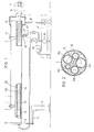
- Figs. 1 and 2 represent a known supply device, of the LNS HYS (Superhydrobar) type.
- a outer tube or mantle 1 which is movable and indexable in rotation, under manual control, is held in a rear bearing 2 and a front bearing 3, the rear bearing resting on a fixed support 4 while the front bearing 3 s' presses against a fixed support or similar element not shown.
- Inside the mantle or outer tube 1 is located, as shown in fig. 2, a plurality of guide tubes, or inner tubes 5A, 5B, 5C, 5D and 5E, these guide tubes being coated in a molding material, or coating mass, 6.
- the axes of the inner tubes 5A to 5E are all at the same distance from the main axis of the device, that is to say from the axis of the outer tube or mantle 1, so that, as required, one or the other of these guide tubes can be brought into axial alignment with the headstock pin 7 of an automatic lathe.
- the positioning of the refueling device on the supports is such that the inner tube, or bar guide tube, which is in the low position inside the mantle 1 is in alignment with the spindle of the lathe doll.
- another arrangement could be adopted depending on the supports.
- a bar of material to be machined 14 is located inside the bar guide tube 5A, in alignment with the spindle of the lathe headstock; when a bar has been completely consumed and a new bar must be introduced into the tube, the front part of the refueling device can slide laterally on the supports, in a manner not shown.
- the arches of the bearings 2 and 3 are suitably arranged so that a screw-lever 11 allows adequate fixing of the outer tube or mantle 1, on the supports, at the rear of the lathe.
- a screw-lever 11 allows adequate fixing of the outer tube or mantle 1, on the supports, at the rear of the lathe.
- the bar guide tube inside the bar guide tube (in fig. 1, the bar guide tube 5A) the bar of material to be machined 14 is pushed by a stroller 13 at the rear of which is a piston 12.
- Each tube bar guide 5A to 5D contains a piston adequate diameter, actuating a stroller.
- Pressurized oil is supplied to the rear of the bar guide tube, through an opening in a rear cover 8 which closes the device.
- An oil supply and recovery arrangement 16 to 19 applies an oil pressure in the bar guide tube at the rear of the piston 12, so as to push the latter forward to advance the bar.
- the oil supply and recovery arrangement comprises, in addition to the oil collection cap 15, the return duct 16, and the tank 17, a pump 18 and an arrangement 19 of piping and regulating members which ensure the supply of oil, in the desired quantity and at the desired pressure, to the rear of the bar guide tube 5A.
- the cover 8 is prevented from rotating by an arm 9 and a bar 10 fixed to the rear support 4.
- a line 22 transmits the oil pressure to a pressure detector 21 actuating a contact 23.
- the oil pressure at the front of the piston is lower than the oil pressure at the rear of the piston, and, when the piston 12 crosses the place where is the pressure tapping channel 22, the pressure detector 21 notices an increase in pressure, and consequently actuates the switch 23.
- the length of the stroller 13, as well as the position of the pressure tapping duct 22, taking into account of the distance between the front of the device and the clamp of the spindle of the lathe, are established in such a way that the sensor 21 actuates the contact 23 when the bar of material to be machined 14 is consumed to the maximum, the stroller 13 then finding in the lathe doll.
- An inversion of the oil pressure, that is to say the presence of an oil depression, at the rear of the piston 12 causes the piston and the stroller to move back to the bottom of the bar guide tube, while the last piece of material remains temporarily in the lathe clamp to be extracted therefrom using suitable means while the bar guide tube is recharged with a new bar of material to be machined.
- the refueling device of the superhydrobar type comprises a plurality of bar guide tubes which can, as desired according to the desire of the user, be brought into alignment with the spindle of the lathe.
- the manufacture of the cylinder comprising the outer tube or mantle 1 and the inner tubes or bar guide tubes 5A-5E, with interposition of the mass of tap 6, poses a certain number of problems taking into account in particular the fact that the different guide bar tubes are of different diameters. It is important that they are all kept in a position such that the distance between their axis and the axis of the device is equal for all the tubes. Furthermore, the angular position of the inner tubes is important because the exact position in alignment with the headstock must be able to be determined with precision by indexing the outer tube. In practice, the manufacture of the device as illustrated in FIGS. 1 and 2 is expensive, complicated and still allows only relative accuracy in the positioning of the bar guide tubes inside the outer tube.
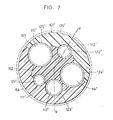
- Figs. 3 and 4 show in section the device by which the set of five bar guide conduits is established inside a cylindrical assembly, in a manner suitable for constituting a tanker.
- the elongated cylindrical body 101, 101 'constituting the tanker is formed of a central section 102, 102', around which are placed several (typically two possiblemen L but also more than two) edge profiles 103, 103 'and 104, 104' (signs with premiums refer to fig. 3 and those without premiums refer to fig. 4).
- profiles made of a material which is sufficiently hard for the very surface of the longitudinal grooves to constitute the wall of the bar-guide duct.
- it is not necessary to provide for the engagement of metal tubes in the conduits formed by the union of two notches, one of the central profile and the other of a marginal profile it will however be advisable to hold the two marginal profiles together, which can be done either by engaging the three assembled profiles in an outer tube 126 '(shown in dotted lines in FIG. 3, because of its optional nature), or by using other means (not shown) for fixing the profiles to each other (gluing, screwing, welding, assembly using external flanges, etc.).
- metal guide tubes in the form of jackets, respectively 121 ', 122', 123 ', 124', and 125 ', in the guide conduits 111', 112 ', 113', 114 'and 115 ', (the tubes or sleeves 121' to 125 'are shown in dotted lines in fig. 3, taking into account their optional nature).
- the conduits 111'-115 'formed by the very surfaces of the longitudinal grooves can constitute the guide bar conduits themselves, it may be preferable that the wall of these conduits comprise as few longitudinal junction lines as possible between two profiles. This is the reason why, in fig.
- the two junctions between the marginal sections 103 and 104 are made at the location of the two largest conduits, respectively 114 and 115.
- the marginal sections can therefore have a slightly less complicated shape, on the other hand, we see that the larger ducts 114 and 115 both have part of their wall in the area of the central section 102, the other part in the area of a marginal section 103 and the last part in the area on the other marginal profile, 104. This does not however have any consequence since all the conduits are provided with liners, respectively 121, 122, 123, 124, 125, for the conduits 111, 112, 113, 114, 115.
- the outer tube 126 has also been shown, it being understood that it could possibly be dispensed with, the outer surface of the profiles being able to provide the desired support. In such a case, it would be possible to have an external surface which is not circular, but polygonal, making it easier to index the device.
- plastic profiles have been provided, requiring the presence of inner liners or tubes, and the outer tube has also been drawn in solid lines, although its presence is optional. If the profiles were hard enough, we could also do without 121-125 shirts.
- a rotary distributor or collector 127 which connects a central duct 128 selectively with each of the bar guide conduits of different diameters 111 to 115.
- the different inner tubes or liners 121 to 125 are all provided with a bore (121a-125a) opposite each of which the central section comprises a radial duct respectively 131-135.
- the dis rotary tributor 127 is mounted in a portion close to the end of the device, in a central cavity provided for this purpose.
- This rotary distributor itself comprises a radial duct 137 which, depending on the position of the rotary distributor 127 relative to the entire device, comes into correspondence with one or the other of the five radial ducts 131 to 135.
- the axial central duct 128 can be selectively connected to each of the bar guide ducts 111 to 125.
- FIG. 5 illustrates, moreover, more precisely the arrangement of this central distributor.
- fig. 5 is a sectional view along the line V-V traced in FIGS. 3, 4 and 7,
- the central distributor 127 has a slightly conical shape, being engaged in an equally conical cavity 138, formed in the front end of the device.
- the distributor 127 is therefore in fact a manifold, its role being to transmit the oil pressure prevailing at the front of the bar-guide tube used to actuate, when the time comes, a sensor similar to the sensor 21 in FIG. 1.
- the tightness between the mass of the central profile 102 and the manifold distributor 127 is ensured by the taper of the latter and of the housing. 138 where he is engaged.
- the central axial duct 128 of the distributor 127 is provided, towards the outside, with a thread 141 for the connection of an oil pressure conduction tube.
- a clamping ring 140 is screwed into a thread inside an opening of the front cheek 139, this ring 140 makes it possible to adjust the tightening of the conical piece constituting the distributor 127 in the cavity 138.
- the duct radial 137 of the distributor 127 in connection with the axial duct 128, is in alignment with the radial duct 133 formed in the central section, the tube 123 having at this point a bore 123a, so that the oil conduction is established from inside the tube 123, via the conduits 133 and 137, as far as the central conduit 128.
- the threaded sleeve 140 allows, if necessary, to block its positioning to avoid any risk inadvertent movement, at the same time as for sealing using the conical surfaces present. Due to the possible slight axial displacement of the rotary part 127, the radial duct 137 of the latter will advantageously be somewhat wider than the radial duct 133 formed in the central section.
- the radial duct 132 in connection with the interior of the bar-guide tube 122 via the bore 122a formed therein, reaches the peripheral surface of the rotating part 127, but is blocked at this place, so that no connection exists between the central duct 128 and the bar guide duct 112 delimited by the bar guide tube 122.
- the conical rotating part 127 sealingly plugs the four non-selected radial ducts , 131, 132, 134 and 135 (see fig. 4).
- the cheek 139 has, in addition to the central threaded hole necessary for the arrangement of dis central tribution, five holes which are in alignment with the bar guide tubes, two of these, 142 and 143, being visible in FIG. 5.
- the device comprises a rotary distributor arrangement similar to that which has just been considered but serving for the entry of the oil and its distribution in one, selected, of the bar-guide tubes.
- the reference signs which designate the elements of the rear rotary distribution arrangement are the same as those which designate the homologous elements of the front distribution arrangement, the members of the rear arrangement however being provided with '.
- the functioning and the constitution are identical, it is not necessary to return to it here.
- the front rotary arrangement is advantageously deeper than the rear rotary arrangement, since the radial pressure sensing conduits must open out towards the front at a distance from the end of the tube greater than the distance from the rear end of the tube at which the homologous radial conduits of the rear arrangement must open.
- the rear arrangement for supplying oil will advantageously include ducts wider than the front arrangement which must only transmit an oil pressure value.
- each bar guide duct 146 for the bar guide duct 112 and 150 for the bar guide duct 113.
- a section through the plug 150 is shown in FIG. 6. It is understood that the two plugs 146 and 150 include a solid rear part, surrounded by a seal, respectively 147 and 151. Next, these plugs include a circular groove 146c, 150c, extended by longitudinal recesses 146b , 150b. In line with these longitudinal extensions, the plug part is split by four radial radial slots 146a and 150a, so that its front part is separated into four sectors capable of moving away from one another.
- the plug part comprises an axial hole through which is engaged a screw, respectively 149 and 153, this screw being screwed on the other side in a conical nut, respectively 148 and 152, which engages in a conical recess formed in the right of the four sectors likely to deviate from one another from the plug part 146 or 150. It is easily understood that by screwing the screw 149 or 153 in the conical nut 148 or 152, these parts which come to rest against the inner wall of the tube and firmly fix the stopper piece in the tube, while leaving an oil passage between the circular groove 146c, 150c, and the bar guide duct 112, 113, via axial recesses 146b, 150b of the plug parts 146 and 150.
- the two largest bar guide tubes, 124 and 125 are held between three sections of profiles and could easily be installed laterally. It would suffice with an unimportant arrangement of the edges which are present on both sides of the longitudinal grooves of the marginal sections, at the places where the conduits 111, 112 and 113 are formed, to easily reach 123 a mounting possibility in which the tubes 121 to / would be introduced laterally into the grooves. The slight indentation existing at the place of these edges would create a very small vacuum in the available which would have no consequence whatsoever. With the embodiment of fig.
- the assembly would consist in first of all placing the two tubes 121 and 123 in the marginal profile 104, then in connecting the two larger tubes 124 and 125 to the central profile, in the relative grooves thereof , then put the central profile with the tubes 124 and 125 against the marginal profile 104 with the tubes 121 and 123, then place the tube 122 in the notch of the central profile and finally put the marginal profile 103 in place.
- careful geometric study of fig. 4 shows that this would be possible with only very small indentations at the location of the lips of the grooves having an arcuate profile exceeding 180 ° in the marginal profiles, generally in the form of shells.
- no profile groove has its arcuate profile established over 180 °.
- the larger tubes 124 'and 125' have three profile portions all significantly less than 180 ° , and the smaller tubes, 121 ', 122', 123 ', have two portions which are just 180 °.
- the profile surface portion in which the notches intended for the tubes 121 ′ and 123 ′ open must be a straight line passing through the two centers of the respective tubular conduits.
- the surface portion in which the notches for the tube 122 ′ are formed must also be a straight line, parallel to that which has just been mentioned, and the joining lines between the two marginal sections 163 and 164 need not necessarily be also parallel to these straight lines, but they must end at the tubular conduits where a straight line with this orientation ends and passing through the center of the respective tubular conduit. Under these conditions, not only can the five tubes be placed transversely, i.e. they do not need to be threaded at the end, but in addition there is no handicap for the junction of different profiles.
- the tubes of larger diameters, 125 'and 124' must first be linked to the central profile 162, then we see that the other two profiles, 163 and 164, can be put in place like the cover of a box , in no place will this installation be hindered by interference with a tube.
- the three smaller tubes 121 ′, 122 1 and 123 ′ can be placed at will first in the longitudinal groove of the central profile or in the longitudinal groove of the marginal profile, assembly is done in the same way.
- the outer surface is not cylindrical, however, for reasons of convenience of use, a device of this type having a cylindrical outer surface seems to be preferable. A regular or irregular polygon drawing is not however excluded, the positioning accuracy should then be determined with respect to the planes of the sides of the polygon and no longer with respect to a center.
- the threading of the various elements from the end of the tubes can be improved from this point of view by providing that all or part of the profiles are in several sections.
- the lines 160 show that the total sections of profiles could be divided into several small sections, these being able moreover to be contiguous or on the contrary to leave axial spaces between them.
- the dashed lines 160 of FIG. 5 represent junctions between two successive partial sections, in the other case these lines represent section limits, between which would be an empty space.
- the lines in dotted lines 161 and 161 ′ show a way which could be advantageous of having relatively short sections of profile providing together the total length.
- liners or tubes in the tubular conduits does not only have the effect of reinforcing the rigidity of the material and reinforcing the resistance to wear in the case where the profiles are made of plastic material and these
- the inner tubes are also intended to allow exact adjustment of the desired diameter of the guide bar tube. Depending on the case, it is possible to put in place a tube or jacket of a greater or lesser diameter, with the same outside diameter. It would even be possible to make these tubes interchangeable with the user, with a type of construction of the "meccano" type.
- the different internal tube diameters can of course also be determined during production, according to the wishes of the customer when ordering.
- outer tube or mantle can become quite superfluous in the case where there is only a marginal profile, of annular shape. It is a purely technological question to know if it is advantageous or not to put an external tube in this case, on the other hand, the external tube is useful in the case where one has at least two marginal sections. This outer tube could however be replaced by rings, present only from far to far, or by other means of fixing, for example with screws and bolts, between the two marginal sections.
Landscapes
- Engineering & Computer Science (AREA)
- Mechanical Engineering (AREA)
- Turning (AREA)
- Feeding Of Workpieces (AREA)
Priority Applications (1)
| Application Number | Priority Date | Filing Date | Title |
|---|---|---|---|
| AT82200858T ATE8971T1 (de) | 1981-07-15 | 1982-07-09 | Zufuehreinrichtung fuer automatische drehbaenke und deren herstellung. |
Applications Claiming Priority (2)
| Application Number | Priority Date | Filing Date | Title |
|---|---|---|---|
| CH465081A CH641386A5 (fr) | 1981-07-15 | 1981-07-15 | Dispositif ravitailleur pour tour automatique et procede de fabrication de celui-ci. |
| CH4650/81 | 1981-07-15 |
Publications (2)
| Publication Number | Publication Date |
|---|---|
| EP0070073A1 true EP0070073A1 (de) | 1983-01-19 |
| EP0070073B1 EP0070073B1 (de) | 1984-08-15 |
Family
ID=4280080
Family Applications (1)
| Application Number | Title | Priority Date | Filing Date |
|---|---|---|---|
| EP82200858A Expired EP0070073B1 (de) | 1981-07-15 | 1982-07-09 | Zuführeinrichtung für automatische Drehbänke und deren Herstellung |
Country Status (8)
| Country | Link |
|---|---|
| US (1) | US4577536A (de) |
| EP (1) | EP0070073B1 (de) |
| JP (1) | JPS5815603A (de) |
| AT (1) | ATE8971T1 (de) |
| AU (1) | AU555557B2 (de) |
| CH (1) | CH641386A5 (de) |
| DE (1) | DE3260584D1 (de) |
| ZA (1) | ZA824939B (de) |
Cited By (2)
| Publication number | Priority date | Publication date | Assignee | Title |
|---|---|---|---|---|
| EP0297047A3 (en) * | 1987-06-24 | 1990-08-01 | Sameca Sa | Guide-bar device for automatic lathe and method of fabrication thereof |
| EP3330023A1 (de) * | 2016-11-30 | 2018-06-06 | LNS Management SA | Aufgeformtes fahrgestell für stangenlader |
Families Citing this family (18)
| Publication number | Priority date | Publication date | Assignee | Title |
|---|---|---|---|---|
| JPS6119649U (ja) * | 1984-07-11 | 1986-02-04 | ダイハツ工業株式会社 | シリンダヘツドにおける弁間亀裂の防止装置 |
| DE3476032D1 (en) * | 1984-11-01 | 1989-02-16 | Sameca Sa | Bar guiding device for a multiple-spindle lathe |
| US4676482A (en) * | 1986-04-28 | 1987-06-30 | Rexnord Inc. | Valve seat insert |
| IT1220393B (it) * | 1988-06-03 | 1990-06-15 | Iemca Ind Elettr Complessi Aut | Dispositivo di guida a canali multipli per un caricatore di barre per macchine utensili automatiche |
| DE8814860U1 (de) * | 1988-11-29 | 1989-02-16 | Wilhelm Hainbuch GmbH u. Co Präzisions-Spannwerkzeugfabrik, 7142 Marbach | Zuführvorrichtung für die Dämpfungsflüssigkeit in Führungsrohren bei Mehrspindel-Drehmaschinen und dgl. |
| DE3926841A1 (de) * | 1989-08-14 | 1991-02-21 | Hainbuch Praez Spannwerkzeug | Fuehrungsvorrichtung fuer stangenfoermige werkstuecke von drehmaschinen |
| DE3927532A1 (de) * | 1989-08-21 | 1991-02-28 | Hainbuch Praez Spannwerkzeug | Zufuehrvorrichtung fuer die daempfungsfluessigkeit in fuehrungsrohren bei mehrspindel-drehmaschinen und dergl. |
| DE4428352A1 (de) * | 1993-08-17 | 1995-02-23 | Nat Acme Co | Verfahren und Vorrichtung zum Zuführen von Stangenmaterial |
| JP3208325B2 (ja) * | 1996-06-18 | 2001-09-10 | 株式会社育良精機製作所 | 棒材供給機 |
| JP4137403B2 (ja) | 2001-05-01 | 2008-08-20 | 富士フイルム株式会社 | 記録材料及び画像形成方法 |
| JP2007072192A (ja) | 2005-09-07 | 2007-03-22 | Fujifilm Corp | 光記録媒体及びその製造方法 |
| US20080041200A1 (en) * | 2006-02-22 | 2008-02-21 | Kneebusch William C | Method and apparatus for feeding bars into a cutting lathe |
| JP4874854B2 (ja) | 2007-04-10 | 2012-02-15 | 富士フイルム株式会社 | ホログラフィック記録用組成物およびホログラフィック記録媒体 |
| JP4918393B2 (ja) | 2007-04-19 | 2012-04-18 | 富士フイルム株式会社 | 光記録用組成物およびホログラフィック記録媒体 |
| JP2008304807A (ja) | 2007-06-11 | 2008-12-18 | Fujifilm Corp | 光記録用組成物、ホログラフィック記録媒体および情報記録再生方法 |
| JP2009048066A (ja) | 2007-08-22 | 2009-03-05 | Fujifilm Corp | ホログラフィック記録媒体およびホログラフィック記録装置 |
| US20090142671A1 (en) | 2007-11-30 | 2009-06-04 | Fujifilm Corporation | Optical recording composition and holographic recording medium |
| US9238556B2 (en) | 2011-01-18 | 2016-01-19 | Leoni-Kabel Holding Gmbh | Apparatus for the automated feed of connecting elements to a processing unit and feed hose for the connecting elements |
Citations (7)
| Publication number | Priority date | Publication date | Assignee | Title |
|---|---|---|---|---|
| GB476601A (en) * | 1936-06-12 | 1937-12-13 | Standard Telephones Cables Ltd | Improved guide tube for supporting the stock bar in turning lathes and like machine tools |
| GB551952A (en) * | 1941-09-15 | 1943-03-17 | Esca William Puckert | Improvements in and relating to stock feed mechanism for lathes or other machine tools |
| US3890860A (en) * | 1973-05-21 | 1975-06-24 | Dayco Corp | Silencer and support means for a metal workpiece during machining thereof |
| FR2298254A7 (fr) * | 1975-01-14 | 1976-08-13 | Iemca Spa | Guide pour pourvoyeurs de barres sur machines-outils |
| CH585601A5 (en) * | 1974-10-24 | 1977-03-15 | Juillerat Maurice | Sound-insulating bar guide for machine loader - with casting resin holding apart tubes for bars |
| GB2000702A (en) * | 1977-07-11 | 1979-01-17 | Lns Vente Fab Decolletage | Fluid pressure-controlled barfeed apparatus for automatic lathes |
| EP0026042A1 (de) * | 1979-09-03 | 1981-04-01 | EMI Limited | Zufuhrvorrichtung für Stangen |
Family Cites Families (15)
| Publication number | Priority date | Publication date | Assignee | Title |
|---|---|---|---|---|
| BE567554A (de) * | ||||
| US1020460A (en) * | 1911-03-21 | 1912-03-19 | Nat Acme Mfg Co | Reel for metal-working machines. |
| US2471209A (en) * | 1944-04-18 | 1949-05-24 | Gazdik Laszlo | Protector for pipes |
| US2718302A (en) * | 1952-05-03 | 1955-09-20 | Capaldi Gennaro | Package |
| US3206020A (en) * | 1963-04-09 | 1965-09-14 | Du Pont | Multiple container package |
| AU425908B2 (en) * | 1968-04-10 | 1972-07-10 | Rast Products Pty. Ltd | Improvements in and relating tothe bar feed tubes of lathes |
| CH490141A (de) * | 1968-04-19 | 1970-05-15 | Mach Andre Bechler S A Fab De | Vorrichtung an Langdrehautomat für das Vorschieben von Stangenmaterial |
| US3693810A (en) * | 1971-01-20 | 1972-09-26 | Index Werke Kg Hahn & Tessky | Apparatus for feeding bars or the like in machine tools |
| DE2144190C3 (de) * | 1971-09-03 | 1974-03-14 | Index-Werke Kg Hahn & Tessky, 7300 Esslingen | Stangennachschubeinrichtung für Werkzeugmaschinen, insbesondere Drehautomaten |
| JPS5249577B2 (de) * | 1972-06-20 | 1977-12-17 | ||
| US3910476A (en) * | 1974-04-30 | 1975-10-07 | Chester S Zajac | Keyed pusher tube and collet assembly |
| ES213217Y (es) * | 1975-06-17 | 1976-11-16 | Alecoop, S. Coop. | Disposicion perfeccionada en alimentadores de barras. |
| US4037733A (en) * | 1975-07-29 | 1977-07-26 | Hagenuk Vormals Neufeldt And Kuhnke G.M.B.H. | Bar holder arrangement for bar stock material to be fed to a machine tool |
| US4099617A (en) * | 1977-02-17 | 1978-07-11 | Seattle Box Co. | Shipping bundle for numerous pipe lengths |
| GB2033264B (en) * | 1978-10-05 | 1982-11-17 | Cucchi Pietro Sdf | Feeder apparatus in association with a multi-mandrel lathe and an automatic magazine for the feeder |
-
1981
- 1981-07-15 CH CH465081A patent/CH641386A5/fr not_active IP Right Cessation
-
1982
- 1982-07-08 AU AU85742/82A patent/AU555557B2/en not_active Ceased
- 1982-07-09 AT AT82200858T patent/ATE8971T1/de not_active IP Right Cessation
- 1982-07-09 EP EP82200858A patent/EP0070073B1/de not_active Expired
- 1982-07-09 DE DE8282200858T patent/DE3260584D1/de not_active Expired
- 1982-07-12 ZA ZA824939A patent/ZA824939B/xx unknown
- 1982-07-15 JP JP57122263A patent/JPS5815603A/ja active Granted
-
1984
- 1984-11-30 US US06/676,230 patent/US4577536A/en not_active Expired - Lifetime
Patent Citations (7)
| Publication number | Priority date | Publication date | Assignee | Title |
|---|---|---|---|---|
| GB476601A (en) * | 1936-06-12 | 1937-12-13 | Standard Telephones Cables Ltd | Improved guide tube for supporting the stock bar in turning lathes and like machine tools |
| GB551952A (en) * | 1941-09-15 | 1943-03-17 | Esca William Puckert | Improvements in and relating to stock feed mechanism for lathes or other machine tools |
| US3890860A (en) * | 1973-05-21 | 1975-06-24 | Dayco Corp | Silencer and support means for a metal workpiece during machining thereof |
| CH585601A5 (en) * | 1974-10-24 | 1977-03-15 | Juillerat Maurice | Sound-insulating bar guide for machine loader - with casting resin holding apart tubes for bars |
| FR2298254A7 (fr) * | 1975-01-14 | 1976-08-13 | Iemca Spa | Guide pour pourvoyeurs de barres sur machines-outils |
| GB2000702A (en) * | 1977-07-11 | 1979-01-17 | Lns Vente Fab Decolletage | Fluid pressure-controlled barfeed apparatus for automatic lathes |
| EP0026042A1 (de) * | 1979-09-03 | 1981-04-01 | EMI Limited | Zufuhrvorrichtung für Stangen |
Cited By (5)
| Publication number | Priority date | Publication date | Assignee | Title |
|---|---|---|---|---|
| EP0297047A3 (en) * | 1987-06-24 | 1990-08-01 | Sameca Sa | Guide-bar device for automatic lathe and method of fabrication thereof |
| US5048383A (en) * | 1987-06-24 | 1991-09-17 | Sameca Sa | Guide-bar device for automatic lathe and method of fabrication thereof |
| US5146819A (en) * | 1987-06-24 | 1992-09-15 | Sameca Sa | Guide-bar device for automatic lathe and method of fabrication thereof |
| EP3330023A1 (de) * | 2016-11-30 | 2018-06-06 | LNS Management SA | Aufgeformtes fahrgestell für stangenlader |
| US11104046B2 (en) | 2016-11-30 | 2021-08-31 | Lns Management Sa | Overmolded body for bar feeder |
Also Published As
| Publication number | Publication date |
|---|---|
| ZA824939B (en) | 1983-05-25 |
| US4577536A (en) | 1986-03-25 |
| DE3260584D1 (en) | 1984-09-20 |
| CH641386A5 (fr) | 1984-02-29 |
| ATE8971T1 (de) | 1984-09-15 |
| AU8574282A (en) | 1983-01-20 |
| JPS5815603A (ja) | 1983-01-29 |
| JPS6243803B2 (de) | 1987-09-17 |
| EP0070073B1 (de) | 1984-08-15 |
| AU555557B2 (en) | 1986-10-02 |
Similar Documents
| Publication | Publication Date | Title |
|---|---|---|
| EP0070073B1 (de) | Zuführeinrichtung für automatische Drehbänke und deren Herstellung | |
| EP2168703B1 (de) | Werkzeugträger mit Axialverstellung | |
| CH657794A5 (fr) | Bloc-palier, ravitailleur, notamment pour tour automatique, comprenant de tels blocs-paliers, utilisation de ce bloc-palier. | |
| EP2217423A1 (de) | Spannung einer roll- oder wicklungsvorrichtung | |
| EP2592500A1 (de) | Armbanduhrengehäuse, das ein Kronrad mit Ausrichtungsgedächtnis umfasst | |
| EP1815926A2 (de) | Werkzeughalter-Dorn für die Ausstattung einer elektrisch umlaufenden Maschine | |
| FR2544817A1 (fr) | Roue libre pour une bicyclette | |
| FR2781858A1 (fr) | Boite de vitesses comportant des paliers d'arbres portes par deux demi-cloisons interieures | |
| EP0207867B1 (de) | Propeller oder ähnliches mit eingesetzten Schraubenflügeln | |
| EP3069682A1 (de) | Anordnung, die ein werkstück und eine axiale anschlagvorrichtung umfasst, zum anbringen in eine ausbohrung dieses werkstücks | |
| FR2505221A1 (fr) | Dispositif de serrage pour machines-outils, comportant un cylindre de serrage tournant et un dispositif de controle des deplacements axiaux d'un piston de serrage dispose dans le cylindre de serrage | |
| CH685985A5 (fr) | Outil de percage de precision inferieure au micron. | |
| FR2754596A1 (fr) | Guidon reglable pour un fusil d'assaut de la serie m16 a1-a2 -a3 | |
| FR2511281A1 (fr) | Dispositif de retenue d'un corps rotatif autour d'un axe non coaxial a son arbre d'entrainement | |
| FR2846263A1 (fr) | Mandrin refroidi pour l'enroulement d'un produit en bande | |
| CH641073A5 (en) | Feed mechanism for an automatic lathe | |
| FR3033849A1 (fr) | Dispositif de butee axiale destine a etre rapporte dans l'alesage d'une piece | |
| EP0044815A1 (de) | Führungsausrüstung für Stangen in einem Drehautomaten | |
| CA1107946A (fr) | Outillage pour la refection d'un siege de robinet | |
| FR2730948A1 (fr) | Dispositif destine a se monter sur une unite d'entrainement pour visser des vis | |
| CH641072A5 (en) | Feed mechanism for an automatic lathe and method of producing it | |
| EP1737315B1 (de) | Materialausgabevorrichtung mit drehverschluss | |
| CH647968A5 (en) | Rotary rest | |
| FR2546091A1 (fr) | Unite interchangeable de support d'outil pour machine | |
| CH672446A5 (en) | Machine-tool bar-feed mechanism - has tube rear part movable sideways for reloading of front part |
Legal Events
| Date | Code | Title | Description |
|---|---|---|---|
| PUAI | Public reference made under article 153(3) epc to a published international application that has entered the european phase |
Free format text: ORIGINAL CODE: 0009012 |
|
| AK | Designated contracting states |
Designated state(s): AT BE CH DE FR GB IT LI LU NL SE |
|
| 17P | Request for examination filed |
Effective date: 19830414 |
|
| ITF | It: translation for a ep patent filed | ||
| GRAA | (expected) grant |
Free format text: ORIGINAL CODE: 0009210 |
|
| AK | Designated contracting states |
Designated state(s): AT BE CH DE FR GB IT LI LU NL SE |
|
| REF | Corresponds to: |
Ref document number: 8971 Country of ref document: AT Date of ref document: 19840915 Kind code of ref document: T |
|
| REF | Corresponds to: |
Ref document number: 3260584 Country of ref document: DE Date of ref document: 19840920 |
|
| PLBE | No opposition filed within time limit |
Free format text: ORIGINAL CODE: 0009261 |
|
| STAA | Information on the status of an ep patent application or granted ep patent |
Free format text: STATUS: NO OPPOSITION FILED WITHIN TIME LIMIT |
|
| 26N | No opposition filed | ||
| ITTA | It: last paid annual fee | ||
| EPTA | Lu: last paid annual fee | ||
| EAL | Se: european patent in force in sweden |
Ref document number: 82200858.7 |
|
| PGFP | Annual fee paid to national office [announced via postgrant information from national office to epo] |
Ref country code: AT Payment date: 19980616 Year of fee payment: 17 |
|
| PGFP | Annual fee paid to national office [announced via postgrant information from national office to epo] |
Ref country code: FR Payment date: 19990615 Year of fee payment: 18 |
|
| PGFP | Annual fee paid to national office [announced via postgrant information from national office to epo] |
Ref country code: SE Payment date: 19990617 Year of fee payment: 18 |
|
| PGFP | Annual fee paid to national office [announced via postgrant information from national office to epo] |
Ref country code: GB Payment date: 19990618 Year of fee payment: 18 |
|
| PGFP | Annual fee paid to national office [announced via postgrant information from national office to epo] |
Ref country code: NL Payment date: 19990624 Year of fee payment: 18 Ref country code: BE Payment date: 19990624 Year of fee payment: 18 |
|
| PGFP | Annual fee paid to national office [announced via postgrant information from national office to epo] |
Ref country code: DE Payment date: 19990628 Year of fee payment: 18 |
|
| PG25 | Lapsed in a contracting state [announced via postgrant information from national office to epo] |
Ref country code: AT Free format text: LAPSE BECAUSE OF NON-PAYMENT OF DUE FEES Effective date: 19990709 |
|
| PGFP | Annual fee paid to national office [announced via postgrant information from national office to epo] |
Ref country code: CH Payment date: 19990715 Year of fee payment: 18 |
|
| PGFP | Annual fee paid to national office [announced via postgrant information from national office to epo] |
Ref country code: LU Payment date: 19991130 Year of fee payment: 18 |
|
| PG25 | Lapsed in a contracting state [announced via postgrant information from national office to epo] |
Ref country code: LU Free format text: LAPSE BECAUSE OF NON-PAYMENT OF DUE FEES Effective date: 20000709 Ref country code: GB Free format text: LAPSE BECAUSE OF NON-PAYMENT OF DUE FEES Effective date: 20000709 |
|
| PG25 | Lapsed in a contracting state [announced via postgrant information from national office to epo] |
Ref country code: SE Free format text: LAPSE BECAUSE OF NON-PAYMENT OF DUE FEES Effective date: 20000710 |
|
| PG25 | Lapsed in a contracting state [announced via postgrant information from national office to epo] |
Ref country code: LI Free format text: LAPSE BECAUSE OF NON-PAYMENT OF DUE FEES Effective date: 20000731 Ref country code: CH Free format text: LAPSE BECAUSE OF NON-PAYMENT OF DUE FEES Effective date: 20000731 Ref country code: BE Free format text: LAPSE BECAUSE OF NON-PAYMENT OF DUE FEES Effective date: 20000731 |
|
| BERE | Be: lapsed |
Owner name: SOC. DE VENTE ET DE FABRICATION POUR LE DECOLLETAG Effective date: 20000731 |
|
| PG25 | Lapsed in a contracting state [announced via postgrant information from national office to epo] |
Ref country code: NL Free format text: LAPSE BECAUSE OF NON-PAYMENT OF DUE FEES Effective date: 20010201 |
|
| GBPC | Gb: european patent ceased through non-payment of renewal fee |
Effective date: 20000709 |
|
| REG | Reference to a national code |
Ref country code: CH Ref legal event code: PL |
|
| EUG | Se: european patent has lapsed |
Ref document number: 82200858.7 |
|
| PG25 | Lapsed in a contracting state [announced via postgrant information from national office to epo] |
Ref country code: FR Free format text: LAPSE BECAUSE OF NON-PAYMENT OF DUE FEES Effective date: 20010330 |
|
| NLV4 | Nl: lapsed or anulled due to non-payment of the annual fee |
Effective date: 20010201 |
|
| REG | Reference to a national code |
Ref country code: FR Ref legal event code: ST |
|
| PG25 | Lapsed in a contracting state [announced via postgrant information from national office to epo] |
Ref country code: DE Free format text: LAPSE BECAUSE OF NON-PAYMENT OF DUE FEES Effective date: 20010501 |