EP0070098A2 - Coupleur hybride pour conducteurs optiques/électriques, coupleur pour fibres optique, crampon pour fibre optique et logement covenable - Google Patents
Coupleur hybride pour conducteurs optiques/électriques, coupleur pour fibres optique, crampon pour fibre optique et logement covenable Download PDFInfo
- Publication number
- EP0070098A2 EP0070098A2 EP82303028A EP82303028A EP0070098A2 EP 0070098 A2 EP0070098 A2 EP 0070098A2 EP 82303028 A EP82303028 A EP 82303028A EP 82303028 A EP82303028 A EP 82303028A EP 0070098 A2 EP0070098 A2 EP 0070098A2
- Authority
- EP
- European Patent Office
- Prior art keywords
- fiber
- connector
- housing
- clamp
- mating end
- Prior art date
- Legal status (The legal status is an assumption and is not a legal conclusion. Google has not performed a legal analysis and makes no representation as to the accuracy of the status listed.)
- Withdrawn
Links
- 239000013307 optical fiber Substances 0.000 title claims abstract description 116
- 230000003287 optical effect Effects 0.000 title description 12
- 239000000835 fiber Substances 0.000 claims abstract description 214
- 230000013011 mating Effects 0.000 claims abstract description 99
- 230000033001 locomotion Effects 0.000 claims abstract description 32
- 230000000712 assembly Effects 0.000 claims description 6
- 238000000429 assembly Methods 0.000 claims description 6
- 238000005452 bending Methods 0.000 claims description 6
- 238000003780 insertion Methods 0.000 claims description 4
- 230000037431 insertion Effects 0.000 claims description 4
- 230000008878 coupling Effects 0.000 claims 2
- 238000010168 coupling process Methods 0.000 claims 2
- 238000005859 coupling reaction Methods 0.000 claims 2
- 230000000295 complement effect Effects 0.000 claims 1
- 239000004020 conductor Substances 0.000 abstract description 24
- 210000003811 finger Anatomy 0.000 description 13
- 238000013461 design Methods 0.000 description 6
- 239000004033 plastic Substances 0.000 description 6
- 238000004891 communication Methods 0.000 description 5
- 238000000034 method Methods 0.000 description 5
- 239000011521 glass Substances 0.000 description 3
- 239000012212 insulator Substances 0.000 description 3
- 238000005304 joining Methods 0.000 description 3
- 239000000463 material Substances 0.000 description 3
- 241000237503 Pectinidae Species 0.000 description 2
- PPBRXRYQALVLMV-UHFFFAOYSA-N Styrene Chemical compound C=CC1=CC=CC=C1 PPBRXRYQALVLMV-UHFFFAOYSA-N 0.000 description 2
- 230000005540 biological transmission Effects 0.000 description 2
- 230000015572 biosynthetic process Effects 0.000 description 2
- 238000010276 construction Methods 0.000 description 2
- 238000005520 cutting process Methods 0.000 description 2
- 238000004519 manufacturing process Methods 0.000 description 2
- 238000000465 moulding Methods 0.000 description 2
- 230000002093 peripheral effect Effects 0.000 description 2
- 230000010287 polarization Effects 0.000 description 2
- 239000012858 resilient material Substances 0.000 description 2
- 238000012552 review Methods 0.000 description 2
- 235000020637 scallop Nutrition 0.000 description 2
- 208000001836 Firesetting Behavior Diseases 0.000 description 1
- 239000004727 Noryl Substances 0.000 description 1
- 229920001207 Noryl Polymers 0.000 description 1
- 239000004677 Nylon Substances 0.000 description 1
- 229910000831 Steel Inorganic materials 0.000 description 1
- 230000006978 adaptation Effects 0.000 description 1
- 230000006835 compression Effects 0.000 description 1
- 238000007906 compression Methods 0.000 description 1
- 230000000994 depressogenic effect Effects 0.000 description 1
- 230000008030 elimination Effects 0.000 description 1
- 238000003379 elimination reaction Methods 0.000 description 1
- 238000005516 engineering process Methods 0.000 description 1
- 239000003822 epoxy resin Substances 0.000 description 1
- 210000004247 hand Anatomy 0.000 description 1
- 238000009434 installation Methods 0.000 description 1
- 238000002955 isolation Methods 0.000 description 1
- 238000012423 maintenance Methods 0.000 description 1
- 239000002184 metal Substances 0.000 description 1
- 238000012986 modification Methods 0.000 description 1
- 230000004048 modification Effects 0.000 description 1
- 229920001778 nylon Polymers 0.000 description 1
- 229920000647 polyepoxide Polymers 0.000 description 1
- 238000003825 pressing Methods 0.000 description 1
- 230000000717 retained effect Effects 0.000 description 1
- 238000000926 separation method Methods 0.000 description 1
- 238000010561 standard procedure Methods 0.000 description 1
- 239000010959 steel Substances 0.000 description 1
- 210000003813 thumb Anatomy 0.000 description 1
Images



Classifications
-
- G—PHYSICS
- G02—OPTICS
- G02B—OPTICAL ELEMENTS, SYSTEMS OR APPARATUS
- G02B6/00—Light guides; Structural details of arrangements comprising light guides and other optical elements, e.g. couplings
- G02B6/24—Coupling light guides
- G02B6/36—Mechanical coupling means
- G02B6/38—Mechanical coupling means having fibre to fibre mating means
- G02B6/3807—Dismountable connectors, i.e. comprising plugs
- G02B6/381—Dismountable connectors, i.e. comprising plugs of the ferrule type, e.g. fibre ends embedded in ferrules, connecting a pair of fibres
- G02B6/3826—Dismountable connectors, i.e. comprising plugs of the ferrule type, e.g. fibre ends embedded in ferrules, connecting a pair of fibres characterised by form or shape
- G02B6/383—Hermaphroditic connectors, i.e. two identical plugs mating with one another, each plug having both male and female diametrically opposed engaging parts
-
- G—PHYSICS
- G02—OPTICS
- G02B—OPTICAL ELEMENTS, SYSTEMS OR APPARATUS
- G02B6/00—Light guides; Structural details of arrangements comprising light guides and other optical elements, e.g. couplings
- G02B6/24—Coupling light guides
- G02B6/36—Mechanical coupling means
- G02B6/38—Mechanical coupling means having fibre to fibre mating means
- G02B6/3807—Dismountable connectors, i.e. comprising plugs
- G02B6/381—Dismountable connectors, i.e. comprising plugs of the ferrule type, e.g. fibre ends embedded in ferrules, connecting a pair of fibres
- G02B6/3817—Dismountable connectors, i.e. comprising plugs of the ferrule type, e.g. fibre ends embedded in ferrules, connecting a pair of fibres containing optical and electrical conductors
-
- G—PHYSICS
- G02—OPTICS
- G02B—OPTICAL ELEMENTS, SYSTEMS OR APPARATUS
- G02B6/00—Light guides; Structural details of arrangements comprising light guides and other optical elements, e.g. couplings
- G02B6/24—Coupling light guides
- G02B6/36—Mechanical coupling means
- G02B6/38—Mechanical coupling means having fibre to fibre mating means
- G02B6/3807—Dismountable connectors, i.e. comprising plugs
- G02B6/3887—Anchoring optical cables to connector housings, e.g. strain relief features
- G02B6/3888—Protection from over-extension or over-compression
-
- G—PHYSICS
- G02—OPTICS
- G02B—OPTICAL ELEMENTS, SYSTEMS OR APPARATUS
- G02B6/00—Light guides; Structural details of arrangements comprising light guides and other optical elements, e.g. couplings
- G02B6/24—Coupling light guides
- G02B6/36—Mechanical coupling means
- G02B6/38—Mechanical coupling means having fibre to fibre mating means
- G02B6/3807—Dismountable connectors, i.e. comprising plugs
- G02B6/389—Dismountable connectors, i.e. comprising plugs characterised by the method of fastening connecting plugs and sockets, e.g. screw- or nut-lock, snap-in, bayonet type
-
- G—PHYSICS
- G02—OPTICS
- G02B—OPTICAL ELEMENTS, SYSTEMS OR APPARATUS
- G02B6/00—Light guides; Structural details of arrangements comprising light guides and other optical elements, e.g. couplings
- G02B6/44—Mechanical structures for providing tensile strength and external protection for fibres, e.g. optical transmission cables
- G02B6/4439—Auxiliary devices
- G02B6/444—Systems or boxes with surplus lengths
- G02B6/4441—Boxes
- G02B6/4446—Cable boxes, e.g. splicing boxes with two or more multi fibre cables
-
- G—PHYSICS
- G02—OPTICS
- G02B—OPTICAL ELEMENTS, SYSTEMS OR APPARATUS
- G02B6/00—Light guides; Structural details of arrangements comprising light guides and other optical elements, e.g. couplings
- G02B6/44—Mechanical structures for providing tensile strength and external protection for fibres, e.g. optical transmission cables
- G02B6/4439—Auxiliary devices
- G02B6/444—Systems or boxes with surplus lengths
- G02B6/4441—Boxes
- G02B6/4446—Cable boxes, e.g. splicing boxes with two or more multi fibre cables
- G02B6/4447—Cable boxes, e.g. splicing boxes with two or more multi fibre cables with divided shells
-
- G—PHYSICS
- G02—OPTICS
- G02B—OPTICAL ELEMENTS, SYSTEMS OR APPARATUS
- G02B6/00—Light guides; Structural details of arrangements comprising light guides and other optical elements, e.g. couplings
- G02B6/24—Coupling light guides
- G02B6/36—Mechanical coupling means
- G02B6/38—Mechanical coupling means having fibre to fibre mating means
- G02B6/3807—Dismountable connectors, i.e. comprising plugs
- G02B6/3869—Mounting ferrules to connector body, i.e. plugs
- G02B6/387—Connector plugs comprising two complementary members, e.g. shells, caps, covers, locked together
Definitions
- This invention relates to an improved hybrid connector, particularly an optical/electrical connector for concurrently effecting connections between optical fibers and between electrical conductors and/or coaxial conductors, by a single unified connector which provides an efficient releasable connection.
- the invention relates also to a novel optical fiber connector, optical fiber clamp, and housing structure for the improved hybrid connector and other applications.
- Optical fibers typically have a small light conducting core area, particulary when employed in long distance applications, and require tightly controlled tolerances for connections which provide minimum loss of transmitted light.
- tolerances for connecting electrical conductors are much greater and allow for mass production of relatively inexpensive connectors.
- fibers must be accurately cut or positioned relative to defined elements within fiber optic connectors so that the ends of two fibers can be accurately positioned relative to one another or contacted with one another with little overtravel.
- Individual fibers typically are clamped and then cut relative to the clamp.
- the design of the fiber clamp is very important since the clamp must secure the fiber tightly enough to withstand connecting forces due to abutment of fiber ends but not so tightly as to induce micro bend losses through stress deformation of the fiber.
- the design of the clamp is further complicated by the minute sizes of the fibers being clamped, e.g., a few thousandths of an inch in diameter for typical optical fibers.
- Exemplary of existing fiber clamps is that of an hermaphroditic scissors type clamp which is disclosed in Lumpp and Margolin United States Patent No. 4,247,163.
- connector housings A wide variety of such connector housings are known. These known connector housings, however, do not perform the interconnection function, or require three to four different parts to form the male and female housings, and the various half shells and parts may be quite similar to one another. Accordingly, for such known connector housings, the different parts must be separated and carefully assembled to insure that the proper parts and/or half shells are being used at the appropriate step in the construction of the connector housings.
- connector housing for example, two identical housing half shells are connected together to incorporate additional male parts to form a male housing. Two more identical housing half shells are connected together to incorporate additional female parts to form a female housing. These connector housings require at least three different parts to form the male and female housings.
- two identical housing half shells are connected together to protect conductor terminations on either a male connector or a female connector.
- the known housings so formed do not interconnect one to another but rely on the enclosed male and female connectors for such interconnection.
- Still another known connector housing requires four different housing half shells: two to form the male housing and two more to form the female housing.
- the present invention provides a hybrid connector for the concurrent interconnection of electrical contacts and of optical fibers by relative movement of a unified connector into mating engagement with an array of electrical contacts and optical fibers.
- the connector comprises a housing, which constitutes a second subject of the invention, and has a mating end, with electrical contacts supported in the housing and exposed toward the mating end thereof.
- a fiber clamp constructed in accordance with a further teaching of the invention, is disposed within the housing for holding an optical fiber.
- Rigid fiber guide and gauge means constituting yet a further subject of the invention, is disposed between the clamp and the mating end of the housing for abutment with fiber connection means of the connecting array of electrical contacts and optical fibers upon movement of the connector into mating engagement with the array.
- the clamp and the guide and gauge means are mounted within the housing for retractive movement in a direction away from the mating end relative to the electrical contacts of the connector.
- the clamp and the guide and gauge means gauges the connections between the optical fiber held by the clamp and another optical fiber of the array, independently of the connection between the electrical contacts of the connector and the mating electrical contacts of the array.
- two such hybrid connectors can be placed in mating engagement with one another to interconnect optical fibers and to interconnect electrical contacts connected to electrical conductors.
- each housing may comprise two hermaphroditic half shells.
- a fiber mounting block is retained within each housing and is resiliently biased toward its associated electrical connector.
- a fiber clamp engages an optical fiber and is adapted to be inserted into one of a plurality of apertures in the mounting block to clamp the fiber in a fixed position relative to the mounting block.
- One housing includes a fiber receptacle between and engaging the fiber clamp and the associated male electrical connector.
- An extension of the fiber receptacle extends into an aperture of the male connector and includes an optical fiber guide.
- the other housing includes a retractable fiber encompassing piston reciprocally movable relative to the respective fiber clamp and extends into and is guided by the associated female electrical connector.
- the fiber in one housing is cut relative to its clamp such that it extends to the approximate center of the fiber guide mounted in the fiber receptacle extension.
- the fiber in the other housing is cut relative to its mounting block such that when the fiber receptacle and the retractable piston are engaged and the piston is fully retracted, the fiber ends are in contact with one another in the fiber guide.
- Each fiber clamp is uniquely constructed in accordance with the invention to firmly clamp its fiber while it is being cut.
- the clamp has two clamping portions with opposed rounded clamping surfaces which present smooth surfaces to the fiber to avoid micro bending and the associated losses as the fiber flexes and bends while held by the clamp.
- a hinge portion joins the two clamping portions to facilitate clamping of a fiber by folding the clamp at the hinge portion and about the fiber.
- the hinge portion of the clamp includes a centrally located aperture which allows for repositioning an optical fiber which may have become misaligned. This is accomplished by inserting a pointed object into the aperture and prying the clamping portions apart. While the clamping portions are thus spread or opened, the fiber can be accurately positioned after which . the clamping portions are released to return to their clamping positions.
- the optical fiber clamp is constructed as a unitary piece of resilient material with the hinge portion comprising a section of the resilient material which is sufficiently thin relative to the fiber clamping portions to allow hinged movement of the clamping portions.
- the structure of the clamp When folded into a fiber clamping position, the structure of the clamp is such that it appears the same whether viewed from the front or the rear along the axis of the clamped fiber. This "symmetry" allows the clamp to be folded about a fiber without special orientation of the clamp relative to the fiber.
- the connector housings When the connector housings are engaged, their electrical contacts are interconnected. As the housings and associated connectors enter into mating engagement, the fiber receptacle engages and drives the retractable fiber piston back until it engages its associated clamp. The second fiber end is then contacting the first fiber end within and near the center of the fiber guide.
- the electrical connectors which are designed to the tolerances necessary for connecting electrical conductors and/or coaxial conductors, are not completely interconnected and require additional connectional movement to insure proper interconnection.
- the fiber ends are contacted with one another prior to the complete interconnecting or seating of the electrical connectors.
- Conventional optical connecting elements could prevent the additional movement required to seat the connectors or, if such movement occurred, the fibers could be damaged thereby. That is, the additional connecting movement required to completely seat the electrical connectors would cause forces to be applied to the contacting optical fibers by the conventional optical connecting elements.
- the movement and related forces are absorbed by the resiliently positioned mounting blocks within the housings.
- the optical fibers are cut to have slight excess length.
- the excess length of the fibers is taken up in drip loops developed in the fiber receptacle and the retractable fiber encompassing piston.
- Drip loops are also formed between the fiber clamps and the cable clamps at the ends of the housings opposite to the mating ends as the mounting blocks are articulated away from the connectors to allow for complete seating of the connectors.
- the housings include flexible fingers which engage mating snap latches so that the housings and enclosed connectors can be releasably connected together.
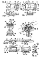
- FIG. 1 is an exploded view of the two intermateable hybrid connectors 10A, 10B also shown intermated in FIGS. 2, 4 and 5.
- the male connector 10A and the female connector 10B are similar, but slightly different in internal assembly, and sometimes are identified generically by the number 10.
- Each connector 10 comprises two connector half shells 12 which, in the embodiment illustrated in the drawing, are identical to one another and fully hermaphroditic as will be described in detail hereinafter with reference to FIGS. 6 through 9.
- the respective connector half shells 12 are joined together to form a housing 13 which engages flanges 14 of one of a pair of intermateable electrical connectors 16, 18.
- Each of the connectors 16, 18 may utilize electrical contacts and intermating designs of generally known constructions. For example, they may utilize the illustrated pin and socket contacts 19, 21 (see FIGS. 3A, 3B, 4A, 4B) or ribbon-type contacts, or they may include coaxial cable contacts. Further they may be of a high density multiple contact design, such as the ribbon-type connectors illustrated in McKee et al. United States Patent No. 4,040,702 and McKee United States Patent No. 4,113,179 and which are sold commercially by TRW Inc. of Elk Grove Village, Illinois under the trademarks CINCH RIBBON and SUPERIBBON, or the pin and socket type connectors illustrated in Arson United States Patent No. 2,790,153 and sold by TRW Inc. under the designation CINCH D-Subminiature connectors. The aforementioned patents are incorporated herein by reference. The electrical connectors 16 and 18 and their contacts are fully engaged with one another when the hybrid connector assemblies 10 are intermated one to another.
- Each of the connectors 10 also includes connector elements for interconnecting optical fibers. These elements include fiber clamps 20, which engage individual fibers 22 and are mounted in movable mounting blocks 24.
- Connector 10A further includes a fiber receptacle 26 which carries a fiber guide 28, while connector 10B includes a retractable fiber guide piston 30.
- An optical fiber 22A is held by a clamp 20 which is mounted in an aperture 32 in a mounting block 24 of connector 10A.
- the fiber 22A extends beyond the clamp 20 and is encompassed by the fiber receptacle 26 which carries the fiber guide 28.
- the opposing connector 10B includes a fiber 22B which is to be connected to the fiber 22A near the center of the fiber guide 28.
- the fiber 22B is held by a clamp 20 which is similarly mounted in an aperture 32 of a mounting block 24.
- the fiber 22B extends beyond the clamp 20 and is encompassed by the spring-loaded retractable piston 30.
- Each of the electrical connectors 16, 18 is of a configuration to accommodate relative reciprocating movement of the receptacle 26 or piston 30, respectively, in adjacent parallel relation to the intermateable electrical contacts.
- the fiber receptacle 26 engages the retractable piston 30 and drives it back towards the associated clamp 20.
- the respective fiber 22B extends out from the piston 30 and into the fiber guide 28.
- the end of the optical fiber 22B is in light transmissive engagement, e.g., abutment contact, with the end of fiber 22A near the center of the fiber guide 28.
- the connectors 16 and 18 provide for the concurrent interconnection between electrical and/or coaxial conductors as well as between optical fibers by the linear mating engagement of the two unified connector assemblies 10.
- the interconnection of the optical fibers 22 is accomplished concurrently and in correlation with but independently of and in isolation from the interconnection of the electrical contacts of the connectors 16, 18 in a single unified connector assembly.
- the electrical connectors 16, 18 can be manufactured in accordance with standard techniques and existing tolerances for electrical connectors, which are generally much less stringent than the techniques and tolerances for optical fiber connectors. However, the more stringent requirements for optical fiber connectors are obtained in the same connector assembly. Moreover all of the interconnections are effected by a single plug-in motion.
- cables coming into the housings such as fiber optic cables C f and/or electrical cables C e
- mechanical strain relief is provided, i.e., strains are transferred from the cables directly to the housing 13 formed by the connector half shells, to minimize strain on the electrical or optical conductors and connections.
- Various clamping collars or inserts 38 may be included for the clamping of cables of different sizes and types.
- the opposing side walls 40 of each shell are formed with channels 42 for reciprocally mounting the blocks 24.
- Fiber cable C fl is composed of a number of concentric sheaths and longitudinally disposed strength members 44 which add tensile strength to the cable and which may comprise plastic or steel filaments.
- the innermost concentric element of fiber cable C f1 comprises an optical fiber 22A which is adapted to convey signals in the normal course of use. Of course, multiple optical fibers may be provided in a single cable.
- Each fiber strain relief clamp 20, shown in more detail in FIGS. 12 through 15, is molded as a single piece of plastic material and is hingedly folded to wrap around an optical fiber 22 normal to the axis of the fiber.
- a clamp 20 clamps, supports and provides strain relief for each individual fiber 22.
- the lower portion of each strain relief clamp 20 comprises a cylindrical post 46 which is inserted into one of a plurality of apertures 32 in a mounting block 24, see FIGS. 10 and 11.
- the post 46 extends normal to the axis of a clamped fiber and includes a beveled end portion 48.
- Each aperture 32 includes a beveled entrance 32A to facilitate entry of the post 46 into one of the respective apertures 32.
- Placement of a clamp 20 into a mounting block 24 is further enhanced by positioning the apertures 32 within grooves 50 formed in the top of mounting block 24.
- Posts 46 frictionally engage the apertures 32 to secure the clamps 20 to the mounting blocks 24.
- Each clamp 20 includes a first clamping portion 52 and a second clamping portion 54 which are interconnected by a thinner integral hinge portion 56.
- the clamping portions 52 and 54 include rounded fiber clamping surfaces 52A and 54A as best seen in FIGS. 12 and 15.
- the apexes of rounded surfaces 52A and 54A engage and clamp an optical fiber.
- the rounded contours present smooth surfaces to a fiber to avoid micro bending and the losses associated with micro bending as optical fibers flex and bend during connector intermating.
- the clamping portions 52 and 54 include cylindrical post portions 46A and 46B respectively which contact one another to form the post 46 when the clamp is folded upon itself about hinge axis 57.
- Clamping portion 54 includes a three-quarter cylindrical projection 58 extending from one side thereof and the clamping portion 52 includes a reversed three-quarter cylindrical projedtion 60 extending from its opposite side.
- Clamp portion 52 is provided with a channel 62 to accommodate a portion of the projection 58 when the clamp is folded as shown in FIG. 12.
- a similar channel 64 in the clamping portion 54 accommodates a portion of the projection 60.
- the projection 58 constitutes a three-quarter cylindrical section, extending from the three o'clock to twelve o'clock positions, while the projection 60 constitutes a three-quarter cylindrical section, extending from the twelve o'clock to nine o'clock positions.
- FIGS. 12 through 15 A review of FIGS. 12 through 15 reveals that clamp 20, when folded, appears the same whether viewed from the front or the back. This "symmetry" facilitates fiber clamping since special orientation of the clamp is unnecessary when folding a clamp about a fiber.
- Clamp 20 is hingedly folded about a fiber 22 so that the fiber is engaged by the rounded surfaces 52A and 54A of the clamping portions 52 and 54 as shown in FIG. 12.
- Post 46 of the clamp then is inserted into one of the apertures 32 in a mounting block 24 to support the clamped fiber in a horizontal position.
- the fiber is supported at both sides of the clamping portions 52 and 54 by cantilevered support surfaces 58A and 60A formed by the projections 58 and 60.
- Support surfaces 58A and 60A are rounded, as best seen in FIG. 14, to provide supporting contact with the fiber at two predetermined points to insure that the fiber protrudes perpendicularly from the clamp.
- Projections 58 and 60 include peripheral grooves 58B and 60B respectively, for spring support purposes as noted further below.
- Hinge 56 includes an elongated aperture 66 which provides for convenient adjustment of the position of a fiber after it has been clamped and mounted in the mounting block 24. Adjustment of the fiber may be necessary if it becomes misaligned from the horizontal after clamping. Adjustment is conveniently accomplished by inserting a pointed object (not shown), such as a pin, into aperture 66 and applying a prying force to the pointed object to spread clamping portions 52 and 54 apart. Fiber 22 can then be repositioned before allowing the clamp to return to its clamping position.
- a pointed object such as a pin
- Resilient hinge 56 also reduces the required tolerances between post 46 and aperture 32, into which it is fitted, and insures a firm yet gentle clamping of the fiber between clamping portions 52 and 54. If a tight fit between a post 46 and an aperture 32 occurs, hinge 56 permits a slight opening motion of the upper portions of clamping portions 52 and 54 to maintain a firm yet gentle clamping force on the fiber. On the other hand, if the tolerances of a post 46 and an aperture 32 result in a loose yet firm fit, the hinge 56 maintains approximately the same firm yet gentle clamping force on the fiber.
- the combination of a mounting block-24 and fiber clamp 20 with a fiber clamped therein serves as a convenient reference for rapidly and accurately measuring and cutting the fibers for interconnection in the connector of the present invention.
- the use of this clamp mounting combination also simplifies the requirements for the fiber cutting tool, the assembly of the connectors and the handling of the fibers.
- Each mounting block 24 includes a leaf spring portion 34 comprising resilient arms 34A and 34B.
- Each mounting block 24 and the leaf spring 34 preferably comprise an integral plastic part.
- the outer ends of the front surface 24A and the outer ends of the arms 34A and 34B frictionally engage the front and rear end shoulders 42A and 42B respectively of the opposed channels 42 which are formed on the inside of side walls 40 of each half shell 12.
- Each mounting block 24 is dimensioned relative to the length of the respective channels 42 to permit the block to retract or move away from its associated electrical connector by compression of the spring 34 against the rearward end shoulders 42B of the channels.
- the front end shoulders 42A serve as forward stops to position the block in the shell.
- a fiber receptacle 26 is fitted over each'fiber 22A.
- An extension 26A of each receptacle then is inserted into an aperture 68 in the male electrical connector 16, and the combination of the mounting block, clamp, fiber, receptacle and electrical connector are inserted into the lower housing half shell.
- the aperture 68 extends through an insulator body 16A of the connector 16, parallel to the contacts of the electrical connector, and is of a size to accommodate free reciprocating movement of the receptacle extension 26A therein.
- Fiber receptacle 26 includes fiber guide 28 in the extension 26A which slidably engages the aperture 68 of the connector 16.
- the fiber guide 28 can be frictionally inserted into extension 26A or may be imbedded therein during the formation of the receptacle.
- An aperture 26B formed in receptacle extension 26A, through which the end of optical fiber 22A is threaded to enter fiber guide 28, has an inner tapered entryway 70 to facilitate insertion of the optical fiber into the aperture.
- the fiber receptacle 26 includes an annular shoulder 72 which engages an inner face 74 of the connector 16.
- the receptacle extension 26A, which includes the fiber guide 28, extends beyond the outer face of connector 16 to serve as a male mating pin for the optical fiber.
- FIG. 3 is a cross-section through the left half connector housing of FIG. 2 along the line 3-3.
- Wire shield 76 is engaged in channels 78 formed on the inside of side walls 40 of the hermaphroditic connector half shells 12. As shown in FIG. 3, the thickness of edges 80 of shield 76 are double the depth dimension of channels 78 such that shield 76 is securely held within two half shells 12 when they are mated together to form a connector housing 13.
- Shield 76 provides separation of electrical conductors which go above the shield and optical fibers and optical fiber connecting elements which go beneath the shield.
- the interconnection of electrical conductors and coaxial cables is via pin and socket connections in accordance with well known techniques and will not be further described in the present application. Perspective views of the mating ends of the connectors 10A and 10B are shown in FIGS. 3A and 3B respectively.
- FIGS. 3A and 3B clearly show that the illustrated embodiment interconnects five electrical conductors and two optical fibers.
- optical fiber guide 28 employed in the fiber receptacle 26 of FIGS. 1 and 4 is not per se an inventive feature of the hybrid connector.
- the use of such optical fiber guides is disclosed in U.S. Patent No. 4,225,214, which is incorporated herein by reference.
- Optical fiber guide 28 as is clearly seen in FIG. 18 comprises an assembly of three or more glass rods such as rods 82, 84 and 86 arranged in side-by-side relationship and parallel to each other. Longitudinal peripheral portions of adjacent rods are in contact and fused together so as to form a cusp- shaped interstitial channel or fiber passageway 88 illustrated in sectional view in FIG. 19. It will be noted from FIG. 18 that the end portions of the rods defining opposed entranceways 90 are of smaller diameter than the remaining rod portions. The entranceways 90 are thus of greater cross-sectional area than the inner interstitial passageway 88. Such enlarged openings at opposed ends of the optical fiber guide 28 facilitate threading or entering of an optical fiber end into the passageway.
- FIG. 18 illustrates an optical fiber guide 28 composed of three glass rods 82, 84 and 86
- FIG. 17 illustrates an assembly 92 of four glass rods 94 which forms a passageway having four cusps. Also, the rods 94 thereof are formed about a uniform arc.
- a four rod assembly 92 provides upper and lower cusps as seen in FIG. 17 which facilitates alignment of fiber ends to be connected within the guide.
- a four-rod assembly having a bent profile as in FIG. 18 is the preferred guide for use in the illustrated embodiment.
- the fiber guide 28 may be molded into extension 26A of receptacle 26 if so desired.
- the receptacle may be formed of a moldable plastic such as Nylon, ABS, Styrene, Noryl, or a castable plastic such as an epoxy resin. In the course of such molding, care must be taken to plug opposed guide entranceways 90 with a readily removable material so as to insure that no guide passageway portion is plugged in the course of embedding guide 28 in the receptacle extension.
- the righthand housing half shells 12 receive the female electrical connector 18, and a mounting block 24 is mounted into opposed channels 42 of the lower housing half shell 12.
- Fiber cable C f2 including strength members 96, is clamped in scallops of the righthand connector housing.
- the innermost concentric element of fiber cable C f2 comprises optical fiber 22B which is to be placed in contact with fiber 22A.
- Fiber 22B is clamped by a fiber clamp 20 and the fiber clamp 20 is inserted into an aperture 32 of a mounting block 24 as previously described. After fiber 22B is clamped in the mounting block 24, the fiber is cut to a predetermined length such that it will contact fiber 22A in fiber guide 28 once the connector housings are mated together as shown in FIGS. 2 and 4.
- Piston 30 includes extension 30A which extends into an aperture 100 of an insulator body 18A of the connector 18 as shown in FIGS. 4, 4A and 4B.
- Spring 98 forces piston 30 toward the electrical connector 18 such that an annular shoulder 102 engages inner surface 104 of connector 18 and extension 30A extends to and is approximately flush with outer surface 106 of the insulator body 18A of the connector 18 as shown in FIG. 4A and indicated by the dashed line 108 in FIG. 4.
- Aperture 110 of piston 30, through which the end of optical fiber 22B is threaded, has' inner tapered entryway 112 to facilitate insertion of the optical fiber into the opening. Entranceway 90 to fiber guide 28 provides room in which the fiber may bend in the course of entering the fiber guide.
- FIGS. 4A, 4B and 4 are sectional views of the upper central portion of the connectors 10 of FIG. 4.
- FIG. 4A the initial state of intermating of the connectors is shown.
- the electrical connectors 16, 18 are aligned with one another and the electrical contacts and optical connecting elements are just touching or in initial mating contact with one another.
- a recess 114 in the distal end of piston 30 mates with the conical distal end 116 of fiber receptacle extension 26A which is projecting from the outer face of the electrical connector 16.
- fiber receptacle 26 is telescopically received in the aperture 100 of the connector 18 and forces the spring loaded piston 30 to retract toward the respective clamp 20 which spring 98 also engages.
- optical fiber 22B proceeds into entryway 90 of optical fiber guide 28, see FIG. 18.
- electrical pin contacts 19 of the male connector 16 concurrently engage and are received by electrical socket contacts 21 of the female connector 18.
- FIG. 4B the electrical connectors 16, 18 are almost completely engaged with one another.
- the retractable piston 30 seats upon its associated clamp 20 and the end of fiber 22B contacts the end of fiber 22A near the center of fiber guide 28 in the fiber receptacle extension 26A.
- the optical fiber connection is complete, under the tolerance control of the lengths of the fibers 22A and 22B extending from the clamps 20 and the lengths of the receptacle 26 and piston 30 extending between the clamps.
- Fibers 22A and 22B preferably will have been cut to provide slight excess length as previously described to insure their contact within fiber guide 28.
- the excess fiber as compared to the dimension established by the receptacle 26 and piston 30, forms "drip loops" 122 within the receptacle and the piston, as shown in exaggerated scale in FIGS. 4B and 4.
- the electrical connectors 16, 18 are not fully seated at this stage of interconnection. Accordingly, the integrity of the electrical connection of the contacts for electrical conductors is not yet insured.
- a slight additional closing or interconnecting motion of the connectors to their fully intermated condition is required. This motion is accommodated by the movability of the mounting blocks 24 permitted by the springs 34, relative to the housings 13 and the attached electrical connectors 16, 18, whereby the housings and the electrical connectors may be advanced to their fully intermated positions independently of the optical fiber connection, as shown in FIG. 4.
- the springs 34 preferably are of much greater compressive strength, i.e., much greater modulus of elasticity than the spring 98, whereby the piston 30 normally will seat against the respective clamp 20 to allow completion of the fiber optic connection prior to relative retractive movement of the clamps 20 and blocks 24.
- mounting blocks 24 can be used to urge the mounting blocks toward their associated connectors.
- the slight articulation of mounting blocks 24 is indicated by gaps 124 between the end shoulders 42A of channels 42 and the front surface 24a of mounting blocks 24, which gaps are exaggerated in the drawing for illustration. In this regard, the gaps remaining for full seating of the electrical connectors 16, 18 after completion of. the optic connections also are exaggerated in FIGS. 4A and 4B, for purpose of illustration.
- Fibers 22A and 22B also form drip loops 126 between mounting blocks 24 and the cable clamps at the ends of the housings.
- Each of the connector housings 13 is formed from two half shells 12 to support and retain the components of the respective assembly in their required cooperative relationship to form a unitary hybrid connector. Each housing 13 also provides the means to retain a connector 10 in intermated connection with a cooperative array of electrical contacts and optical fibers, such as in a like connector.
- One embodiment of the hermaphroditic connector half shells 12 is shown in FIGS. 6 through 9.
- the illustrated housing half shell structure allows an identical unitary molded part to be used in place of up to four parts to form intermating connector housings. Two of the housing half shells 12 are snapped together to form one connector housing 13 which can, in turn, be snapped together with-a like housing, see FIG. 2.
- Each half shell 12 includes two split posts 128 positioned diagonally opposite to one another and matching snap sockets 130 also positioned diagonally opposite to one another. Each socket 130 receives a split upper extension 132 of the respective post 128 when two of the housing half shells 12 are interconnected face to face.
- the connector half shells 12 provide a convenient structure for assembly of the various optical fiber and electrical connecting parts. Once the parts are assembled on a lower half shell, an upper half shell is snapped onto the lower half shell to hold the parts in place and form a connector housing 13. As described above, the resulting housing clamps the cables and mounts both the electrical and the optical fiber connecting elements in their cooperative relationships.
- Each connector housing 13 also has two diagonally opposite flexible fingers 134 and snap latches 136 at its mating end. When two connector housings 13 are connected together, the fingers 134 engage the snap latches 136 to securely interconnect the connector housings 13 and the respective components, both electrical and optical.
- Cantilever disconnect arms 138 are positioned within slots 140 of each housing half shell 12 with the ends of arms 138 being positioned adjacent to the snap latches 136. Disconnect arms 138 are positioned to permit flexible fingers 134 to engage snap latches 136 as best shown in FIG. 5. Disconnect arms 138 are sufficiently flexible so that they can be depressed by hand pressure to disengage flexible fingers 134 from snap-latches 136. Accordingly, two connector housings 13 which have been connected together can be released from one another by applying pressure to the four disconnect arms 138, such as by pressure exerted by the thumbs and index fingers of both hands to both housings 13. Should a more permanent interconnection be desired, a wire, screw, nut and bolt or other fastener can be inserted through apertures 142 of flanges 14 of electrical connectors 16 and 18 to accommodate such permanent interconnection.
- a single flexible finger and mating latch/disconnect arm at the mating end of the connector housings.
- Such a simplified, single latch arrangement can be attained by providing two different half shell designs, e.g., one with a finger similar to finger 134 centrally located on its mating end, and one with a latch similar to latch 136 centrally located on its mating end. Two such half shells would be snapped together to form a connector housing in the manner described above.
- any such connector housing containing the male connector elements may be joined with any such connector housing containing the female connector elements.
- the fingers and latches of the connector housings will assure.proper polarization for joining the male and female connectors.
- two identical half shells having such fingers thereon could be joined to one another to form one housing, and two identical half shells having such latches thereon could be joined to one another to form another housing.
- Male connector elements would be placed in one housing and female connector elements would be placed in the other.
- Each such connector housing thereby would be readily identified as male or female and the orientation of the connector elements in the respective housings would not be critical since the housings would not be polarized. However, polarization would be determined by other means or by the user when mating those connector housings.
- the fiber receptacle of the male connector could be spring loaded relative to its fiber clamp similar to the spring loaded mounting of the piston of the female connector.
Landscapes
- Physics & Mathematics (AREA)
- General Physics & Mathematics (AREA)
- Optics & Photonics (AREA)
- Mechanical Coupling Of Light Guides (AREA)
Applications Claiming Priority (8)
| Application Number | Priority Date | Filing Date | Title |
|---|---|---|---|
| US27595081A | 1981-06-22 | 1981-06-22 | |
| US275845 | 1981-06-22 | ||
| US06/275,846 US4448481A (en) | 1981-06-22 | 1981-06-22 | Fiber optic clamp |
| US06/275,845 US4449784A (en) | 1981-06-22 | 1981-06-22 | Hybrid optical/electrical connector |
| US275950 | 1981-06-22 | ||
| US275844 | 1981-06-22 | ||
| US06/275,844 US4445750A (en) | 1981-06-22 | 1981-06-22 | Articulating fiber optic connectors with resilient mounting block |
| US275846 | 1999-03-24 |
Publications (2)
| Publication Number | Publication Date |
|---|---|
| EP0070098A2 true EP0070098A2 (fr) | 1983-01-19 |
| EP0070098A3 EP0070098A3 (fr) | 1984-09-19 |
Family
ID=27501142
Family Applications (1)
| Application Number | Title | Priority Date | Filing Date |
|---|---|---|---|
| EP82303028A Withdrawn EP0070098A3 (fr) | 1981-06-22 | 1982-06-11 | Coupleur hybride pour conducteurs optiques/électriques, coupleur pour fibres optique, crampon pour fibre optique et logement covenable |
Country Status (1)
| Country | Link |
|---|---|
| EP (1) | EP0070098A3 (fr) |
Cited By (6)
| Publication number | Priority date | Publication date | Assignee | Title |
|---|---|---|---|---|
| EP0320214A3 (en) * | 1987-12-08 | 1990-08-16 | Molex Incorporated | Shielded fiber optic connector assembly |
| EP0307518B1 (fr) * | 1984-06-08 | 1993-07-28 | The Whitaker Corporation | Connecteurs à fibre optique à haute précision |
| GB2272537A (en) * | 1992-11-13 | 1994-05-18 | Seiko Giken Kk | Curved groove optical fiber splicer for ribbon-shaped optical fibre cords |
| EP0908970A1 (fr) * | 1997-10-13 | 1999-04-14 | Siemens Aktiengesellschaft | Connecteur hybride pour hyperfréquences |
| US6033262A (en) * | 1996-07-31 | 2000-03-07 | Siemens Aktiengesellschaft | Contact spring |
| WO2012074990A3 (fr) * | 2010-11-30 | 2012-11-08 | Corning Cable Systems Llc | Connecteurs de fibres optiques pouvant être installés sur le terrain et ensembles de câbles associés |
Family Cites Families (6)
| Publication number | Priority date | Publication date | Assignee | Title |
|---|---|---|---|---|
| DE2508488A1 (de) * | 1975-02-27 | 1976-09-02 | Bach & Co | Steckverbinder zur herstellung elektrischer und optischer verbindungen |
| US4140366A (en) * | 1977-04-19 | 1979-02-20 | Bunker Ramo Corporation | Fiber optic connector assembly |
| US4178068A (en) * | 1977-11-14 | 1979-12-11 | Amp Incorporated | Fiber optic cable termination means |
| US4253730A (en) * | 1977-11-17 | 1981-03-03 | Thomas & Betts Corporation | Optical fiber connector |
| US4184742A (en) * | 1978-10-26 | 1980-01-22 | International Telephone And Telegraph Corporation | Hermaphroditic fiber optic connector |
| JPS5567713A (en) * | 1978-11-15 | 1980-05-22 | Nippon Telegr & Teleph Corp <Ntt> | Optical u link connector |
-
1982
- 1982-06-11 EP EP82303028A patent/EP0070098A3/fr not_active Withdrawn
Cited By (8)
| Publication number | Priority date | Publication date | Assignee | Title |
|---|---|---|---|---|
| EP0307518B1 (fr) * | 1984-06-08 | 1993-07-28 | The Whitaker Corporation | Connecteurs à fibre optique à haute précision |
| EP0320214A3 (en) * | 1987-12-08 | 1990-08-16 | Molex Incorporated | Shielded fiber optic connector assembly |
| GB2272537A (en) * | 1992-11-13 | 1994-05-18 | Seiko Giken Kk | Curved groove optical fiber splicer for ribbon-shaped optical fibre cords |
| GB2272537B (en) * | 1992-11-13 | 1996-10-02 | Seiko Giken Kk | Curved groove optical fiber splicer for ribbon-shaped optical fiber cords |
| US6033262A (en) * | 1996-07-31 | 2000-03-07 | Siemens Aktiengesellschaft | Contact spring |
| EP0908970A1 (fr) * | 1997-10-13 | 1999-04-14 | Siemens Aktiengesellschaft | Connecteur hybride pour hyperfréquences |
| WO2012074990A3 (fr) * | 2010-11-30 | 2012-11-08 | Corning Cable Systems Llc | Connecteurs de fibres optiques pouvant être installés sur le terrain et ensembles de câbles associés |
| US10180539B2 (en) | 2010-11-30 | 2019-01-15 | Corning Optical Communications LLC | Field-installable fiber optic connectors and related cable assemblies |
Also Published As
| Publication number | Publication date |
|---|---|
| EP0070098A3 (fr) | 1984-09-19 |
Similar Documents
| Publication | Publication Date | Title |
|---|---|---|
| US4449784A (en) | Hybrid optical/electrical connector | |
| US4445750A (en) | Articulating fiber optic connectors with resilient mounting block | |
| EP0762558B1 (fr) | Dispositif de verrouillage anti-accrochage d'un connecteur | |
| CA2179833C (fr) | Connecteur double anti-accroc | |
| JP2558346B2 (ja) | コネクタ組立体 | |
| US4201444A (en) | Single optical fiber connector | |
| US5386487A (en) | Apparatus for maintaining plug assemblies of optical fiber connectors in a side by side relation with float therebetween | |
| US5896479A (en) | Massive parallel optical interconnect system | |
| CN104335090B (zh) | 用于光纤连接器的高密度多光纤 | |
| US12411298B2 (en) | Optoelectronic connections to printed circuit boards | |
| US20100266245A1 (en) | Fiber termination for fiber optic connection system | |
| JPH0432363B2 (fr) | ||
| JPH09329724A (ja) | 固定のフェルールを含む光学コネクタ | |
| CA1094367A (fr) | Connecteurs de guides d'ondes optiques pour cables de guides d'ondes multiples | |
| US20120141070A1 (en) | Connector assembly with improved structure on a bracket for mounting connectors | |
| EP1442327B1 (fr) | Ensemble de broches d'alignement pour connecteurs de fibres optiques | |
| US11635576B2 (en) | Ferrule sub-assembly for a fiber optic connector | |
| GB2113866A (en) | Opical fibre connector having double diameter rods | |
| EP1191639B1 (fr) | Système de positionement de câbles pour un assemblage de connecteurs | |
| US5748818A (en) | Massive parallel optical interconnect system | |
| US4448481A (en) | Fiber optic clamp | |
| EP0070098A2 (fr) | Coupleur hybride pour conducteurs optiques/électriques, coupleur pour fibres optique, crampon pour fibre optique et logement covenable | |
| KR20220145160A (ko) | 플러그 커넥터 | |
| CA1195541A (fr) | Connecteur et son logement pour fibres optiques et ensembles hybrides | |
| JP2623998B2 (ja) | 光コネクタ |
Legal Events
| Date | Code | Title | Description |
|---|---|---|---|
| PUAI | Public reference made under article 153(3) epc to a published international application that has entered the european phase |
Free format text: ORIGINAL CODE: 0009012 |
|
| AK | Designated contracting states |
Designated state(s): DE FR GB IT |
|
| PUAL | Search report despatched |
Free format text: ORIGINAL CODE: 0009013 |
|
| AK | Designated contracting states |
Designated state(s): DE FR GB IT |
|
| STAA | Information on the status of an ep patent application or granted ep patent |
Free format text: STATUS: THE APPLICATION IS DEEMED TO BE WITHDRAWN |
|
| 18D | Application deemed to be withdrawn |
Effective date: 19850520 |
|
| RIN1 | Information on inventor provided before grant (corrected) |
Inventor name: MARGOLIN, MARK Inventor name: BOSOV, EMMA Inventor name: BERG, ALAN Inventor name: GROIS, IGOR |