EP0070108A1 - Verbesserungen an Fühlern für Messgeräte - Google Patents
Verbesserungen an Fühlern für Messgeräte Download PDFInfo
- Publication number
- EP0070108A1 EP0070108A1 EP82303235A EP82303235A EP0070108A1 EP 0070108 A1 EP0070108 A1 EP 0070108A1 EP 82303235 A EP82303235 A EP 82303235A EP 82303235 A EP82303235 A EP 82303235A EP 0070108 A1 EP0070108 A1 EP 0070108A1
- Authority
- EP
- European Patent Office
- Prior art keywords
- stylus member
- transducer
- probe according
- housing
- kinematic location
- Prior art date
- Legal status (The legal status is an assumption and is not a legal conclusion. Google has not performed a legal analysis and makes no representation as to the accuracy of the status listed.)
- Granted
Links
Images

Classifications
-
- G—PHYSICS
- G01—MEASURING; TESTING
- G01B—MEASURING LENGTH, THICKNESS OR SIMILAR LINEAR DIMENSIONS; MEASURING ANGLES; MEASURING AREAS; MEASURING IRREGULARITIES OF SURFACES OR CONTOURS
- G01B7/00—Measuring arrangements characterised by the use of electric or magnetic techniques
- G01B7/004—Measuring arrangements characterised by the use of electric or magnetic techniques for measuring coordinates of points
- G01B7/008—Measuring arrangements characterised by the use of electric or magnetic techniques for measuring coordinates of points using coordinate measuring machines
- G01B7/012—Contact-making feeler heads therefor
Definitions
- This invention relates to a probe for use in measuring apparatus, more especially three dimensional coordinate measuring apparatus.
- the probe determines the point in space at which contact is established between a stylus and a test surface.
- One alternative use of such a probe is in a setting gauge.
- Such probes are known, for example from U.K. Specifications No. 1,445,977 and No. 1,447,613.
- a stylus member is kinematically located relative to a support to establish a circuit path through a pair of contacts, one on the support and one on the stylus member.
- three such pairs of contacts define the kinematic location.
- detection is effected through an inductive coupling which couples an oscillator powered driving circuit with a driven circuit completed by the contacts of the kinematic location.
- the reaction on the driving circuit through the inductive coupling is measured to determine opening of the contacts.
- a probe comprising a support, a stylus member having a sensing tip, means on the support defining a kinematic location for the stylus member, means urging the stylus member against said kinematic location to effect relocation thereof after displacement due to contact of the tip with a test surface, a capacitative transducer having one part carried by the support and one part carried by the stylus member, and circuit means connected to said transducer to detect a change in capacitance due to displacement of the stylus member relative to the support.
- detection and relocation of the stylus member can be more accurate due to their relative independence.
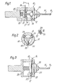
- the probe shown in Figures 1 and 2 comprises a housing 10 which may be mounted, for example, in coordinate measuring apparatus.
- the housing 10 has a kinematic location 12 for a stylus member 14 having a spherical sensing tip 16.
- the kinematic location 12 is most clearly shown in Figure 2, and comprises three seatings 18 at 120 degrees angular spacings.
- Three transverse arms 20 consisting of ' rollers are provided on the stylus member 14 each engaging a pair of balls 24 fixed within the recesses 26 in housing 10. This type of kinematic location provides lateral constraint in one direction.
- the stylus member 14 When in use the tip 16 contacts the test surface (not shown), the stylus member 14 is displaced, at least in part longitudinally, and the kinematic location is broken at one or more-of the seatings 18. Relocation of the stylus member 14 against its kinematic seatings 18 is achieved by means of a biasinq spring 28 acting between the housing 10 and the stylus member. Displacement of the stylus member 14 takes place against the biasing action of this spring.
- a capacitative transducer For detecting contact of the tip 16 with the test surface, a capacitative transducer is provided.
- One capacitor plate 30 is carried by the stylus member 14 and the other capacitor plate 32 is carried by the housing 10.
- the plate 30 is mounted directly to the inner end of the stylus member 14, and serves as an abutment for the spring 28.
- the plate 32 is mounted to the housing through the intermediary of an electrically insulating ring 34.
- the housing 10 is a housing sealed to prevent ingress of dirt and moisture, to which end a flexible seal 38 is provided between the housing and the projecting end portion of the stylus member 14 carrying the sensing tip 16.
- the housing 10 may be filled with oil to increase the sensitivity of the transducer and to ensure that it operates in a.stable environment.
- oil can also serve to lubricate the kinematic location 12 and to dampen mechanical vibrations, thus preventing false readings.
- capacitor plate 30 carries the transverse arms 20 carrying the rollers and balls for the kinematic location 12.
- the capacitor plate 30 seats against three equi-angularly spaced balls 40 secured in V-recesses 42 in the bottom of the housing 10.
- the stylus member 14 includes a thick inner end portion 15 acted upon through a ball 29 by the biasing spring 28.
- a flexible diaphragm 44 is mounted between the housing 10 and the inner end portion 15 of the stylus member 14. This type of mechanical relocation system comprising diaphragm and three point contact allows three degrees of movement for the stylus member 14 whilst maintaining radial constraint.
- Figure 5 shows, in simplified form, an electronic drive circuit for the probe with capacitative transducer, as already exemplified with reference to Figures 1 to 4.
- the capacitative transducer 50 (formed by capacitor plates 30, 32) is incorporated in a bridge circuit 52 fed by an alternating current signal from an oscillator 54.
- the oscillator signal is amplitude modulated (or the amplitude of modulation is altered).
- the output of the bridge circuit '52 is amplified at 55 and fed to a comparator 56 at which the level of the modulation signal is detected with respect to a predetermined d.c. voltage.
- the comparator 56 When an alteration in the amplitude of the modulated signal occurs due to movement of the stylus member responsive to contact of the sensing tip with the test surface, the comparator 56 is switched at a rate governed by the operating frequency of the oscillator 54.
- a logic circuit 58 detects the train of pulses output from the comparator 56 and produces a d . c . level output signal 60, indicating that the tip has made contact with the test surface.
Landscapes
- Physics & Mathematics (AREA)
- General Physics & Mathematics (AREA)
- Measurement Of Length, Angles, Or The Like Using Electric Or Magnetic Means (AREA)
- A Measuring Device Byusing Mechanical Method (AREA)
Applications Claiming Priority (2)
| Application Number | Priority Date | Filing Date | Title |
|---|---|---|---|
| GB8119369 | 1981-06-23 | ||
| GB08119369A GB2101325B (en) | 1981-06-23 | 1981-06-23 | Contact sensitive probes using capacitative sensors |
Publications (2)
| Publication Number | Publication Date |
|---|---|
| EP0070108A1 true EP0070108A1 (de) | 1983-01-19 |
| EP0070108B1 EP0070108B1 (de) | 1987-09-09 |
Family
ID=10522758
Family Applications (1)
| Application Number | Title | Priority Date | Filing Date |
|---|---|---|---|
| EP82303235A Expired EP0070108B1 (de) | 1981-06-23 | 1982-06-22 | Verbesserungen an Fühlern für Messgeräte |
Country Status (5)
| Country | Link |
|---|---|
| US (1) | US4498043A (de) |
| EP (1) | EP0070108B1 (de) |
| JP (1) | JPS585601A (de) |
| DE (1) | DE3277233D1 (de) |
| GB (1) | GB2101325B (de) |
Cited By (6)
| Publication number | Priority date | Publication date | Assignee | Title |
|---|---|---|---|---|
| EP0116807A1 (de) * | 1983-02-21 | 1984-08-29 | GAME INGENIERIE Société Anonyme | Ein entlang wenigstens zwei orthogonalen Axen verschiebbarer Schlitten mit einem Kopf zum Messen, Kontrollieren, Bearbeiten, Kopieren oder ähnlichem |
| GB2141364A (en) * | 1983-06-14 | 1984-12-19 | Gte Valeron Corp | Touch probe |
| EP0159781A1 (de) * | 1984-03-27 | 1985-10-30 | EMI Limited | Sensor-Vorrichtung |
| US5115186A (en) * | 1989-04-29 | 1992-05-19 | Alfred Teves Gmbh | Travel sensor for determining the position of a member such as a brake pedal |
| EP2889573A1 (de) * | 2013-12-24 | 2015-07-01 | Tesa Sa | Orientbarer motorisierter Messkopf |
| WO2025202616A1 (en) * | 2024-03-28 | 2025-10-02 | Taylor Hobson Limited | Robust kinematic mount and metrological apparatus and method |
Families Citing this family (20)
| Publication number | Priority date | Publication date | Assignee | Title |
|---|---|---|---|---|
| US4734549A (en) * | 1985-11-25 | 1988-03-29 | Rin Ei Seiki Kabushiki Kaisha | Touch sensor |
| US5517124A (en) * | 1989-07-26 | 1996-05-14 | Extrude Hone Corporation | Stylus probe for measuring workpiece surface characteristics |
| US5505005A (en) * | 1990-02-23 | 1996-04-09 | Renishaw Plc | Touch probe |
| US5339535A (en) * | 1990-02-23 | 1994-08-23 | Renishaw Metrology Limited | Touch probe |
| US5189377A (en) * | 1990-09-04 | 1993-02-23 | Extrude Hone Corporation | Method and apparatus for co-ordinate measuring using a capacitance probe |
| GB9021447D0 (en) * | 1990-10-03 | 1990-11-14 | Renishaw Plc | Capacitance probes |
| US5144251A (en) * | 1991-04-02 | 1992-09-01 | The United States Of America As Represented By The United States Department Of Energy | Three-axis particle impact probe |
| JP2577836B2 (ja) * | 1991-07-24 | 1997-02-05 | 三菱電機株式会社 | 発振器監視装置 |
| US5438275A (en) * | 1994-01-03 | 1995-08-01 | International Business Machines Corporation | Digitizing stylus having capacitive pressure and contact sensing capabilities |
| US6150832A (en) * | 1998-03-27 | 2000-11-21 | Solid State Measurements, Inc. | Noncontact capacitance measuring device |
| DE10122200A1 (de) * | 2001-05-08 | 2002-11-14 | Zeiss Carl | Tastkopf für ein Koordinatenmeßgerät. Koordinatenmeßgerät, Kalibrierkörper für ein Koordinatenmeßgerät und Verfahren zum Kalibrieren eines Koordinatenmeßgerätes |
| US20040068881A1 (en) * | 2002-10-15 | 2004-04-15 | Optical Gaging Products, Inc. | Viscous coupled micro interposer |
| ITMO20050085A1 (it) * | 2005-04-08 | 2006-10-09 | M D Micro Detectors S P A | Procedimento di misurazione della variazione di lunghezza di una molla e molla con relativo sensore. |
| US7798011B2 (en) * | 2006-02-08 | 2010-09-21 | Hysitron, Inc. | Actuatable capacitive transducer for quantitative nanoindentation combined with transmission electron microscopy |
| US8717043B2 (en) | 2011-07-27 | 2014-05-06 | International Business Machines Corporation | Determining thermal interface material (TIM) thickness change |
| CN104669063A (zh) * | 2015-02-10 | 2015-06-03 | 成都绿迪科技有限公司 | 一种定位检测装置 |
| JP6017096B1 (ja) * | 2015-10-30 | 2016-10-26 | 三菱電機株式会社 | ワイヤ放電加工機、ワイヤ放電加工機の制御装置の制御方法及び位置決め方法 |
| CN105698661A (zh) * | 2016-03-07 | 2016-06-22 | 安徽电气工程职业技术学院 | 微纳米三坐标测量机接触式扫描探头 |
| CN107869977B (zh) * | 2017-11-23 | 2019-10-22 | 深圳力合精密装备科技有限公司 | 一种坐标测量机测针夹持与调整机构 |
| TWI706297B (zh) * | 2019-02-27 | 2020-10-01 | 群光電子股份有限公司 | 觸控筆 |
Citations (4)
| Publication number | Priority date | Publication date | Assignee | Title |
|---|---|---|---|---|
| DE2718438A1 (de) * | 1977-04-26 | 1978-12-14 | Heinrich Prof Dr Ing Frohne | Taster zur messung raeumlicher koordinaten |
| GB2025073A (en) * | 1978-07-07 | 1980-01-16 | Rolls Royce | Apparatus for Monitoring the State of an Electrical Circuit |
| US4187614A (en) * | 1978-08-04 | 1980-02-12 | Mitsubishi Jukogyo Kabushiki Kaisha | Tracer head |
| DE2905172A1 (de) * | 1979-02-10 | 1980-08-21 | Georg Prof Dipl Ing Seewang | Taster fuer koordinaten-messmaschinen |
Family Cites Families (15)
| Publication number | Priority date | Publication date | Assignee | Title |
|---|---|---|---|---|
| US2510822A (en) * | 1945-05-15 | 1950-06-06 | Jacot Georges | Apparatus for electrically measuring thicknesses |
| US3249833A (en) * | 1964-11-16 | 1966-05-03 | Robert E Vosteen | Capacitor transducer |
| US3696908A (en) * | 1970-11-09 | 1972-10-10 | Sperry Rand Corp | Capacitive key |
| GB1445977A (en) * | 1972-09-21 | 1976-08-11 | Rolls Royce | Probes |
| RO60105A2 (de) * | 1973-07-23 | 1976-08-15 | ||
| JPS50151170A (de) * | 1974-05-27 | 1975-12-04 | ||
| US3948359A (en) * | 1975-04-14 | 1976-04-06 | General Motors Corporation | Vehicle hydraulic shock absorber and indicating system |
| GB1593050A (en) * | 1976-09-30 | 1981-07-15 | Renishaw Electrical Ltd | Contact sensing probe |
| DE2711346C2 (de) * | 1977-03-16 | 1979-03-15 | Truetzschler Gmbh & Co Kg, 4050 Moenchengladbach | Elektronischer Druckschalter |
| US4096758A (en) * | 1977-05-24 | 1978-06-27 | Moore Products Co. | Pressure to electric transducer |
| JPS55104704A (en) * | 1979-02-05 | 1980-08-11 | Hiromi Ogasawara | Detection probe for three dimensional motion |
| US4288836A (en) * | 1979-05-29 | 1981-09-08 | Xerox Corporation | Capacitance controlled keyswitch |
| DE2931489C2 (de) * | 1979-08-03 | 1987-07-09 | Jungheinrich Unternehmensverwaltung Kg, 2000 Hamburg | Steuerhebelschalter |
| US4294321A (en) * | 1980-02-27 | 1981-10-13 | Rca Corporation | Position sensing and display means |
| US4374383A (en) * | 1980-12-22 | 1983-02-15 | International Business Machines Corporation | Capacitive transducer for sensing a home position |
-
1981
- 1981-06-23 GB GB08119369A patent/GB2101325B/en not_active Expired
-
1982
- 1982-06-22 EP EP82303235A patent/EP0070108B1/de not_active Expired
- 1982-06-22 DE DE8282303235T patent/DE3277233D1/de not_active Expired
- 1982-06-23 US US06/391,350 patent/US4498043A/en not_active Expired - Fee Related
- 1982-06-23 JP JP57108253A patent/JPS585601A/ja active Pending
Patent Citations (4)
| Publication number | Priority date | Publication date | Assignee | Title |
|---|---|---|---|---|
| DE2718438A1 (de) * | 1977-04-26 | 1978-12-14 | Heinrich Prof Dr Ing Frohne | Taster zur messung raeumlicher koordinaten |
| GB2025073A (en) * | 1978-07-07 | 1980-01-16 | Rolls Royce | Apparatus for Monitoring the State of an Electrical Circuit |
| US4187614A (en) * | 1978-08-04 | 1980-02-12 | Mitsubishi Jukogyo Kabushiki Kaisha | Tracer head |
| DE2905172A1 (de) * | 1979-02-10 | 1980-08-21 | Georg Prof Dipl Ing Seewang | Taster fuer koordinaten-messmaschinen |
Cited By (8)
| Publication number | Priority date | Publication date | Assignee | Title |
|---|---|---|---|---|
| EP0116807A1 (de) * | 1983-02-21 | 1984-08-29 | GAME INGENIERIE Société Anonyme | Ein entlang wenigstens zwei orthogonalen Axen verschiebbarer Schlitten mit einem Kopf zum Messen, Kontrollieren, Bearbeiten, Kopieren oder ähnlichem |
| GB2141364A (en) * | 1983-06-14 | 1984-12-19 | Gte Valeron Corp | Touch probe |
| EP0159781A1 (de) * | 1984-03-27 | 1985-10-30 | EMI Limited | Sensor-Vorrichtung |
| US5115186A (en) * | 1989-04-29 | 1992-05-19 | Alfred Teves Gmbh | Travel sensor for determining the position of a member such as a brake pedal |
| EP2889573A1 (de) * | 2013-12-24 | 2015-07-01 | Tesa Sa | Orientbarer motorisierter Messkopf |
| US9494403B2 (en) | 2013-12-24 | 2016-11-15 | Tesa Sa | Motorized inclinable measuring head |
| WO2025202616A1 (en) * | 2024-03-28 | 2025-10-02 | Taylor Hobson Limited | Robust kinematic mount and metrological apparatus and method |
| GB2639958A (en) * | 2024-03-28 | 2025-10-08 | Taylor Hobson Ltd | Robust kinematic mount and metrological apparatus and method |
Also Published As
| Publication number | Publication date |
|---|---|
| GB2101325B (en) | 1984-10-17 |
| GB2101325A (en) | 1983-01-12 |
| JPS585601A (ja) | 1983-01-13 |
| US4498043A (en) | 1985-02-05 |
| DE3277233D1 (en) | 1987-10-15 |
| EP0070108B1 (de) | 1987-09-09 |
Similar Documents
| Publication | Publication Date | Title |
|---|---|---|
| US4498043A (en) | Probes for measuring apparatus | |
| EP0605140B1 (de) | Tastsonde und Signalverarbeitungsschaltung dafür | |
| KR910003200B1 (ko) | 중량검출장치 | |
| GB1531209A (en) | Sensing probe | |
| JP2539824B2 (ja) | 測定装置 | |
| JPH0792373B2 (ja) | タッチ信号プローブ | |
| JPH0648166B2 (ja) | 検知装置 | |
| JPS59174710A (ja) | 測定装置の探触子 | |
| US4325259A (en) | Vibration amplitude measuring device | |
| US3978715A (en) | Low frequency, high sensitivity electromechanical transducer | |
| KR940000817Y1 (ko) | 와유량계 | |
| CN108759651A (zh) | 磁力型间隙测量系统及间隙测量系统的磁体安装结构 | |
| JPS60249002A (ja) | 移動距離センサ− | |
| CN219161161U (zh) | 一种接触式测针 | |
| JPH06106240A (ja) | ロールギャップ検出装置およびロール端部形状 | |
| SU987531A1 (ru) | Молекул рно-электронный угловой акселерометр | |
| JPH074488Y2 (ja) | 接触検出装置 | |
| SU1749697A1 (ru) | Устройство контрол пр молинейности образующей цилиндрической детали | |
| KR19980042511U (ko) | 비접촉식 정전용량형 트리거 프로브 | |
| SU1241059A1 (ru) | Датчик перемещений | |
| US3449949A (en) | Force gauge | |
| SU1651097A1 (ru) | Гидромеханическое устройство дл измерени параметров щели | |
| JPH0743603Y2 (ja) | 接触検出装置 | |
| SU678287A1 (ru) | Наклономер | |
| SU587367A1 (ru) | Устройство дл измерени нормальных напр жений к ротационному реогониометру вейссенберга |
Legal Events
| Date | Code | Title | Description |
|---|---|---|---|
| PUAI | Public reference made under article 153(3) epc to a published international application that has entered the european phase |
Free format text: ORIGINAL CODE: 0009012 |
|
| AK | Designated contracting states |
Designated state(s): CH DE FR IT LI |
|
| 17P | Request for examination filed |
Effective date: 19830112 |
|
| RAP1 | Party data changed (applicant data changed or rights of an application transferred) |
Owner name: THE RANK ORGANISATION PLC |
|
| RAP1 | Party data changed (applicant data changed or rights of an application transferred) |
Owner name: THE RANK ORGANISATION PLC |
|
| RAP1 | Party data changed (applicant data changed or rights of an application transferred) |
Owner name: RANK TAYLOR HOBSON LIMITED |
|
| GRAA | (expected) grant |
Free format text: ORIGINAL CODE: 0009210 |
|
| AK | Designated contracting states |
Kind code of ref document: B1 Designated state(s): CH DE FR IT LI |
|
| PG25 | Lapsed in a contracting state [announced via postgrant information from national office to epo] |
Ref country code: FR Free format text: THE PATENT HAS BEEN ANNULLED BY A DECISION OF A NATIONAL AUTHORITY Effective date: 19870909 |
|
| ITF | It: translation for a ep patent filed | ||
| REF | Corresponds to: |
Ref document number: 3277233 Country of ref document: DE Date of ref document: 19871015 |
|
| EN | Fr: translation not filed | ||
| PLBE | No opposition filed within time limit |
Free format text: ORIGINAL CODE: 0009261 |
|
| STAA | Information on the status of an ep patent application or granted ep patent |
Free format text: STATUS: NO OPPOSITION FILED WITHIN TIME LIMIT |
|
| 26N | No opposition filed | ||
| PGFP | Annual fee paid to national office [announced via postgrant information from national office to epo] |
Ref country code: CH Payment date: 19890616 Year of fee payment: 8 |
|
| PGFP | Annual fee paid to national office [announced via postgrant information from national office to epo] |
Ref country code: DE Payment date: 19890829 Year of fee payment: 8 |
|
| ITTA | It: last paid annual fee | ||
| PG25 | Lapsed in a contracting state [announced via postgrant information from national office to epo] |
Ref country code: LI Effective date: 19900630 Ref country code: CH Effective date: 19900630 |
|
| REG | Reference to a national code |
Ref country code: CH Ref legal event code: PL |
|
| PG25 | Lapsed in a contracting state [announced via postgrant information from national office to epo] |
Ref country code: DE Effective date: 19910301 |